Microscopy Research
Vol.03 No.02(2015), Article ID:55924,6 pages
10.4236/mr.2015.32004
Evaluation of the Marginal Adaptation in Metal Crowns Using CAD/CAM and Manual Wax Patterns
Alan Sepulveda-Rodríguez1, Felipe Guerrero-Martínez2, César Gaitan-Fonseca1, Takashi Komabayashi3, Enrique Reyes-Vela1, David Masuoka1
1Department of Stomatology, Universidad Autónoma de Aguascalientes, Aguascalientes, Mexico
2Faculty of Dentistry, Universidad Autónoma de San Luis Potosí, San Luis Potosí, Mexico
3Department of Endodontics, West Virginia University, Charleston, USA
Email: david.masuoka@edu.uaa.mx, david.masuoka@gmail.com
Copyright © 2015 by authors and Scientific Research Publishing Inc.
This work is licensed under the Creative Commons Attribution International License (CC BY).
http://creativecommons.org/licenses/by/4.0/


Received 9 April 2015; accepted 23 April 2015; published 24 April 2015
ABSTRACT
The aim of this study is to evaluate the maximum and minimum distances between the model and the cast crown of three techniques using Scanning Electron Microscopy (SEM). Three technique groups were used for this study: group A (control), traditional manual wax patterns; group B, dipping wax patterns; group C, resin patterns made with CAD/CAM. For each group, 10 samples were made using the same model, and then metal cast. Marginal accuracies of the samples were evaluated by performing gap measurements using SEM with a magnification of 1200× (minimum distance). The data were statistically analyzed using the one-way analysis of variance (ANOVA) at the 0.05 significance level. The average (standard deviation) of the minimum distance [µm] was 22.5 (12.1), 9.9 (4.3), and 14.7 (6.6), in groups A, B, and C, respectively. The average standard deviation of gap area [µm2] was 21667.2 (3476.4), 9906.4 (1512.1), and 16048.8 (8123). In the minimum distance comparison, groups A and B (p = 0.006) showed statistically significant results. In the gap area comparison, there was no statistical significance among groups A, B, and C (p = 0.174). The marginal adaptations of all three techniques were within a reported clinically acceptable range of margin.
Keywords:
Marginal Adaptation, CAD/CAM, Metal Caps, Wax Pattern

1. Introduction
Clinical dentistry has used different types of prostheses for the rehabilitation or replacement of dental organs. Proper sealing and marginal fit of prosthesis provide successful long-term treatment, avoiding complications such as retention of plaque, periodontal injury or recurrent caries [1] -[3] . The marginal seal of a metal cast restoration is thus clinical interest.
It is known that there are two wax pattern fabrication methods widely used. One is manual waxing, and the other is dipping waxing. Manual waxing is a conventional wax-adding technique by heating and melting the wax. Dipping waxing uses an immersion technique with a wax dipping unit at a high temperature. These techniques are also called lost wax techniques. Becker et al. evaluated the marginal seal of crowns made from precious metals using manual waxing technique and concluded that precious metals showed favorable clinical results, thus preventing irritation to the periodontium, bacteria accumulation, and infiltration of the thermal conductivity to the dental organ [4] . Similarly, Christensen et al. evaluated the marginal seal of restorations with noble metals and concluded that an interface of 39 μm was clinically acceptable [5] . Foster et al. studied the most common cause of failure in the placement of crowns, finding that an interface of more than 120 μm caused periodontal complications [6] . In clinic, clinically acceptable level marginal fit is thus important. Manual waxing and dipping waxing techniques require technicians to perform detailed craftsmanship. Accordingly, while manual waxing and dipping waxing techniques are used most frequently, several techniques for the preparation of fixed prostheses have developed in order to facilitate greater productivity and better quality.
Currently, the Computer-Aided Design/Computer-Aided Manufacturing (CAD/CAM) system can create polymer patterns for metal casting and thus potentially eliminate the use of traditional wax patterns that inevitably become deformed and require skilled technicians. In theory, this CAD/CAM system allows an adequate marginal seal, providing better clinical success in the long term. This method can also reduce the time it takes to produce a new restoration. However, the quantitative reports of marginal adaptation using this method are limited [7] .
The aim of this study is to evaluate the differences among three techniques of pattern fabrication, namely, manual waxing, dipping wax, and CAD/CAM, by using Scanning Electron Microscopy (SEM).
2. Materials and Methods
2.1. Master Die
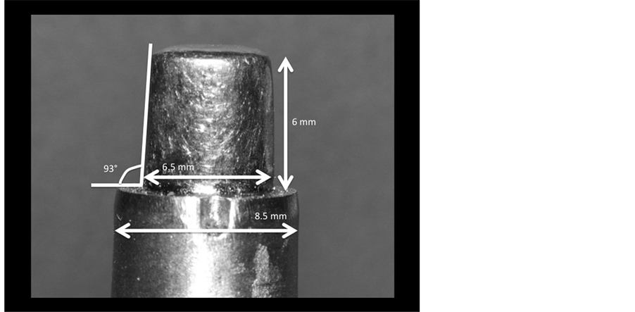
A 3 cm by 2 cm, cylindrical mold was made with all-season wax. Self-curing acrylic Jet Set-4 (Lang Dental Manufacturing Wheeling, IL, USA) was poured into the mold for polymerization. Subsequently, the hub was formed with the aim of obtaining prosthetic configuration parallel walls forming chamfer angle of 3˚, with a 2 mm wide shoulder, a base diameter of 8.5 mm, and a stump diameter of 6.5 mm. On the prosthetic shoulder, a notch 1.4 mm wide and 1.5 mm deep was formed with a high speed cylindrical bur (model # 838-ISO139 014- 314 FG Ø Standard-blue Banda SS White, Lakewood, NJ, USA). Once the acrylic pattern was prepared, it was casted by nickel-chromium metal alloy (Verabond, Albadent, Cordelia CA, USA). This material was used for this purpose basically because it has a proper wear resistance and good resistance to thermal expansion and contraction. The excesses and impurities were removed and polished finishing on the stump area in a master die (Figure 1(a): master die).
Once obtained the master die was used for the wax patterns and acrylate polymer (for CAD/CAM) system. For waxing techniques (groups A and B) two layers of varnish spacer (VITA In-Ceram, VITA Zahnfabrik, BadSäckingen, Germany) was applied on the stump without touching the shoulder. A layer of soft paraffin (lubricant Duralay, Reliance Dental, IL, USA) was applied around the wrist as a separator between the spacer and the molten wax.
2.2. Manufacture of Wax Patterns
The samples were divided into three groups: group A: manual waxing; group B: dipping waxing; group C: CAD/CAM. Ten samples were made in each group.
In group A (manual waxing), wax patterns were fabricated with modeling wax (StarWax, Dentaurum, Ispringen, Germany) using a conventional wax-adding technique with instruments PKT #1, #2 and #4 by heating, melting and detailing the wax with a Bunsen burner using LPG. Two coats of spacer (25 μm) (VITA In-Ceram, VITA Zahnfabrik, BadSäckingen, Germany) were applied on the stump of master die without touching the shoulder. Blue color molten wax is placed on the shoulder, and green color wax was used to form the rest of the
 (a)
(a)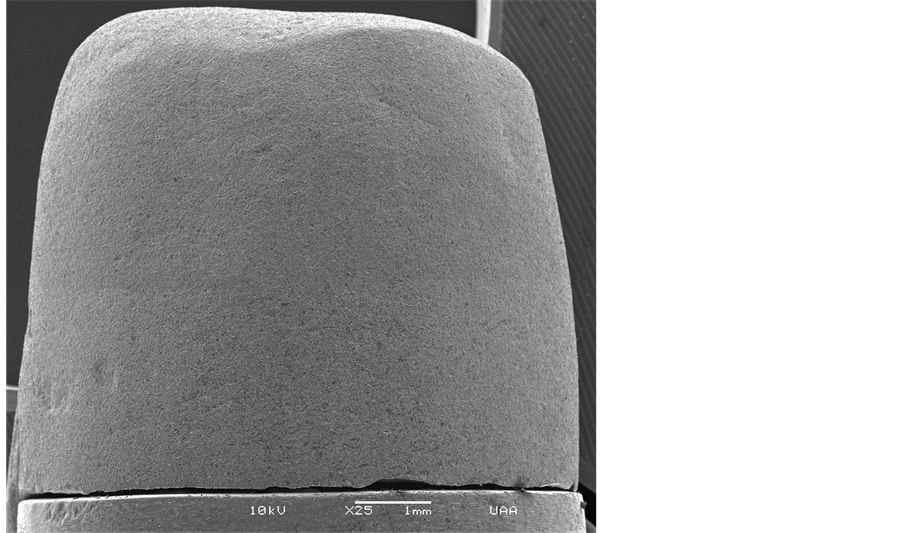 (b)
(b)
Figure 1. (a) Master die; (b) Master die with the casting.
cap. The wax patterns copings were retired with the sticky wax to avoid pressure that can create deformation. The wax patterns were stored in a plastic cup with water at room temperature.
In group B (dipping waxing), wax patterns were fabricated with modeling wax (Wax Dipping, Patterson Brand, IL, USA) using an immersion technique with a wax dipping unit (Hotty LED, Renfert, Hilzingen, Germany) at a temperature of 90˚C. The wax patterns coping were detailed with instrument PKT #4. Two coats of spacer (25 μm) (VITA In-Ceram, VITA Zahnfabrik, BadSäckingen, Germany) were applied on the stump of master die without touching the shoulder. The finished wax patterns were removed from the master die with sticky wax to prevent deformation under pressure and stored in a plastic container with water at room temperature.
In group C (CAD/CAM), the master die was coated with titanium oxide powder (CEREC Powder, VITA Zahnfabrik, BadSäckingen, Germany) and then scanned in a CAD (INEOS Blue, Sirona Dental Systems, Bensheim, Germany). The data were captured and the margin of the prosthetic stump preparation was located and established. The path of placement of the cap was determined and selected to draw up an infrastructure for fixed prosthesis metal-ceramic crown (cap). The acrylate polymer blocks (VITA CAD-Waxx, VITA Zahnfabrik, BadSäckingen, Germany) were processed with the CAM (inLab MC XL, Sirona Dental Systems, Bensheim, Germany). Once the milling process was finished, impurities were removed and cleaned with carbide burs at low speed and air.
2.3. Lost Wax Metal Casting Technique
A small sprues was placed on the top of each pattern and make it stay with the inside facing up, and the other end of sprue joined the casting ring base cap. In each base cap were placed ten patterns. The casting rings were positioned over the casting ring to hold the plaster, which flows around the casting. The phosphate coating plaster (StarVest, Emdin, NJ, USA), the plaster handling was carried out according to the manufacturer’s instructions, 100 grams of powder per 24 ml of liquid. The powder is attached to the liquid, first mixed by hand and then under a vacuum mixer (Speed Dual Combination Unit, Whip Mix, KY, USA) at low speed (425 rpm) for sixty seconds. After the mixture was made, it was rest for thirty seconds with vacuum conditions, after this time, the casting rings were taken to the vibrator to shed the lining starting with a sharp instrument filling all the patterns in the inside parts and then the rest of the casting rings were filled completely. The casting rings were left at room temperature for thirty minutes while the plaster finish set.
Once theplaster has set, the casting ring capwas removed. This leaved the sprueprotruding from the hardened plaster. The casting ringswerethen placed in an oven to a temperature of about 760˚C - 800˚C for 45 minutes to the patterns made of wax and for 70 minutes for acrylate polymer patterns. As the wax and the polymer melted, they leaved a space in the plaster in the shape of the original patterns.
The casting rings were placed one by one in the centrifuge, before casting the metal they were heated with the torch. For the metal casting seven grams of nickel-chrome alloy (Verabond, AalbaDent, CA, USA) were used for each cast ring because this material is used in the confection of the conventional metal-ceramic crowns. Acetylene/oxygen torch was used to melt metal at 1,250˚C. At the end the casted molds were cooled for one hour in a room temperature.
Casted copings were recovered and cleaned, the sprues were removed with a carbide bur and diamond disks using a low speed micromotor to 16,000 revolutions per minute (K.1070 High Speed Rotary Micromotor, Foredom, CT, USA). The copings were sandblasted to fifty pounds of pressure (25 - 70 μm/70 - 250 μm Classic Basic, Renfert, Hilzingen, Germany) with sand (110 μm and 125 μm COBRA, Renfert, Hilzingen, Germany).
Having perfectly clean samples, we proceeded to place the samples on the master die to check if there were some considerable problems (holes or lack of metal). A total of 30 metal copings (10 each group) were castes and organized by marking them with the letter of the group and the number of the sample.
2.4. SEM Analysis Patterns
The method of measuring the interface areas using the SEM followed the specifications of several studies [8] -[12] . Marginal accuracies of the samples were evaluated by performing gap measurements using the Scanning Electron Microscope (JSM-5900LV, JEOL, Japan). The casted sample were individually set to the master die through conductive aluminum tape (Model #77800, Electron Microscopy Sciences, Hatfield, PA, USA) by placing two strips on the outside, one on each side, in order to be placed within the SEM (Figure 1(b): master die with the casting). The samples were analyzed by SEM by locating the interface between the shoulder of the master die prosthetic preparation and the lower edge of the metal coping. On the SEM images, the minimum distance and the gap area were taken at the 1200× magnification for lower micrometer range values (Figure 2: a sample view of the marginal adaptation). Three points were randomly chosen for measurement in each SEM image and the distance was measured in micrometer.
2.5. Statistical Analysis
For each of the three technique groups, these measurements were taken from ten different samples using SEM images. The minimum distances and the gap areas were calculated by using three random, unbiased points for each measurement from the SEM image, and then averaged (total n = 30 for each parameter). The standard deviation (SD) and the coefficient of variation (CV) were calculated. The data were then analyzed by a one-way ANOVA using a software (JMP, SAS, NC, USA).
3. Results
Abbreviations and Acronyms
The average (standard deviation) minimum distance [µm], was 22.5 (12.1), 9.9 (4.3), and 14.7 (6.6) in groups A, B, and C respectively. In the gap area comparison, there was no statistical significance among groups A, B, and C (p = 0.174). In the minimum distance comparison, there was a statistical significance between groups A and B (p = 0.006). Coefficient of variation (CV) ranged from 43% to 54% in the minimum distance (Table 1).

Figure 2. A sample view of the marginal adaptation.

Table 1. The average standard deviation and coefficient of variation of the minimum distance [µm] and gap area [µm2] in types of pattern.
Averages with the same superscript were not significantly different (p > 0.05); SD: standard deviation; CV: coefficient of variation (CV = SD/average × 100).
The average (standard deviation) of the gap area [µm] was 21,667.2 (2,001.6), 9,906.4 (280.8), and 16,648.8 (146.4), in groups A, B, and C, respectively. In the gap area comparison, there was no statistical significance among groups A, B, and C (p = 0.167). Coefficient of variation (CV) was 5.1% to 16% to in the gap area (Table 1).
4. Discussion
In our study, manual waxing, dipping waxing, and CAD/CAM techniques were compared. The wax patterns were stored in a container with water at room temperature in accordance with the parameters reported by Rezaei et al. [13] . Our results are consistent with the findings of Yeo et al.’s, as both studies compared three systems for the fabrication of ceramic crowns using a control group of metal-porcelain crowns [14] . Yeo et al. reported that the technique of lost wax sealing found less than 120 μm of marginal gap [14] . Foster et al. suggests that an adequate marginal seal of a crown may include a marginal gap up to 120 μm [15] , believing that excessive gap may cause caries, periodontal lesions, erosion, and dissolution of cements. In the present study, the average of the three different techniques was less than 100 μm in the maximum distance comparison, suggesting that all three techniques are clinically acceptable. Our interest to observe the minimum distance was that if we considered the thickness of the bonding agent or cements for seating a crown, perfect adaptation such as 0 μm of marginal gap, it may negatively affect the bonding and stress concentration leading to fracture. In this respect, our results eliminated these concerns.
CAD/CAM has been reported to generate defect-free dental restorations by using prefabricated high quality industrial materials, thus reducing the time-cost and improving productivity [16] . The premise that the CAD/ CAM system generated restorations free of defects is uncertain, especially because two major steps, the scanning and digitalization of the model image and the carving of the material by drilling, can both lead to errors. Is further understood that repeating the same restoration with this system have minor differences between these as shown in our study, albeit insignificantly. Kohorst et al. reported that the absolute marginal discrepancy mean value in Digident CAD/CAM system was 58 μm and in other CAD/CAM systems ranged between 183 and 206 μm [7] . Our study result falls into between Digident and other CAD/CAM systems of Kohorst et al.’s study [7] . Further improvement of marginal adaptation of CAD/CAM is expected in the future by replacing dipping wax technique by CAD/CAM system. Another point of view, it is that the cost of the patterns made by CAD/CAM systems can result in expensive final restoration compared with the conventional wax patterns.
The wax patterns produced by conventional methods used in our study depend largely on the ability of the technician, besides that by repeating the same restoration, find differences between them when compared, since the ability is involved, so manipulation such as the type of material of wax patterns and polymer used in the CAD/CAM system, although they are insignificant to the final results of the restoration for the clinical implications.
Within the limitations of this in vitro study, the marginal adaptation of the metal crowns made with dipping wax patterns was statistically more significant than the crown made with manual waxing in the minimum distance measurement. There was no statistical difference in the marginal adaptation between the metal crowns made with manual waxing and CAD/CAM patterns. As noted in Table 2, the recorded coefficient of variation (CV) in this study was higher in groups of the minimum distance than in groups of in the gap area, indicating high scatter in data. It is speculated that the statistical significance only in the minimum distance comparison relates to CV. There was a low CV(%) in gap area in comparison minimum distance and this can be interpreted as a few difference between the samples of each group.
Table 2. List of materials assed in this study for each group.
5. Conclusions
With the limitations of this study, further investigations are needed to increase sample size and improve random measuring point selection method or measure the complete diameter of the crown.
In conclusion, the marginal adaptations of all three techniques were within a reported clinically acceptable range of margin.
Acknowledgements
We would like to give special thanks to Biol. Araceli Adabache Ortíz and Mr. Roberto Jesús Grajeda Díaz for providing technical support in the development of this study.
References
- Sjogren, G. (1995) Marginal and Internal Fit of Four Different Types of Ceramic Inlays after Luting An in Vitro Study. Acta Odontologica Scandinavica, 53, 24-28.
- Tan, P.L., Gratton, D.G., Díaz-Arnold, A.M. and Holmes, D.C. (2008) An in Vitro Comparison of Vertical Marginal Gaps of CAD/CAM Titanium and Conventional Cast Restorations. Journal of Prosthodontics, 17, 378-383. http://dx.doi.org/10.1111/j.1532-849X.2008.00302.x
- Koernschild, K.L. and Campbell, S.D. (2000) Periodontal Tissue Responses after Insertion of Artificial Crowns and Fixed Partial Dentures. The Journal of Prosthetic Dentistry, 84, 492-498. http://dx.doi.org/10.1067/mpr.2000.110262
- Becker, C.S. (1956) Porcelain Baked to Gold―A New Medium in Prosthodontics. The Journal of Prosthetic Dentistry, 6, 801-810. http://dx.doi.org/10.1016/0022-3913(56)90077-4
- Christensen, G.J. (1966) Marginal Fit of Gold Inlay Castings. The Journal of Prosthetic Dentistry, 16, 297-305. http://dx.doi.org/10.1016/0022-3913(66)90082-5
- Foster, L.V. (1990) Failed Conventional Bridge Work from General Dental Practice: Clinical Aspects and Treatment Needs of 142 Cases. British Dental Journal, 168, 199-201. http://dx.doi.org/10.1038/sj.bdj.4807133
- Kohorst, P., Brinkmann, H., Li, J., Borchers, L. and Stiesch, M. (2009) Marginal Accuracy of Four-Unit Zirconia Fixed Dental Prostheses Fabricated Using Different Computer-Aided Design/Computer-Aided Manufacturing Systems. European Journal of Oral Sciences, 117, 319-325. http://dx.doi.org/10.1111/j.1600-0722.2009.00622.x
- Ura, C., Burgaz, Y. and Saraç, D. (2010) In Vitro Evaluation of Marginal Adaptation in Five Ceramic Restoration Fabricating Techniques. Quintessence International, 41, 585-590.
- Lombardas, P., Carbunaru, A., McAlarney, M.E. and Toothaker, R.W. (2000) Dimensional Accuracy of Castings Produced with Ringless and Metal Ring Investment Systems. The Journal of Prosthetic Dentistry, 84, 27-31. http://dx.doi.org/10.1067/mpr.2000.107783
- Gonzalo, E., Suárez, M.J., Serrano, B. and Lozano, J.F. (2009) Comparative Analysis of Two Measurement Methods for Marginal Fit in Metal-Ceramic and Zirconia Posterior FPDs. The International Journal of Prosthodontics, 22, 374- 377.
- Etman, M.K. and Woolford, M.J. (2010) Three-Year Clinical Evaluation of Two Ceramic Crown System: A Preliminary Study. The Journal of Prosthetic Dentistry, 103, 80-90. http://dx.doi.org/10.1016/S0022-3913(10)60010-8
- Lopes, M.B., Costa, L.A., Consani, S., Gonini, A.J. and Sinhoreti, M.A. (2009) SEM Evaluation of Marginal Sealing on Composite Restorations Using Different Photoactivation and Composite Insertion Methods. Indian Journal of Dental Research, 20, 394-399. http://dx.doi.org/10.4103/0970-9290.59428
- Rezaei, S.H., Madani, A.A. and Mehraban, S. (2004) An SEM Evaluation of Wax Pattern Marginal Fitness Using Different Time Intervals and Temperatures. Journal of Mashhad Dental School, 28, 31-36.
- Yeo, I.S., Yang, J.H. and Lee, J.B. (2003) In Vitro Marginal Fit of Three All-Ceramic Crown Systems. The Journal of Prosthetic Dentistry, 90, 459-464. http://dx.doi.org/10.1016/j.prosdent.2003.08.005
- Limkangwalmongkol, P., Chiche, G.J. and Blatz, B. (2007) Precision of Fit of Two Margin Designs for Metal-Ceramic Crowns. Journal of Prosthodontics, 16, 233-237. http://dx.doi.org/10.1111/j.1532-849X.2007.00186.x
- Beuer, F., Schweiger, J. and Edelhoff, D. (2008) Digital Dentistry: An Overview of Recent Developments of CAD/ CAM Generated Restorations. British Dental Journal, 204, 505-511. http://dx.doi.org/10.1038/sj.bdj.2008.350