Geomaterials
Vol.4 No.2(2014), Article ID:45512,9 pages DOI:10.4236/gm.2014.42007
Benefaction from Carbonation of Flue Gas CO2 as Coal Mining Filling
Yıldırım İ. Tosun
Şırnak University, Engineering Faculty, Mining Engineering Department, Şırnak, Turkey
Email: yildirimismailtosun@gmail.com
Copyright © 2014 by author and Scientific Research Publishing Inc.
This work is licensed under the Creative Commons Attribution International License (CC BY).
http://creativecommons.org/licenses/by/4.0/


Received 26 February 2014; revised 26 March 2014; accepted 3 April 2014
ABSTRACT
CO2 capturing, transport and sequestration by pressurized water dissolution and reacting by natural alkali lime and magnesia in coal fly ash or other sources become an industrial advantageous sequestration option resulting in green waste solutions or solid fines. Mg and Ca containing minerals are reacting with CO2 to form carbonates. Various types of fly ash materials may react with CO2 to form carbonate regarding ash composition and reaction parameters. Mineral sequestration of CO2 will also allow using the products in cement industry or as cement material in constructions with low cost. This paper discussed progress on coal mining filling by carbonation method using coal fly ash of Soma, Yatagan, Afşin Elbistan Power Stations. Other filler materials containing coal mine waste shale, fly ashes and foam concrete, and additives were searched for pretreatment methods to enhance cement reactivity; and in analyzing the structural changes to identify reaction paths and potential barriers.
Keywords:Carbon Sequestration, Coal Fly Ash Utilization, Mineral Carbonation, Mineralization, Fly Ash

1. Introduction
Carbonation of CO2 gas has many various advantages. Most distinct fact is that carbonates have a lower energy state than CO2. Mineral carbonation thermodynamically occurs in nature (i.e., the weathering of rock over geologic time periods). Further, the raw materials such as magnesium based minerals are abundant on earth. The produced carbonates are basely stable and thus re-evolve of CO2 into the atmosphere is not an issue. However, conventional carbonation reactions are slow under ambient temperatures and pressures.
Fossil fuels, which account for 80% - 85% of the total of world energy use today, are an important energy source. Fossil fuels have many advantages including abundant supply, high energy density, ease of use and storage, existing infrastructure, and most importantly, their low cost. Forty percent of global electricity is generated in fossil fuel power plants per annum, with emissions of about 33% (9.5 billion metric tons) of global energy related CO2 emissions of approximately 28.8 Gt in 2010 [1] [2] . Over half of the electricity demand of the Turkey is supplied by coal-fired power plants, with emissions of about 16 million metric tons of CO2 per annum, representing about 33% of Turkey energy-related CO2 emissions [3] [4] .
Therefore, developing effective CO2 sequestration is one of the critical components in addressing global climate change. Note that improving the efficiency of energy production and utilization, and developing renewable energy sources will certainly play a very important role in reducing CO2 emissions [5] , however these measures alone cannot address the greenhouse emissions issue mainly because world energy consumption will increase significantly as the living standard improves in many parts of the world (Figure 1).
Geothermal power plants on-line today fall into one of three categories of power cycles: dry-steam, flashsteam, or binary; of which only the first two are likely to emit any measurable amounts of GHGs. Non-condensable gas content is a key factor in designing turbines, condensers, gas removal systems, and hydrogen sulfide abatement systems for geothermal power plants. In dry and flash steam plants, non-condensable gases are separated from the steam turbine exhaust in the plant condenser and are either discharged to the atmosphere (air, carbon dioxide, and other nontoxic components) or removed by an abatement system (hydrogen sulfide is usually converted to solid elemental sulfur). These types of plants emit about 5% of the carbon dioxide, 1% of the sulfur dioxide, and less than 1% of the nitrous oxide emitted by a coal-fired plant of equal size. Binary power plants retain non-condensable gases in a closed loop system while the geothermal brine is being utilized for electricity production. Eventually, the geothermal fluid and contained gases are injected back into the reservoir.
Three boreholes, one injection well, and two condensable observation wells will be drilled, about 50 - 100 m (160 - 330 ft) apart, into the flank of an anticlinal structure. A total of up to 1 t/day of CO2, in gaseous state at the well head, will be injected at about 700 m (2300 ft) depth into a saline mudstone aquifer. Injection is planned to start at the end of 2013 and last for approximately 2 years, during which the distribution and fate of the injected gas will be monitored by surface geophysical surveys and by downhole instrumentation. Various processes and subprojects and work packages address the science and operational aspects of CO2. The proposed part of the project is restricted to the baseline survey and the injection and basic monitoring of CO2. The supply of CO2 will be provided by near Coal Power Station in Şırnak. Other choice will be the purchase of a pure CO2 originating from flue gas of hydrocarbon production at an oil refinery. The CO2 will be delivered by truck in liquid phase, temporarily stored at the well site, and conditioned before injection. The project proposed plans to inject the CO2 at the well head in gaseous phase at a slightly supercritical pressure and slightly supercritical temperature. The anticline at Şırnak-Silopi was used for gas storage in the past in a shallower depth interval in Şırnak-Silopi pit mine field, which also is a mining industry partner in CO2 sequestration and will be responsible for the CO2 injection operations.
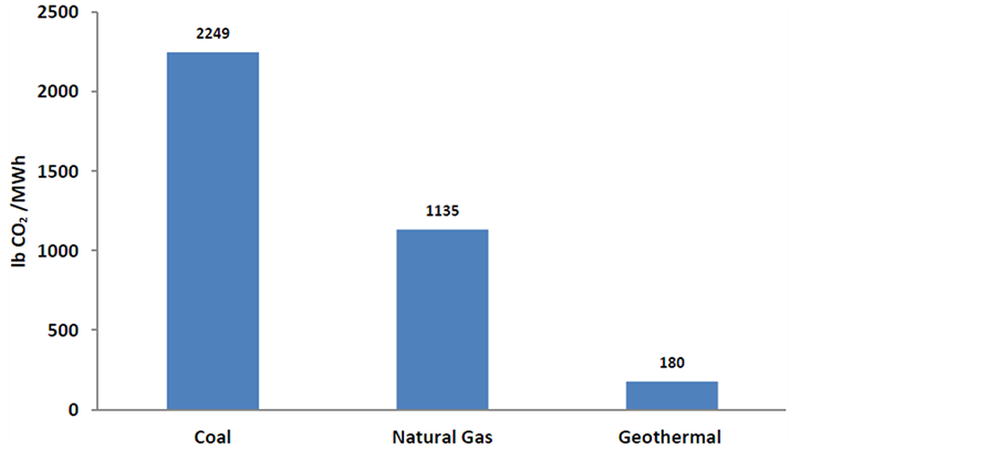
Figure 1. Comparison of CO2 emissions by coal, natural gas and geothermal source.
This paper discussed the progress on carbonation filling achieved by tests and searched for fast reaction methods using exhaust gas containing waste sulfur and carbon gases at the stack of Power Stations. Other alkaline sources containing calcium, magnesium and magnesium salts, supercritical CO2, water slurry, and additives were searched for optimum sequestration methods and also in order to enhance mineral reactivity; and in analyzing the structural changes to identify reaction paths and potential barriers. Carbonation liquid and gaseous products may change to near 20% - 45% yield performances by time increase from 1 hr to 6 hrs.
2. CO2 Sequestration and Mineralization
Options for storing CO2 in deep underground geological formations need adequate porosity and thickness for storage capacity and permeability for gas injection are critical. The storage formation should be capped by extensive confining units such as shale, salt caves or anhydrite beds to ensure that CO2 does not escape into overlying, shallower rock units and ultimately to the surface. Geological storage of CO2 requires compression of CO2 to allow injection. This is done by compressing the CO2 to a dense fluid state known as “supercritical”. This supercritical state is achieved by exposing the CO2 to temperatures higher than 31.1˚C and pressure greater than 73.9 bars. The density of CO2 will increase with depth, until about 800 meters or greater, where the injected CO2 will be in a dense supercritical state [5] -[14] .
The mineral carbonation, a process of converting CO2 into stable minerals—mineralization has been studied extensively to capture and store CO2. However, most of the mineral carbonation studies have been largely investigated at lab scale. Preliminary and pilot scale studies for accelerated mineral carbonation (AMC) were conducted at one of the largest coal-fired power plants (2120 MW) in the USA by reacting flue gas with fly ash particles in a fluidized bed reactor. In the preliminary experiments, flue gas CO2 and SO2 concentrations decreased from 13.0% to 9.6% and from 107.8 to 15.1 ppm, respectively, during the first 2 min. of reaction. The flue gas treated by fly ash particles, even mineralization hold high mercury (Hg) concentration of 0.22 mg/kg in flue gas [15] -[18] .
Geothermal brine waters utilization and using of CO2 as feed material in mineral carbonation produce various environmentally benign products. However, many challenges to any solution include technical feasibility, economic viability, environmental soundness and long term sustainability for mineralization of CO2 [19] -[23] .
3. Mineral Sequestration Method of CO2
Mineral sequestration involves the reaction of CO2 with minerals to form geologically stable carbonates. This mineralization of CO2 was searched by different studies using various materials [23] -[26] . General and specific global mineral carbonation reaction pathway is shown in Figure 1.
Mineral carbonation reactions are known to geologists and occur spontaneously on geological time scales. For example, the reaction of CO2 with common mineral silicates to form carbonates like calcite and magnesite or calcite is exothermic and thermodynamically favored.
The family of reactions represented by Reaction 1 has the potential to convert naturally occurring silicate minerals to geologically stable carbonate minerals and silica. This process follows natural chemical transformations such as weathering of rocks to form carbonates over geologic time periods. Reaction 2 illustrates the transformation of the common silicate mineral serpentine, Mg3Si2O5(OH)4, and CO2 into magnesite, MgCO3, silica and water. Using this ideal case, one ton of serpentine can dispose of approximately one-half ton of CO2. Reaction 3 illustrates the transformation of forsterite, which is the end member of the common silicate mineral olivine. One ton of olivine can dispose of approximately two-thirds of a ton of CO2. Again, the reaction is exothermic and releases 90 kJ/mole of CO2.
![]() (1)
(1)
![]() (2)
(2)
 (3)
(3)
A conceptual illustration of the projected Fly ash mineralization process is presented in Figure 2. As illustrated, CO2 from one or more power plants is transported to a carbonation reactor, combined with fly ash slurry tank and held at the appropriate reaction conditions until the desired degree of carbonation is reached. Careful
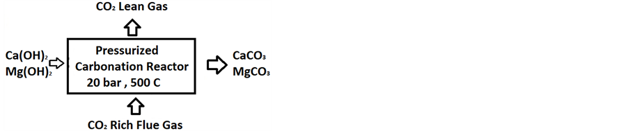
Figure 2. General chemical mineralization path.
control of solution chemistry yielded olivine conversions of 90% in 24 hrs and 83% within 6 hrs. The most recent results show further modifications of the same basic reaction can achieve 65% conversion in 1 hour and 83% conversion in 3 hours. A recent literature review indicated that weak carbonic acid treatments had also been suggested for Mg extraction in the prior literature [12] . Carbonation tests performed at ARC employing heat pretreated serpentine have resulted in up to 83 % conversion in 30 minutes lower than 115 bars [13] . Indeed, by increasing sodium bicarbonate concentration the carbonation reaction of serpentine can reach 62% completion under 50 bars [27] -[29] .
Then products of the reaction, which might be slurry of carbonated minerals and residues and lean gas CO2 in aqueous, are separated. The residual CO2 is recycled. Useful materials are collected for construction works or the carbonated materials and residue are returned to the mine site. Almost calcium and magnesium oxide (MgO) content in the magnesium silicate ore mineral of 40% and 60% - 70% chemical efficiency of the carbonation reaction; mass balance of Equation (1). A 100 MW power plant in Şırnak-Silopi, generating approximately 200 tons/day of CO2, would require just over near 80 tons/day of calcium and magnesium containing fly ash. Several fly ash types in Turkey containing sufficient calcium and magnesium oxide quantity in silicate mineral to provide raw materials for the mineral carbonation.
4. Experimental Work
In this research, representative specimens the different types of Turkish fly ashes Soma, Yatağan and Afşin were classified to calcium content by chemical analysis. Gas samples of 10 - 20 kg tubes from each different coal power stations were used. Chemical analysis of the fly ash used in the experiments is given in Table 1. Chemical reactivity of fly ash sources as lime compound is given in Table 1. Ashes contain various alkali elements. Substantial fractions of these elements in springs could be lost during clay rock pores leak. Even 50% - 60% of arsenic, lead, manganese, mercury and selenium could be removed by salt transforming in cooling.
Turkish fly ash was reacted by waste gas in the process reactor (Figure 2) and solution distributions were investigated at each stage of sequestration. Screen analysis of Turkish fly ash samples were made by standard Tyler Screens regarding ASTM 4749 and particle size distributions and normal distributions of Turkish fly ash samples are respectively illustrated from Figure 3. Particle Size Distribution and Normal Size Distribution of Turkish fly ashes used in gaseous CO2 medium changed mainly surface pore reaction process. Main reactive ash structure is widely distributed and porous structures are associated with clay minerals. Coarse alkali oxides are also seen. Screen analysis of carbonate samples were made by standard Tyler Screens regarding ASTM 4749 and particle size distributions and normal distributions of lignite samples are respectively illustrated from Figure 4. Specific surface area yielded carbonate crystals was about 2.6 - 4.2 m2/g determined by BET surface analyzer and highly sufficient in order to react with gaseous CO2. As seen from Figure 4, 80% of weights of carbonates size distribution under 4 mm. In order to determine strengths in cure through a concrete block, the laboratory scale studies were conducted at a controlled medium.
From these results, we designed and developed laboratory scale filling unit consisting a mold (0.3 mΦ × 0.7 m) to mixture mineralized cement with cement/ash rate 5/1 and cement/water slurry rate at about 2/7. The decanter unit separates ash and fine aqueous water in molding. The cured at 28 days effect of fly ash and shale were provided higher strengths in slurry through a concrete block. The laboratory scale studies were conducted at a controlled pressure.
5. Results and Discussion
Turkish Fly ashes and Mine Waste Shale thrown as waste in Şırnak City of Turkey were used with foam con

Table 1. Chemical analysis of Turkish fly ash.
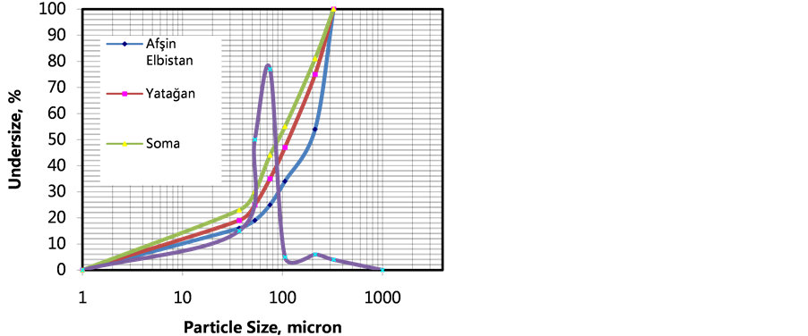
Figure 3. Particle size distribution and normal size distribution of fly ash.
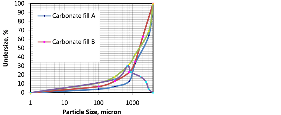
Figure 4. Particle size distribution and normal size distribution of carbonate fillers.
crete. Waste mixture at certain proportions decreasing instead of cement used, fine aggregate in specific proportions decreasing instead of fly ash used improved mechanical strength and porosity. Even fine aggregate reducing porosity rather than fly ash, such as using three different methods were performed in foam concrete production. Effects on mechanical properties of fly ash in concrete were studied intensively. Uniaxial and triaxial compression strength of foam concrete landfills was carried out in the ELE type laboratory press.
The purpose of this study, in ready-mixed foam concrete industry, Şırnak Coal Mine Waste shale and fly ash contribution were widely determined and effective amount of clay and ash on workability of the foam concrete and the curing time were determined. For this purpose in the mixture of foam concrete fine aggregate of 5%, 10%, 20% and 65% shale and 5%, 10%, 20% and 30% of fly ash were prepared with the foam concrete mixture substitution. In conclusion, depending on the amount used the fly ash in foam concrete, workability significantly changed and even significant the pressure increase.
Compression strength values depending on the amount of fly ash and foam substituent were reduced. Also in the mixture of fly ash used concrete curing time depending on the amount of substitution was found to reduce the porosity.
Soil rock samples were taken from the construction foundation and strengths with the bulk density are shown in Table 2. For determination of rock types based on logging were carried out and the results showed poor and good rock classification as given in Table 2.
In this study, the strength and the mechanical parameters of 10% mixture shale and foam concrete were determined and are given in Table 2. The amount of fly ash on properties of water discharges in the landslide risk area were also investigated and briefly given in Table 2. Some control coal mine rooms were accessed in order to optimize filling use with carbonation fills as given in Figure 5. The yield strengths for fly ashes and shale fill without foam concrete filling with different Turkish fly ash were tested and the results of samples were given in Figure 6. At shale fill blocks the strength increased to the higher levels of 19 MPa. At carbonate filling foam concrete blocks the strength slightly raised to about 16 MPa.
In experiments with different filler types for yield strengths of fly ash and shale fill within foam concrete filling were tested and the results of samples were given in Figure 7. At shale fill blocks the strength increased to the higher levels of 19 MPa. At carbonate filling with foam concrete blocks the strength yields are seen satisfying unit resistance to in-situ stress in filling rate of 40% - 50% with foam concrete.
Table 2. Effect of mixture rates used on filling strength yield and water discharge in 28 curing time.
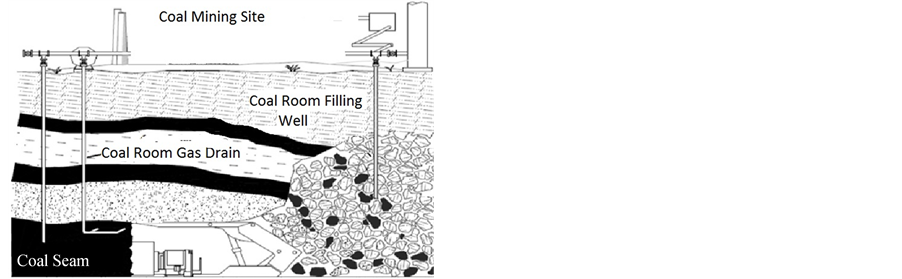
Figure 5. Filling of carbonates coal mine room.
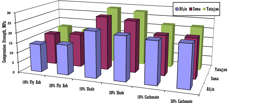
Figure 6. Effect of mixture rates in 28 curing time used on filling strength yield without foam concrete.
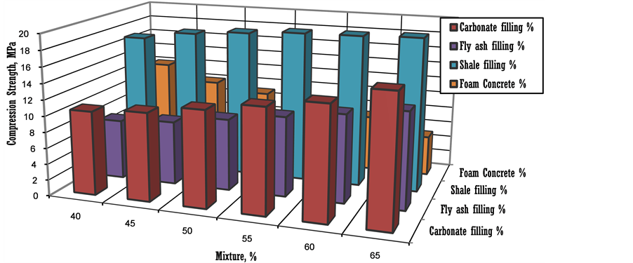
Figure 7. Effect of mixture rates in 28 curing time used on filling strength yield with foam concrete.
In the carbonation experiments, the experimental conditions are calculated on the basis of the gas composition in the ambient state. So neither the contained water vapor nor the others are taken into account. Carbonation solid products may change to filler strength of 45% - 20% by time increase from 14 days to 28 days.
6. Conclusions
Various faces characterize the mining open rooms in coal mining in Şırnak Coal Mine excavation seam of Lower Eocene that had been named formations which include the Cudi Mountain Formation. It is one of the four lateral equivalents of the Siirt Group and consists of shale and marls with abundant limestone. In this paper, we report on the filling matter on settlement and strength of the Coal Mining Rooms during operation. Settlement values were satisfying in the formation from nine outcrop cross sections in central and northern Coal Mine Site. The total strength (σ) values and Rock-Classification analysis showed that this formation had preserved coal rooms in operation. Locally, such as at 50 - 75 mm are very high. These values are reliable to the structural framework in subsiding during the excavation of the coal. Laboratory analysis showed that this total strength (σ) is very great in these shale carbonate compounds. Our results exposed that the fly ash use in carbonation and filling in coal rooms were strong as other fillers by an open site tests as revealed by the relative stability of the Shale fill (37% - 43%), Carbonate fill (26% - 31%), and Fly ash-Foam Concrete fill (30% - 34%).
The compounds for all the samples were good preservations of the roof formation which has been evidenced by the high abundance. Under preserved conditions in central Mine Site, we interpreted that the development of mine had been induced by water flow in winter climate. These results in concord with the structural and the settling where the roof formation in central deposited coal excavation area in highly subsiding separated from the open west hill site. In northern excavation site, eastern upwelling waters enhanced primary settlement and the development of abnormal conditions.
Acknowledgements
The author would like to thank Mining Engineering Department of Süleyman Demirel University.
References
- Minchener, A.J. and McMullan, J.T. (2007) Clean Coal Technology. IEA Coal Research Ltd., London.
- IEA (2012) World Energy Outlook.
- TKI (2009) Lignite Coal Report. The Turkish Ministry of Energy, Energy Department.
- TTK (2009) Hard Coal Report. The Turkish Ministry of Energy, Energy Department.
- Metz, B., Davidson, O., de Coninck, H.C., Loos, M. and Meyer, L.A. (2005) IPCC Special Report on Carbon Dioxide Capture and Storage. Prepared by Working Group III of the Intergovernmental Panel on Climate Change. Cambridge University Press, Cambridge, United Kingdom and New York, 442.
- Stangeland, A. (2007) A Model for the CO2 Capture Potential. International Journal of Greenhouse Gas Control, 1, 418-429. http://dx.doi.org/10.1016/S1750-5836(07)00087-4
- Solomon, S. (2006) Carbon Dioxide Storage: Geological Security and Environmental Issues—Case Study on the Sleipner Gas Field in Norway, Bellona Foundation, Oslo. http://www.bellona.no/artikler/notat_solomon
- Torp, T.A. and Gale, J. (2004) Demonstrating Storage of CO2 in Geological Reservoirs: The Sleipner and SACS Projects. Energy, 29, 1361-1369. http://dx.doi.org/10.1016/j.energy.2004.03.104
- CSLF (2004) Considerations on Legal Issues for Carbon Dioxide Capture and Storage Projects, Report from the Legal, Regulatory and Financial Issues Task Force.
- DOE (1998) Vision 21, Clean Energy for the 21st Century. U.S. Department of Energy, Office of Fossil Energy DOE/FE-0381. www.fetc.doe.gov/publications/brochures/
- Oldenburg, C., et al. (2001) Process Modeling of CO2 Injection into Natural Gas 2 Reservoirs for Carbon Sequestration and Enhanced Gas Recovery. Energy & Fuels, 15, 293-298. http://dx.doi.org/10.1021/ef000247h
- Stevens, S., et al. (2001) Sequestration of CO2 in Depleted Oil and Gas Fields: Global Capacity, Costs, and Barriers. In: Williams, D.J., Durie, R.A., McMullan, P., Paulson, C.A.J. and Smith, A.Y., Eds., Proceedings of Greenhouse Gas Control Technologies 5th International Conference (GHGT-5), Interlaken, 278-283.
- Stevens, S., et al. (1999) CO2 Sequestration in Deep Coal Seams: Pilot Results and Worldwide Potential. Proceedings of Greenhouse Gas Control Technologies 4th International Conference (GHGT-4), Interlaken, 175-180.
- Myer, L. (2003) Sensitivity and Cost of Monitoring Geologic Sequestration using Geophysics. In: Gale, J. and Kaya, Y., Eds., Proceedings of Greenhouse Gas Control Technologies 6th International Conference (GHGT-6), Elsevier Science Ltd., Amsterdam, 1, 377-382,
- Zweigel, P., Hamborg, M., Arts, R., Loethe, A., Sylta F. and Tomeras, A. (2000) Prediction of Migration of CO2 Injected into and Underground Depository: Reservoir Geology and Reservoir Modeling in the Sleipner Case (North Sea), In: Williams, Durie, R.A., McMullan, P., Paulson, C.A.J. and Smith, A.Y., Eds., Proceedings of Greenhouse Gas Control Technologies 5th International Conference (GHGT-5), 13-16 August 2000, Cairn, 360-365.
- Pacala, S. (2003) Global Constraints on Reservoir Leakage. Proceedings of Greenhouse Gas Control Technologies 6th International Conference (GHGT-6), Elsevier Science Ltd., Amsterdam, 267-272.
- Hepple, R. and Benson, S. (2003) Implications of Surface Seepage on the Effectiveness of Geologic Storage of Carbon Dioxide as a Climate Change Mitigation Strategy. Proceedings of Greenhouse Gas Control Technologies 6th International Conference (GHGT-6), Elsevier Science Ltd., Amsterdam, 261-266.
- Lindeberg, E. (2003) The Quality of a CO2 Repository: What Is the Sufficient Retention Time of CO2 Stored Underground. Proceedings of Greenhouse Gas Control Technologies 6th International Conference (GHGT-6), Elsevier Science Ltd., Amsterdam, 255-260.
- Rubin, E. and Rao, A. (2003) Uncertainties in CO2 Capture and Sequestration Costs. Proceedings of Greenhouse Gas Control Technologies 6th International Conference (GHGT-6), Elsevier Science Ltd., Amsterdam, 1119-1124.
- Seifritz, W. (1990) CO2 Disposal by Means of Silicates. Nature, 345, 486. http://dx.doi.org/10.1038/345486b0
- Kojima, T., Nagamine, A., Ueno, N. and Uemiya, S. (1997) Absorption and Fixation of Carbon Dioxide by Rock Weathering. Energy and Conservation Management, 38, S461-S466. http://dx.doi.org/10.1016/S0196-8904(96)00311-1
- Gunter, W.D., Perkins, E.H. and McCann, T.J. (1993) Aquifer Disposal of CO2-Rich Gases: Reaction Design for Added Capacity. Energy Conversion and Management, 34, 941-948. http://dx.doi.org/10.1016/0196-8904(93)90040-H
- Lackner, K.S., Wendt, C.H., Butt, D.P., Sharp, D.H. and Joyce, E.L. (1995) Carbon Dioxide Disposal in Carbonate Minerals. Energy (Oxford), 20, 1153-1170.
- O’Connor, W.K. (1998) Investigations into Carbon Dioxide Sequestration by Direct Mineral Carbonation. Presentation at 2nd Meeting of Mineral Sequestration Working Group, 3 November 1998, Albany, p10.
- Butt, D.P., Lackner, K.S. and Wendt, C.H. (1997) A Method for Permanent Disposal of CO2 in Solid Form. World Resource Review, 9, 324-336.
- Drägulescu, C., Tribunescu, P. and Gogu, O. (1972) Lösungsgleichgewicht von MgO aus Serpentinen durch Einwirkung von CO2 und Wasser. Revue Roumaine de Chimie, 17, 1518-1524.
- O’Connor, W.K., Dahlin, D.C., Nilsen, D.N., Walters, R.P. and Turner, P.C. (2002) Carbon Dioxide Sequestration by Direct Mineral Carbonation with Carbonic Acid. Presentation at 27th International Technical Conference on Coal Utilization & Fuel Systems, 6-9 March 2000, Clearwater, 819-830.
- Goff, F., et al. (1997) Preliminary Investigations on the Carbon Dioxide Sequestering Potential of Ultramafic Rocks. Los Alamos National Laboratory, Los Alamos, LA-13328-MS.
- Goldberg, P.M., et al. (2000) CO2 Mineral Sequestration Studies. GlobeEx 2000, August, Las Vegas.