Engineering
Vol. 2 No. 11 (2010) , Article ID: 3163 , 4 pages DOI:10.4236/eng.2010.211107
Design and Modeling of Femto Air Bearing Slider
1School of Mechanical & Aerospace Engineering, Nanyang Technological University, Singapore City, Singapore
2Data Storage Institute, (A*STAR) Agency for Science, Technology and Research, Singapore City, Singapore
3The Australian School of Advanced Medicine, Macquarie University, Sydney, Australia
E-mail: mykng@ntu.edu.sg
Received August 6, 2010; revised October 11, 2010; accepted October 12, 2010
Keywords: Femto Air Bearing, Performance, Slider Design, Modeling, Simulation, Optimization
ABSTRACT
This paper presents the studies of the performance of an improved femto air bearing slider which is optimized based on the past studies and effort. The flying characteristics performance of this novel femto slider is relatively stable over different radii. This optimized slider achieved a flying height of 3 nm, with variation of about 0.2 nm. The variations for pitch and roll values are 6 µrad and 0.9 µrad respectively. In the studies for the effect of side rail on flying characteristics, it was found that there exists transition of pitch value when the side rail is located very close to the leading edge. The modulation of flying height reduces greatly when the areas of double shallow steps increase. The roll variation reduces when the flat double shallow steps profile is modified into a “V-Shape” profile.
1. Introduction
To enhance capacity and performance in meeting the high demands of hard disk drives (HDDs) nowadays, the flying heights of the sliders have to be very low and flying stability is therefore critical for the air bearing sliders design. Pitch is mainly affected by step recess; roll is affected by side rails or side pads while the trailing pad is correlated to the pitch and flying height. The negative pressure design can improve slider performance with high positive pressure generation and therefore result in high air bearing stiffness at the trailing pad in particular. This allows the slider to follow the waviness of the disk surface better. When the step rail area is increased, there is an increase in pitch with higher positive pressure force at the increased step area. There is also an increase in the flying height due to larger air bearing resultant force. When the area of the trailing edge rail (trailing pad) is increased, the flying height increases and pitch reduces. In track seeking simulation, it is found that the addition of side pads (beside the trailing pad) increases the roll stiffness which stabilizes the slider. The amplitude of the slider oscillation depends on the air bearing stiffness. The rate of decay of the oscillations depends on the damping ratio of the slider.
Liu et al’s experimental result on flying height modulation due to disk waviness suggests a better flying height modulation performance using femto slider as compared to pico slider [1]. By introducing a mini high-pressure trailing pad and double shallow steps, the performance is significantly improved due to a sharp pressure profile footprint is achieved, thus increases the slider’s dynamic response. A negative pressure slider design has the best performance with low sensitivity to skew and manufacturing tolerances. However, this negative pressure slider design has larger altitude sensitivity which can be reduced by optimizing the pitch angle through rail shaping [2]. Two sliders with shallow step air bearing pads are simulated and compared with experimental results. Wada et al conclude that to achieve good flying stability in a very low flying condition, high air bearing stiffness is necessary [3]. For dynamic simulation, three sub-25nm flying height sliders are simulated to determine their suitability for near contact recording. The results show that a slider with higher air bearing stiffness and smaller slider will decrease the flying height modulation of the slider. During track seeking process, the flying height modulation is found to be dependent on the effective skew angle, seeking velocity, seeking direction and the roll motion caused by the inertia of the moving head. Lu et al report that a larger roll stiffness and roll damping ratio can produce a smaller roll motion effect on the flying height modulation [4]. Lee et al studied the effect of head parameters on the take-off velocity of a slider and they found that an increasing head crown significantly reduced the take-off velocity of the slider. The skew angle and suspension preload were also found to affect the take off velocity [5].
Thornton, Nayak and Bogy investigated the flying height modulation due to disk waviness of two low flying height air bearing sliders. They found that for relatively long wavelength of disk waviness, the flying height modulation is dependent on the length of the slider. But for disk waviness of the order of the sliders’ length, the flying height modulation is dependent on the sliders’ attitude (pitch angle) and air bearing surface design (pressure distribution) [6]. Xu et al studied the dynamic response and flying height modulation due to disk waviness of a flying 5-pad femto slider with negative pressure. The results show that the pads’ positions can have an effect on the waviness following ability of the slider. The waviness following ability can also be improved by reducing the components of waviness with short wavelength [7]. There are also some studies regarding the Dynamic Load/Unload (L/UL) technology. Zeng and Bogy studied and simulated the L/UL process of four typical sub-ambient slider designs. They proposed that the negative pressure regions of the sliders should be maintained near the center line and the trailing edge to improve the performance [8]. They also found that loading process is much smoother at low RPM. The loading velocity did not greatly affect the process. Besides, a larger dimple preload can reduce the pitch vibration during unloading. Park et al proposed a method to control the unloading input position to improve L/UL performance. By controlling the unloading instant based on the disk vibration characteristics, we can significantly reduce the number of slider-disk contacts [9]. Jeong and Bogy [10] proposed that the lift-off force should be reduced to improve the load/unload performance. Unload performance was found to be affected by the air bearing surface design, disk RPM, unload velocity, pitch static attitude and ramp profile. While load performance was found to be affected by the air bearing surface design, disk RPM, pitch static attitude, roll static attitude, and dimple preload. Smith et al studied the unload performance of three sub-ambient slider air bearings with different suction forces [10]. One of the sliders exhibited a positive net loading force throughout the entire unloading process [11]. It was also found to exhibit an increasingly positive pitch angle and a limited roll angle during the unload process. It was believed that these factors contributed to a well designed slider which possessed good load/unload performance. Tanaka, Kohira and Matsumoto’s group also studied the unloading process of three different sliders but with different negative pressure force. The results show that the unloading process became smoother if the negative pressure force was smaller. However, the flying stability will be reduced if negative pressure force is smaller. Therefore, there will be a trade off between the flying and unloading stability conditions [12]. Weissner and Talke did an experimental evaluation on the load/unload dynamics for two low flying pico sliders and found that a smaller pull off force led to an easier unloading process. The results also show that there is a higher possibility of slider-disk contact if the load velocity is larger [13].
The aim of this project is to study and gain an understanding on air bearing design strategy. A new air bearing slider which meets both static and dynamic simulation requirements will be proposed based on the simulation results obtained by the previous researchers. The evaluation of the air bearing slider’s performance is done using the commercial simulation software CMLAir [14]. The effects of several key parameters such as rail profile, recess height, altitude, and disk rotation speed will also be investigated to optimize the air bearing slider.
2. Static Simulator
The governing equation for the gas lubricated bearing is the Reynolds equation, which can be written as:
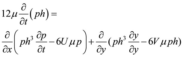
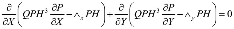
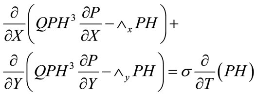
In the above equation, p is the pressure, h is the local clearance,  is the viscosity of air, U and V are the disk velocity components of the moving surface in the x and y directions. In deriving this equation, the z velocity component and the inertial forces and the body forces are negligible. It is also assumed that the pressure is constant across the film thickness since film thickness is much smaller than the lateral dimensions. The film thickness is assumed to be small in the Reynolds equation, but it has to be large compared to the mean free path of the air (about 64 nm under standard conditions) in order for the non-slip condition to be valid. Originally the non-slip boundary condition is applied on both surfaces of the slider bearing. However, the displacement between the slider and the disk (< 10 nm) has recently become much smaller than the mean free path of the air. Thus the non-slip condition is not applicable anymore and the rarefaction effect has to be considered. A few types of slip correction models were introduced for this purpose, such as the continuum model, the 1st order slip model, 2nd order slip model and Fukui-Kaneko model. These slip correction models were developed based on the slip boundary condition. For slider-disk displacement as low as 10nm, the FK model is commonly used. This molecular gas lubrication model which is developed by Fukui and Kaneko is based on the linearized Boltzmann equation. The non-dimensional generalized Reynolds equation is used to find the steady state pressure distribution of the slider at every point of the grid. The expression is
where 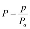 = non-dimensionalized pressure
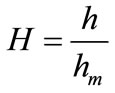 = non-dimensionalized bearing clearance
 = non-dimensionalized coordinate in the slider bearing width direction
 = non-dimensionalized coordinate in the slider bearing length direction
 = ambient atmospheric pressure
 = reference displacement at the trailing edge center
L = slider’s length
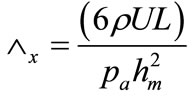 = bearing numbers in the x direction
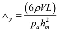 = bearing numbers in the y direction
U = disk velocity component in the x-direction
V = disk velocity component in the y-direction
Q is the flow factor, and assumes different forms depending on the type of correction model used,
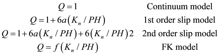
where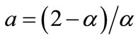 ,
,  is the accommodation factor,
  , is the Knudsen number and λ is the mean free path of air.
2.1. Dynamic Simulator
For the dynamic simulation, the following Reynolds equation is used as the governing equation. The only difference between this equation and the previous one is that there is an unsteady term in the equation.
where T = ωt = non-dimensionalized time
ω = angular frequency
 = squeeze number
All the other terms are similar with the Reynolds equation of the static simulator. The dynamic simulator solves both the Reynolds equation and the equations of motion of the head-disk assembly at the same time. The 2D equations of motion are
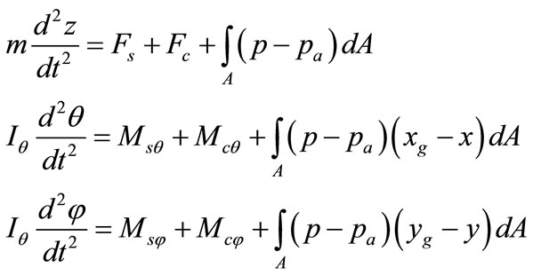
where m is the mass of the slider, z is the vertical spacing, θ and  are the pitch and roll angles,
  and
and  are the moments of inertia of the slider,
  and
and  show the position of the slider’s center of gravity.
 ,
,  and
and  are the force and moments due to the suspension.
 ,
,  and
and  are the force and moments on the slider due to the disk.
3. Initial Air Bearing Surface Design & Performances
The femto air bearing slider in this study consists of small leading edge pads or side rails to limit the pitch value to be within the optimal range. Besides, smaller pads size allows a smaller positive force and thus contributes to a lower flying height. Side pads are introduced to create higher roll stiffness so that the roll variation will be moderate during the track seeking process in dynamic simulation. This slider has a large negative pressure region with reduced resultant force and less sensitivity to skew & manufacturing tolerances. Double shallow steps concept is applied in this slider design to create a sharp pressure profile for high trailing pad air bearing stiffness. Small trailing pad size permits the slider to follow the disk waviness closely. Figure 1 shows the rail profile of this femto slider.
The flying characteristic of the original slider is shown in Table 1. The minimum and maximum pitches are 111.97 µrad and 119.44 µrad respectively. From 16 mm to 27 mm radii, the modulation of pitch is about 6.67%, and it is in acceptable level. The roll variation is also within the acceptable range of –5 µrad to +5 µrad. Flying heights at middle point of trailing edge at different radii are small but the modulation is about 11.4% and it exceeds the acceptable modulation percentage of 10%.
The normalized pressure profile is included in Figure 2.
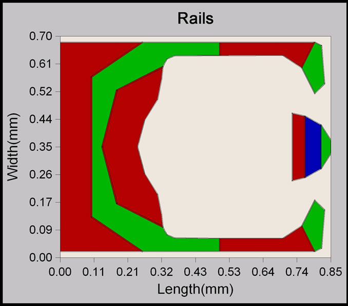
Figure 1. Initial rail profile design of air bearing surface.
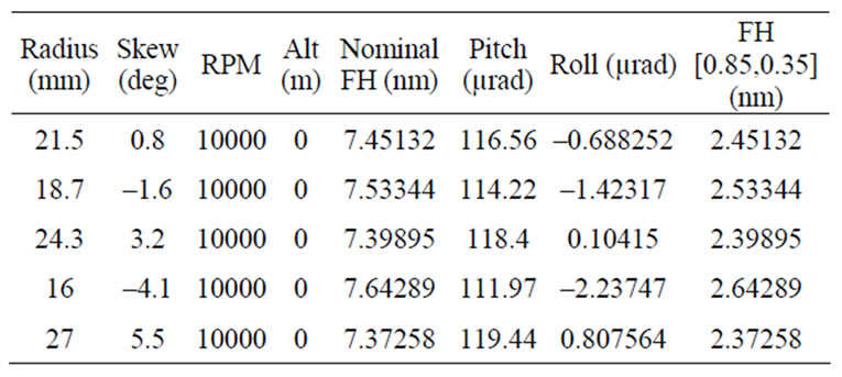
Table 1. Flying characteristics results of original slider design.
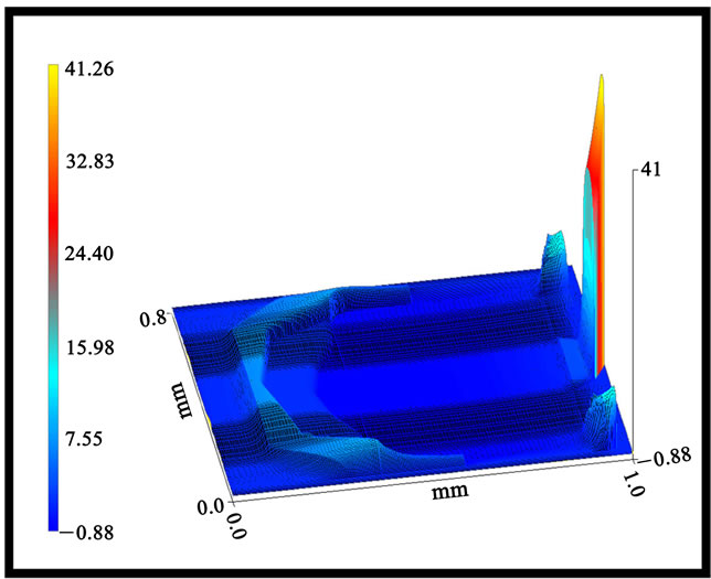
Figure 2. Initial air bearing slider normalized pressure profile.
The normalized tip pressure is 41.26. The high pressure experienced at the middle point of trailing edge enables the slider to fly at a very low level. The positive pressure profile of side rails contributes to a relatively large pitch. Therefore, to reduce the pitch value, the rail size must be reduced. In this way, the total positive force is decrease and hence smaller pitch and flying height can be achieved.
4. Effect of Side Rail on Flying Characteristics
Four different profiles of rail area as shown in Figure 3 are introduced to study the effect of side rail on flying characteristics. Table 2 presents the simulated slider performances at radius 21.5 mm and skew of 0.8°. It is observed that the change in pitch is more significant than the roll and flying height. The larger the rail area, the greater the pitch will be. However, this does not apply in case A. From cases B to D, the pitch is decreasing while the flying height is increasing. When the area of the side rail is reduced, less positive force is generated; this causes a shift of positive force centre towards the trailing edge, reducing the pitch and increasing the flying height of the slider.
The side rail area is the largest for slider case A, but the pitch value is not the highest as compared to the other three cases. To study this observation, a slider with side rail area in between cases A and B was constructed as indicated in Figure 4. The results indicate that the pitch value of case Z produces the highest value compared to cases A and B. The explanation is illustrated in Figure 5. For slider A, where the side rail is closer to the leading edge, the amount of airflow in between the slider-disk interface is less. Therefore, small amount of air is forced through and squeezed in between the small flying height. Less pressure is thus generated and the corresponding positive force in this region is smaller too. This causes a shift of positive force centre towards the trailing edge and leads to a smaller pitch. The overall reduction of positive force causes the low flying height. This explains the observation of lower pitch and flying height values.
For design case Z, larger amount of air is allowed to flow between the interfaces from leading edge. When the air reaches the rail, it is forced and squeezed into an even smaller spacing; higher air pressure is therefore created. The positive force generated will also be more than that of case A. The larger the rail area, more positive force will be created, the center of positive force will shift towards the leading edge, raising the pitch value. The overall increase in positive force also causes the rise of flying height. But the significant increase in pitch permits the rise of flying height to be smaller.
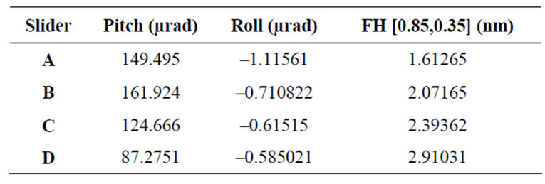
Table 2. Flying characteristics results with varying side rails area.
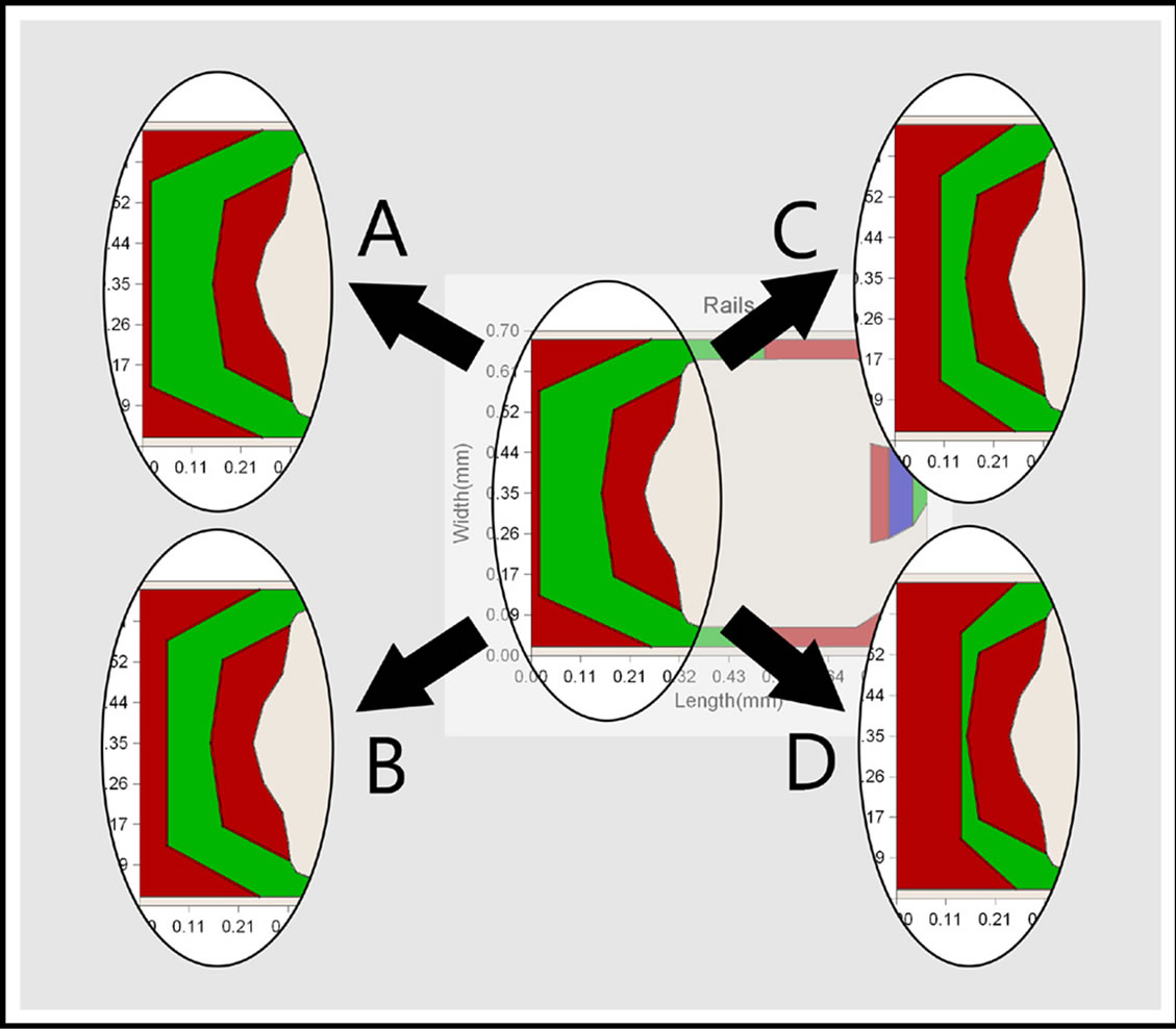
Figure 3. Choices of side rails area.
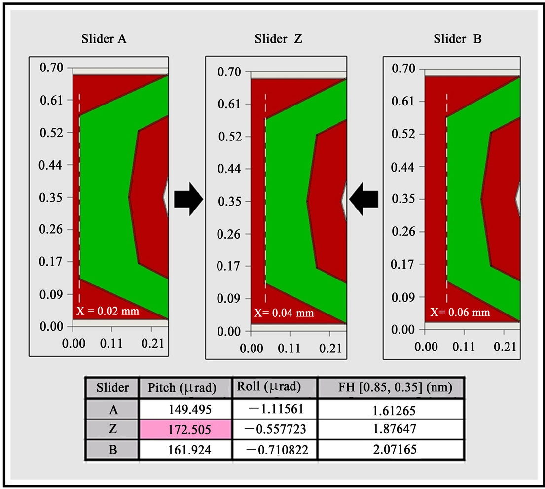
Figure 4. Modified side rail design of Slider Z and its results.
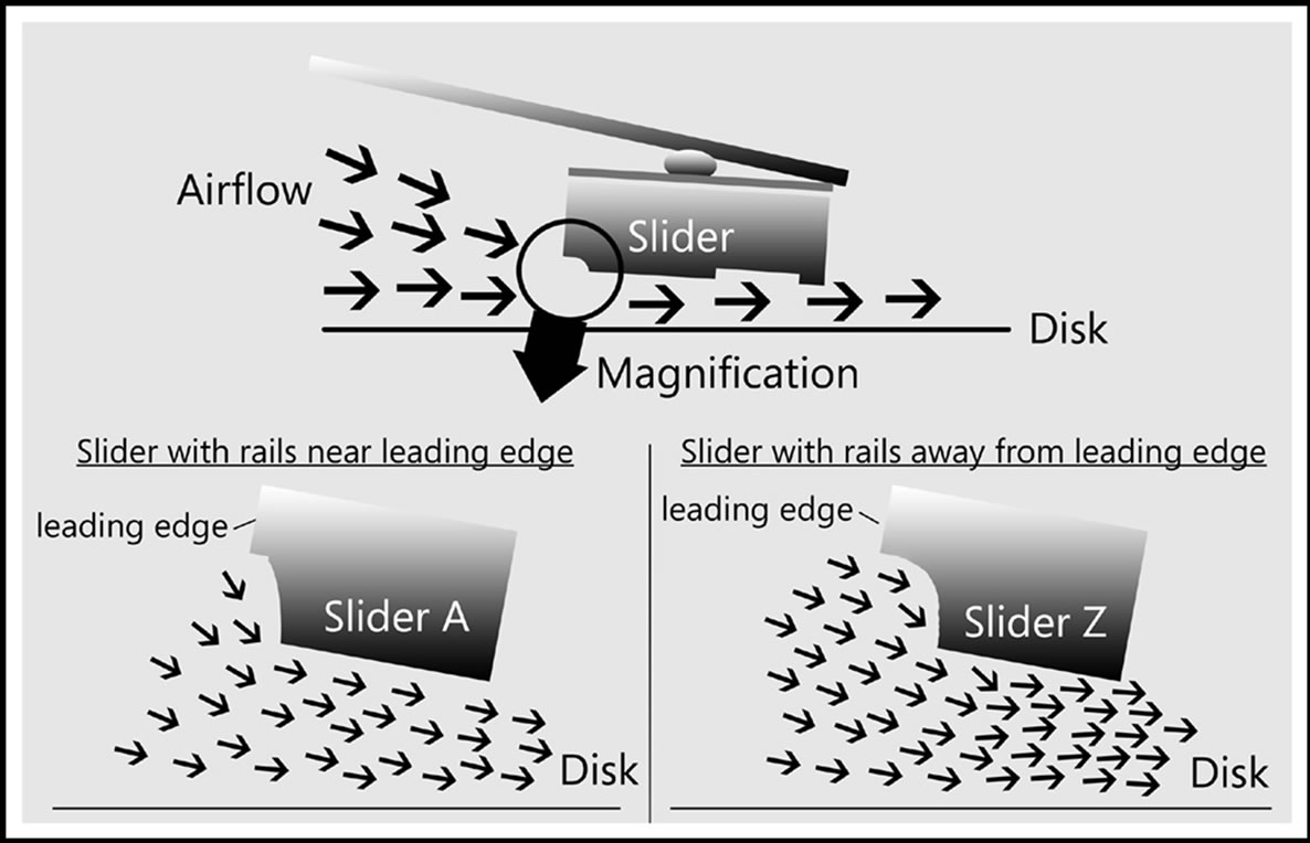
Figure 5. Comparisons between Slider A and Slider Z.
5. Effect of Double Shallow Steps on Flying Characteristics
The studies on double shallow steps consist of two recess heights: 0.15 µm and 0.06 µm.
5.1. Step with 0.15 µm Recess Height
Four different configurations (Figure 6) with the simulated results are included in Table 4. It can be observed from Table 3 that the larger the step area, the lower the flying height, and the larger the pitch value will be. It was found that the mass flow through the trailing pad and double shallow steps region are getting “lesser” when the area is increased as shown in Figure 7. The air flow path is diverted away towards two sides by the shallow step. The lesser the mass flow, the lower pressure generated on the pad, hence smaller positive force. Therefore the flying height is lower.
With a larger shallow step area, the modulation of flying height becomes smaller. This can be seen by comparing the flying characteristics results of two extreme radii (16 mm and 27 mm, which is equal to the inner and outer diameters) and tabulated in Table 4. Therefore, for this slider, to have a smaller flying height modulation, the area of this 0.15 µm step must increase.
5.2. Step with 0.06 µm Recess Height
Another four different configurations (Figure 8) and their similar results are shown in Table 5. By comparing the results of two extreme radii as in the previous case did (Table 6), it is confirmed that modulation can be minimized using a larger shallow step area.
6. Modified Slider Design
In summary, from our static design, the recess height of the step rail was specified as 0.15 μm, which gives the lower flying height and yet suitable pitch value. Base recess remains as 1.65 μm due to the good performance. This side rail design was chosen because it gives a suitable value of pitch and flying height. Step rail area was found to affect the pitch, so to lower down the pitch value, the area has to be decreased. Side pads is the factor that affecting the roll, so side pads design B was chosen because it gives the lowest roll value (the range for roll variation has to be within –5 μrad to +5 μrad).
For the trailing pad, the area cannot be too large or too small, so it was adjusted to give appropriate flying characteristics. The areas of double shallow steps were adjusted to reduce the modulation of both pitch and flying height. Besides, the tuning of overall performances of slider can also be done by modifying the double shallow steps profiles. The nominal distance of wall profile of the
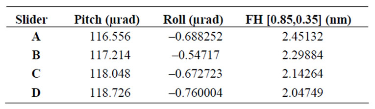
Table 3. Flying characteristics with varying area of 0.15 µm shallow step.
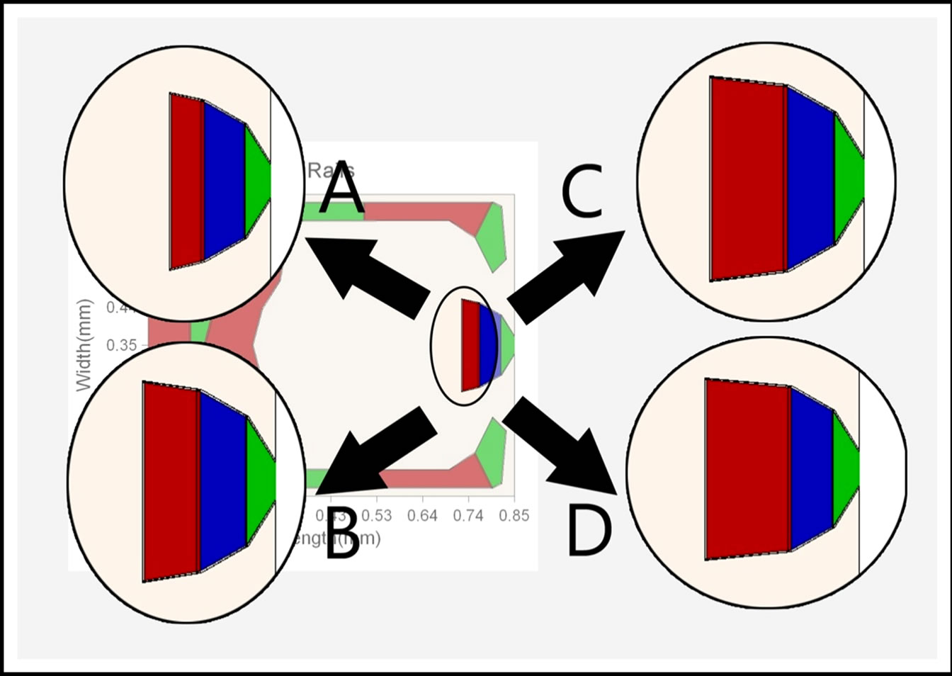
Figure 6. Changes in 0.15 µm shallow step area.
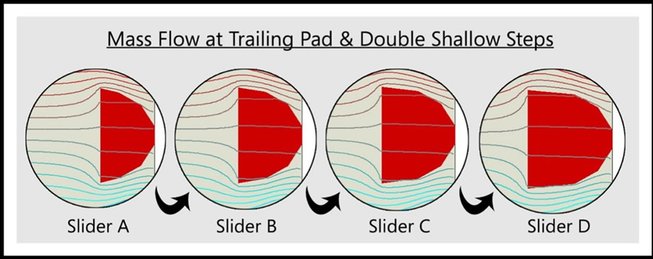
Figure 7. Mass flows between Slider A, B, C, and D.
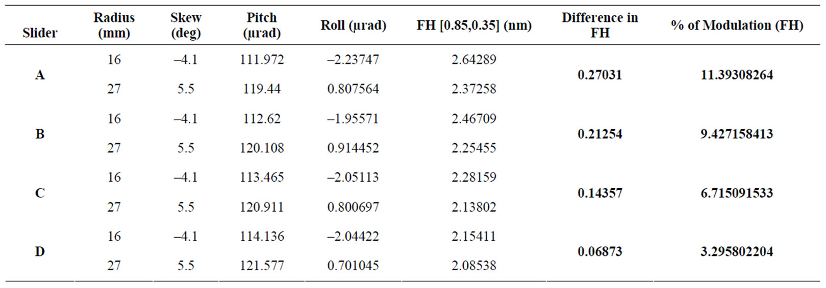
Table 4. Modulations of flying height of different sliders with 0.15 µm shallow step.
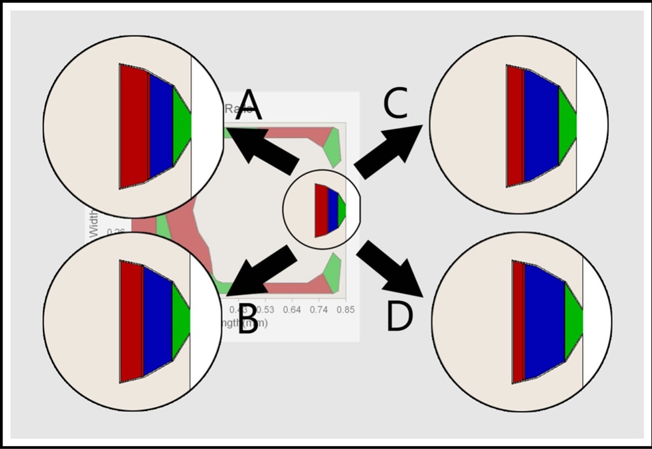
Figure 8. Changes in 0.06 µm shallow step area.
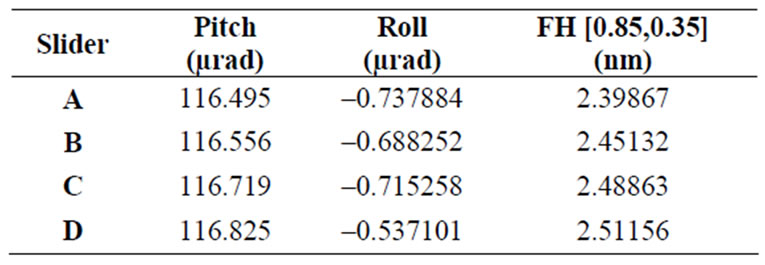
Table 5. Flying characteristics results with varying area of 0.06 µm shallow step.
step rail (red region) was defined as 2 μm while the side rails, side pads and trailing pad were 4 μm. Grid size of 289 × 289 was used. The radial positions and skews were set to five different values as shown in the Run Setup Windows below. Disk angular speed was 10000 RPM and altitude was 0m. The simulation results fulfill the femto slider’s static requirements. The pitch is within the range of 100 μrad to 120 μrad, the modulation of pitch is about 6.38%. For the flying height, the results between different radii are quite close. The modulation is about 2.17%. And it is within the range of 3 nm to 5 nm. The roll variation is also within the limitation of –5 μrad to +5 μrad. To enhance the performances of the slider, modifications were done on the double shallow steps to increase the pressure at the trailing pad and also to facilitate the mass flow. For the double shallow steps design above, the pressure generated is not high enough, i.e. the corresponding air bearing stiffness is relatively low. The flat design of steps might also obstruct the mass flow and reduce the slider performances. The modified slider design and results are shown on the following
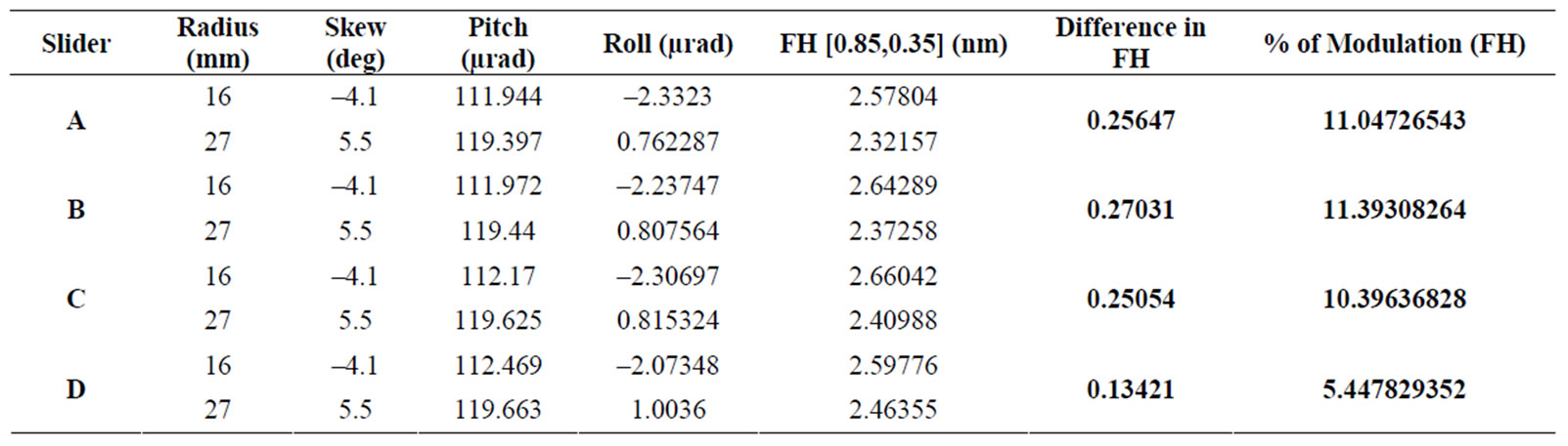
Table 6. Modulations of flying height of different sliders with 0.06 µm shallow step.
pages. Basically, all the parameters remained the same, changes were done only on the rail profile. The new rail design is shown as follows: The simulation results fulfill the femto slider’s static requirements. The pitch is within the range of 100μrad to 120μrad, the modulation of pitch is about 6.79%. For the flying height, point (0.83, 0.35) is examined. The results between different radii are quite close. The modulation is about 7.72%. And it is within the range of 3 nm to 5 nm. The modulations of pitch and flying height are within 10%. The roll variation is also within the limitation of –5 μrad to +5 μrad. The pressure profile is shown on the next page. The pressure at the peak is now higher than the previous slider. This femto slider is the finalized slider for static simulation. It was sent to dynamic simulator to examine the dynamic performances. There might be changes of slider parameters to fulfill dynamic requirements. So if there are changes, the slider will be simulated in static simulator again to verify the static performances. Only slider that meets both static and dynamic requirements can be considered good.
The air bearing slider design that fulfills the static requirements was run in dynamic simulator to study the variation of flying characteristics during track seeking process. Based on the previous studies on the effects of slider parameters, we make modifications to the initial slider design as shown in Figure 9. Table 7 presents the flying characteristics results of this slider. The slider geometry and the wall profiles remain the same as the static part, the initial flying conditions are specified as above. Four points were examined. The time step was set to 0.00025 ms and the total track seeking simulation time was set to 7 ms. In the Partial Contact Windows, Green wood-Williamson model was chosen. For the material section, Young’s Modulus is 1E + 010 Pa, Poisson’s Ratio is 0.3, Yield Strength is 1E + 012 Pa, and the Friction Coefficient is 0.3. There were no molecular forces & electrostatic forces reactions; the asperities contact was also disabled. The grid size used is 242 × 242 throughout the dynamic simulation part. In the Run Setup Windows, the Stiffness & Damping Coefficients parameters, and the Suspension Loading conditions under the Suspension tab
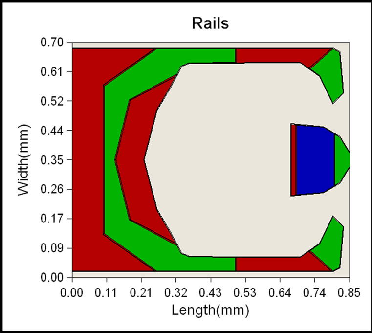
Figure 9. Modified air bearing slider (double shallow steps).
are specified as the figure shows. The entire acceleration takes 7 ms. The motion of slider was from inner diameter to outer diameter. The magnitude of acceleration was set to ±20833 rad/s2. The acceleration profile is shown below. The negative acceleration implies that the slider was accelerated radially outwards. Inline Actuator was chosen for this simulation. Disk velocity profile, disk flutter, as well as shock were disabled. It can be observed from the flying characteristics graphs that there are some oscillations between 3 ms and 4 ms, and after 6 ms. This is due to the starting and stopping the slider’s acceleration. The changes in flying height and pitch are about 0.24 nm and 2.3 μrad respectively. For the roll, the modulation is about 15 μrad, which is relatively large, but since it does not exceed 20 μrad, therefore it is acceptable. The acceleration and deceleration of the slider will result in an inertia force. It is this inertia force contributes to the roll motion effect. The magnitude of the dynamic roll change increases with the increase in the inertia force which depends on the mass of the slider. The roll change also increases if the air bearing roll stiffness is smaller. The

Table 7. Flying characteristics results of modified air bearing slider (double shallow steps).
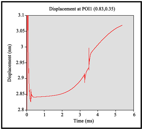
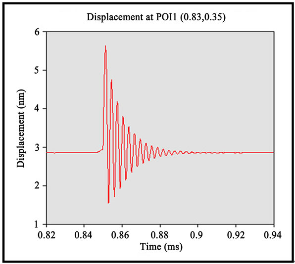
surface of the disk media is not perfectly flat. There will always be some asperities like bumps or spikes present on the disk surface. In this section, the responses of slider to an incoming asperity which is taller than the nominal flying height were examined. The time step and total time were changed to 0.00015 ms and 2 ms respectively. In this simulation, the track seeking motion was disabled. The asperity was defined to be sinusoidal in shape and of amplitude 4 nm. The X and Y positions, which are the asperity center measured from the slider’s gravitational center in disk rotation and radial directions respectively, were specified as 0.02 m and 0 m respectively. The X and Y sizes, which are the asperity footprint length in the disk rotation and radial directions respectively, were set to 1E-005 m and 0.001 m. The point by point disk track profile was disabled in this case. The shorter the time taken for oscillation to vanish, the better the results will be. From the graph, it can be observed that the oscillations of flying characteristics decay in about 0.2 ms which is less than 0.5 ms, so it is acceptable. Basically, the amplitude of the oscillations depends on the air bearing stiffness while the rate of decay of the oscillations depends on the damping ratio of the sliders. The flat profile of the double shallow steps may have certain effects on the air flow as it may obstruct the smooth air flow and causes a sudden change on the air flow. Therefore, for streamlining of air flow, another modified slider with a “V-Shape” profile is proposed in Figure 10. The static simulated results are included in Table 8. The pressure at the trailing pad of “V-Shape” design increases and the roll variation is significantly minimized due to higher roll stiffness. The dynamic performance of the slider is further examined through Track Seeking Simulation (TSS) and Response to Asperities Simulation (RAS). In TSS, an acceleration profile is defined, as shown in Figure 11. Figure 12 shows the flying characteristics results of “V-Shape” double shallow step. It can be observed that there are some oscillations between 3 ms and 4 ms, and after 6 ms. This is due to the starting and stopping the slider’s acceleration. The changes in flying height and pitch are about 0.24 nm and
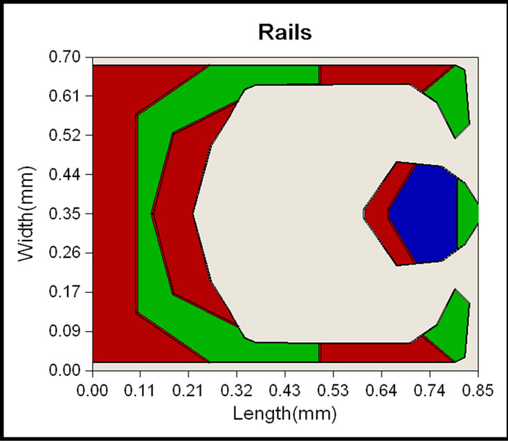
Figure 10. Modified air bearing slider (“V-Shape” double shallow steps).
2.3 µrad respectively. For the roll, the modulation is about 15 µrad. The inertia force from acceleration and deceleration of the slider contributes to the roll motioneffect. The magnitude of the dynamic roll increases with the inertia force slider mass. The roll also increases with smaller air bearing roll stiffness.
For Response to Asperities Simulation, an asperity of
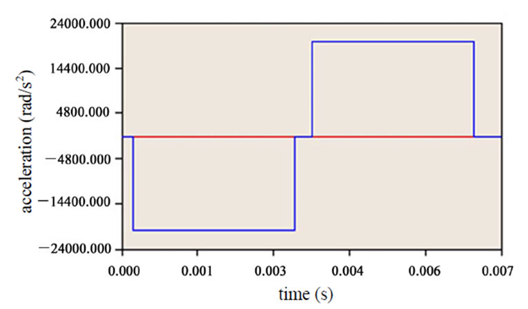
Figure 11. Acceleration profile as defined in TSS [acceleration (rad/s2) vs. time (s)].
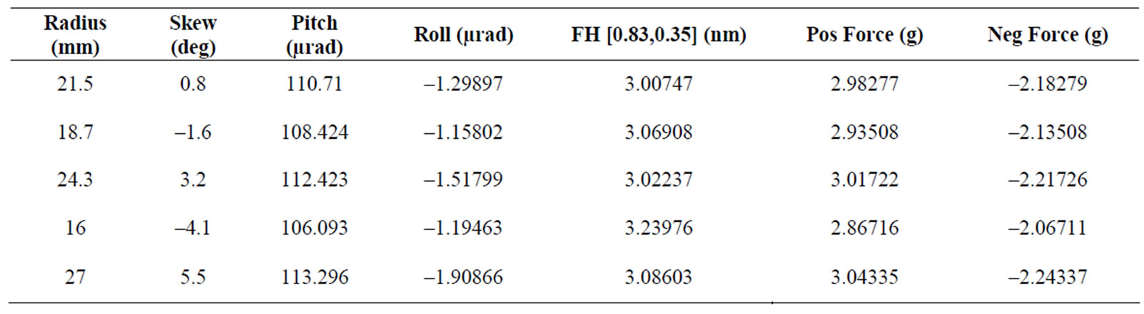
Table 8. Flying characteristics results of re-modified air bearing slider (“V-shape” double shallow steps).
 (a)
(a)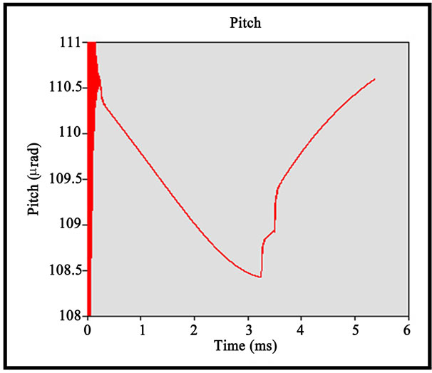 (b)
(b)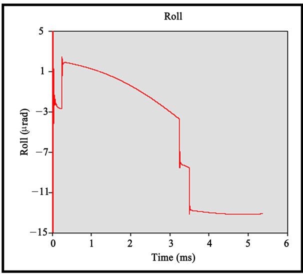 (c)
(c)
Figure 12. (a,b) TSS flying characteristic (displacement, pitch) against time (“V-Shape” double shallow steps); (c) TSS flying characteristic (roll) against time (“V-Shape” double shallow steps).
4 nm amplitude was defined. When the slider passes through this asperity, the slider will vibrate and then return to the stable stage within a certain period of time. The shorter the period, the better the slider performance is. The oscillations of flying characteristics decay in about 0.2ms as shown in Figure 13. Basically, the amplitude of the oscillations depends on the air bearing stiffness while the rate of decay of the oscillations de-
 (a)
(a)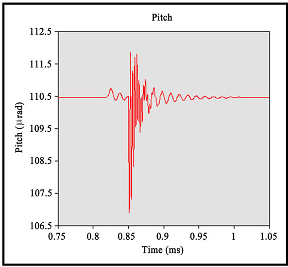 (b)
(b)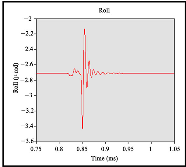 (c)
(c)
Figure 13. (a,b) RAS flying characteristic (displacement, pitch) against time (V-Shape); (c) RAS flying characteristic (roll) against time (V-Shape).
pends on the damping ratio of the sliders.
7. Design Optimization of Slider
The purpose of slider optimization is to seek for an optimal slider that is stable in its flying characteristics. The stability of flying height is of the most concern compared to pitch and roll, and as far as the flying height is concerned, the influential parameters are the size of trailing pad as well as the side rail. Therefore, optimization is done on the re-modified slider by specifying one constraint point and two constraints line (Figure 14). The point#10 of rail#2 (side rail) is allowed to moved in the x-direction as illustrated in Figure 15. This constraint point is meant to increase the side rail size and change the pitch value. An increase in size of side rail will affect the flying height performance, so the other two constraint lines, i.e. line translation and line extension, are defined on the trailing pad in order to trade off the effect of pitch and hence maintaining the original flying height. Line translation constraint is defined on rail#5, line with point#5 and point#6, which is allowed to move in x-direction, towards leading edge direction. Line extension constraint is also defined on the same line, but is only allowed to be shortened with a specified interval.
The results are obtained by executing the in-house developed code using MATLAB software. For the first result file, plotopt3.m (Figure 15) shows that there are 413 designs generated, 128 designs are ignored, with only 12 optimized designs. The objective function value dropped from 11, which is the initial cost, to the optimized cost, 5.561. The improvement is up to 49.44%. Second file, conrail3.m (Figure 16) shows the comparison between the original and the optimized designs. The point#10 of rail#2 has moved towards the leading edge and the line of the trailing pad has also shortened and adjusted towards the leading edge. The performances of the slider developed from the static and dynamic analysis
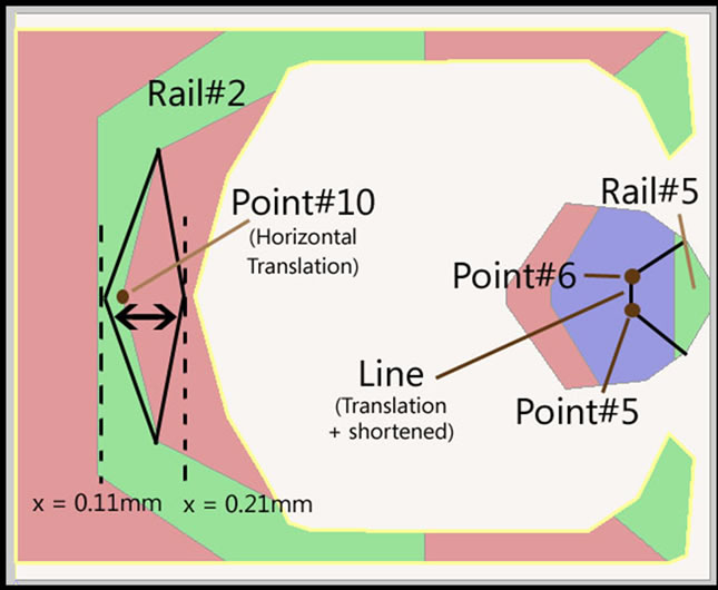
Figure 14. Constraints & possible optimized rails.
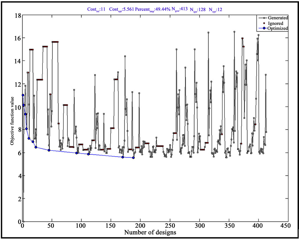
Figure 15. MATLAB post-process file plotopt3.m.
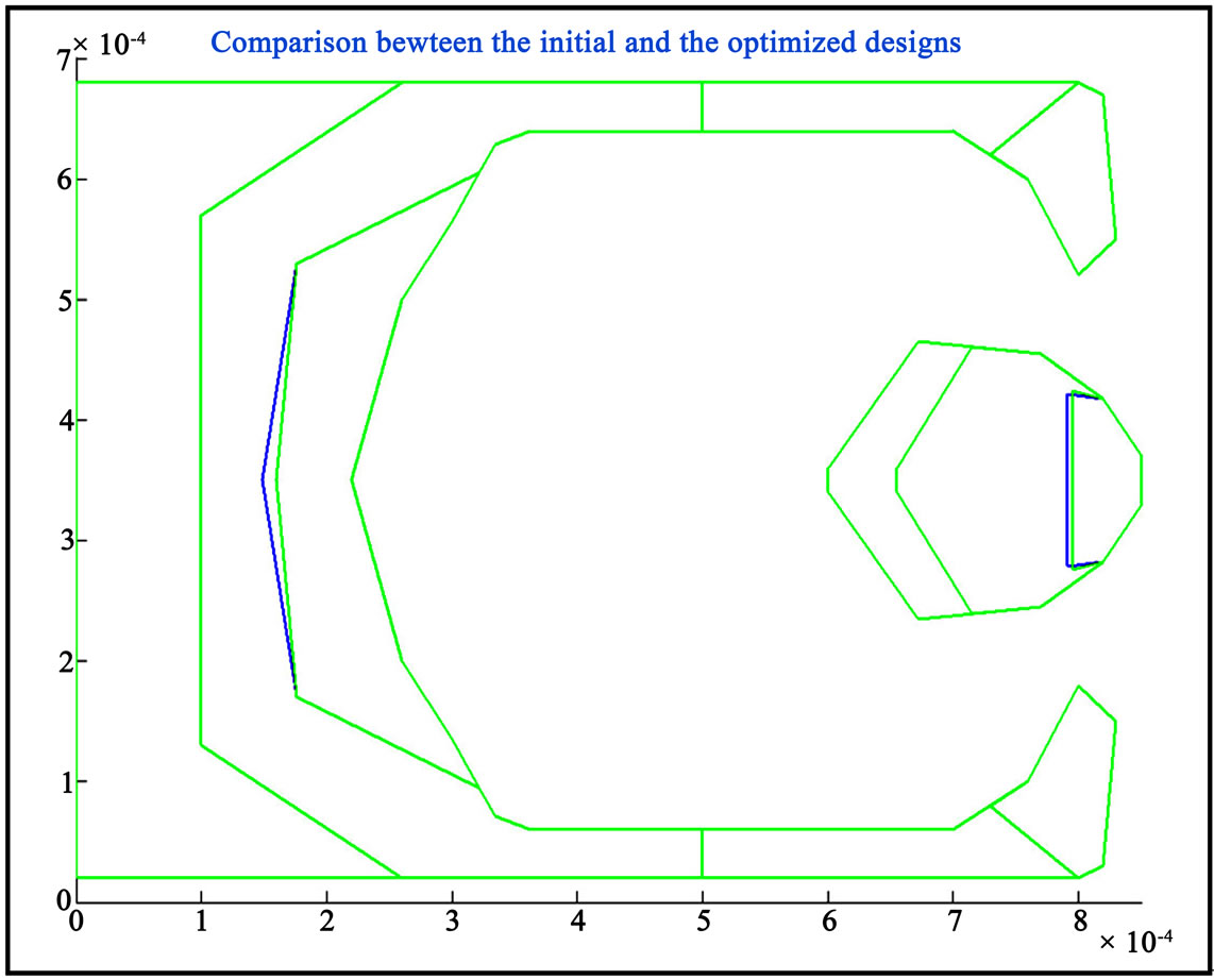
Figure 16. MATLAB post-process file conrail3.m (green: original; blue: optimized).
are rather close to the performances of the optimized design; therefore, it is reasonable that only slight modifications on rail are made. Third file, history3.m shows the flying characteristics results of the past 12 optimized sliders. It can be seen that the final optimized design has very low modulations in both flying height and pitch. The actual flying height variation has been reduced to about 0.20 nm; the pitch variation is about 5 µrad and the roll variation is about 0.9 µrad. The OD, MD, and ID in the legend are outer diameter, middle diameter, and inner diameter respectively. The fourth file, objterm3.m shows the variation of the objective function values of flying characteristics. The flying height term has an improvement of 57.2%. The final optimized design thus has a rather constant flying height profile around the targeted flying height. The roll term improves for 29.64%. The roll cutoff and pitch cutoff terms remain zero. Since the sensitivities of vertical, pitch, and roll are not studied and optimized at the moment, the stiffness matrix flag and the weight for the sensitivities terms are defined as zero, so the values of the rest of the objective terms equal to zero.
The optimized slider is finally being simulated in the dynamic simulator [14,15] to check for the dynamic performances. The results do not differ much when compared to the previous dynamic simulation results as there are only slight changes being made during the optimization process. Both dynamic simulation results agree to the design requirements so this optimized slider is considered as the final slider design as shown in Figure 17.
8. Conclusions
This paper focuses mainly on the development of a femto slider which meets today’s demanding requirements. In the investigation on the effect of parameters on flying characteristics, there is a transition of pitch value when the edges of two rails (of different recess heights) have a close x-distance, i.e. the air flow direction. For the effects
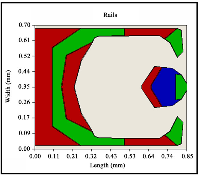
Figure 17. The final proposed femto air bearing slider.
of double shallow steps, the area and profiles are found to have certain controls on the air flow profile. By varying the air flow profile, low modulation of flying characteristics can be achieved. The Track Seeking Simulation results show that the variation of flying height and pitch are minimized to 0.24 nm and 2.3 µrad respectively. However, the roll variation (about 15 µrad) is relatively large. Therefore, the design of this initial slider can be adjusted to achieve a smaller roll variation. In the study on the responses to asperities, the flying characteristics of the proposed slider are able to return to the stable stage within 0.2 ms. The optimization effort shows that improvement on the stability of flying characteristics has been achieved when compared with the results of the pre-optimized slider. More optimal slider designs could be obtained by defining other constraints according to the design requirements.
9. REFERENCES
- B. Liu, M. Zhang, S. Yu, G., Leonard, Y. S., Hor and J. Xu, “Femto Slider Fabrication and Evaluation,” AsiaPacific Magnetic Recording Conference 2002 and IEEE Transactions on Magnetics, Vol. 39, No. 2, 2003, pp. 909-914.
- D. S. Chabra, S. A. Bolasna, L. K. Dorius and L. S. Samuelson, “Air Bearing Design Considerations for Constant Flying Height Applications,” IEEE Transactions on Magnetics, Vol. 30, No. 2, 1994, pp. 417-423.
- Y. Wada, T. Roppongi and I. Sato, “Flying Characteristics of Shallow Step Pads Slider for Low Flying,” IEEE Transactions on Magnetics, Vol. 35, No. 5, 1999, pp. 2475-2477.
- S. Lu, Y. Hu, M. O’Hara and D. B. Bogy, “Air Bearing Design, Optimization, Stability Analysis and Verification for Sub-25 nm Flying,” IEEE Transactions on Magnetics, Vol. 32, No. 1, 1996, pp. 103-108.
- J. K. Lee, J. Enguero, M. Smallen and A. Chao, “The Influence of Head Parameters on Take-off Velocity,” IEEE Transactions on Magnetics, Vol. 29, No. 6, 1993, pp. 3915-3917.
- B. H. Thornton, A. Nayak and D. B. Bogy, “Flying Height Modulation due to Disk Waviness of sub-5 nm Flying Height Air Bearing Sliders,” Journal of Tribology, Vol. 124, No. 4, 2002, pp. 762-770.
- J. Xu and B. Liu, “Flying Height Modulation and Femto Slider Design,” IEEE Transactions on Magnetics, Vol. 39, No. 5, 2003, pp. 2438-2440.
- Q.-H. Zeng and D. B. Bogy, “Slider Air Bearing Designs for Load/Unload,” IEEE Transactions on Magnetics, Vol. 35, No. 2, 1999, pp. 746-751.
- K. S. Park, J. I. Chun, Y. H. Lee, N. C. Park, H. S. Yang and Y. P. Park, “Improvement of Loading/Unloading Performance Using Control Input Position and Considering Disk Vibration Characteristics,” IEEE Transactions on Magnetics, Vol. 41, No. 2, 2005, pp. 819-824.
- T. G. Jeong and D. B. Bogy, “Measurements of SliderDisk Contacts during Dynamic Load-Unload,” IEEE Transactions on Magnetics, Vol. 27, No. 6, 1991, pp. 5073-5075.
- P. W. Smith and G. L. Best, “Figures of Merit for Dynamically Unloaded Air Bearing Sliders,” Tribology Transactions, Vol. 42, No. 2, 1999, pp. 407-412.
- H. Tanaka, H. Kohira and M. Matsumoto, “Effect of Air-Bearing Design on Slider Dynamics during Unloading Process,” IEEE Transactions on Magnetics, Vol. 37, No. 4, 2001, pp. 1818-1820.
- S. Weissner, F. Talke, H. Tokisue and J. Xu, “Experimental Comparison of Load/Unload Slider Dynamics for Two Different Pico-Slider Designs,” Tribology Transactions, Vol. 44, No. 4, 2001, pp. 699-703.
- Computer Mechanics Laboratory in the Mechanical Engineering, “CML Software,” University of California, Berkeley, 2008.
- Q.-H. Zeng and D. B. Bogy, “Effects of Certain Design Parameters on Load/Unload Performance,” IEEE Transactions on Magnetics, Vol. 36, No. 1, 2000, pp. 140-147.