Paper Menu >>
Journal Menu >>
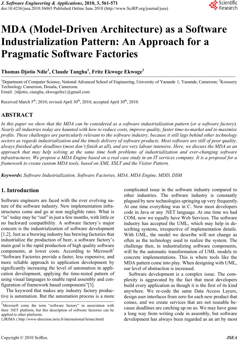 J. Software Engineering & Applications, 2010, 3, 561-571 doi:10.4236/jsea.2010.36065 Published Online June 2010 (http://www.SciRP.org/journal/jsea) Copyright © 2010 SciRes. JSEA MDA (Model-Driven Architecture) as a Software Industrialization Pattern: An Approach for a Pragmatic Software Factories Thomas Djotio Ndie1, Claude Tangha1, Fritz Ekwoge Ekwoge2 1Department of Computer Science, National Advanced School of Engineering, University of Yaounde 1, Yaounde, Cameroon; 2Koossery Technology Cameroon, Douala, Cameroon. Email: {tdjotio, ctangha, ekwogefee}@gmail.com Received March 5th, 2010; revised April 30th, 2010; accepted April 30th, 2010. ABSTRACT In this paper we show that the MDA can be considered as a software industrialization pattern (or a software factory). Nearly all industries today are haunted with how to reduce costs, improve quality, faster time-to-market and to maximize profits. These challenges are particularly relevant to the software industry, because it still lags behind other technology sectors as regards industrialization and the timely delivery of software products. Most software are still of poor quality, always finished after deadlines (most don’t finish at all), and are very labour intensive. Here, we discuss the MDA as an approach that may help solving at the same time both problems of industrialization and ever-changing software infrastructures. We propose a MDA Engine based on a real case study in an IT services company. It is a proposal for a framework to create custom MDA tools, based on XMI, XSLT and the Visitor Pattern. Keywords: Software Industrialization, Software Factories, MDA, MDA Engine, MDD, DSM 1. Introduction Software engineers are faced with the ever evolving na- ture of the software industry. New implementation infra- structures come and go at non negligible rates. What is “in” today may be “out” in just a few months, with little or no backward compatibility. A software factory’s major concern is the industrialization of software development [1,2]. Just as a brewing industry has brewing factories that industrialize the production of beer, a software factory’s main goal is the rapid production of high quality software components, at lower costs. According to Microsoft1 “Software Factories provide a faster, less expensive, and more reliable approach to application development by significantly increasing the level of automation in appli- cation development, applying the time-tested pattern of using visual languages to enable rapid assembly and con- figuration of framework based components”[3]. The keyword that makes any industry factory produc- tive is automation. But the automation process is a more complicated issue in the software industry compared to other industries. The software industry is constantly plagued by new technologies springing up very frequently. At one time everything was in C. Now most developers code in Java or any .NET language. At one time we had COM, now we equally have Web Services. The software industry has accepted the UML, which may help in de- scribing systems, irrespective of implementation details. With UML, the model we describe will not change as often as the technology used to realize the system. The challenge then, in industrializing software components, will be the automatic transformation of UML models to concrete implementations. This is where tools like the MDA pattern come into play. When designing with UML, our level of abstraction is increased. Software development is a complex issue. The com- plexity is aggravated by the fact that most developers build every application as though it is the first of its kind anywhere. We re-code the same Data Access Layers, design user interfaces from zero for each new product that comes, and we create services that are not reusable be- cause deadlines are catching up on us. We may have gone a long way from writing code in assembly, but software development has always been regarded as an art by most 1Microsoft coins the term “software factory” in association with their .NET platform, but this description of software factories can be applied to other platforms. LIRIMA ( http://www-direction.inria.fr/international/lirima.html) 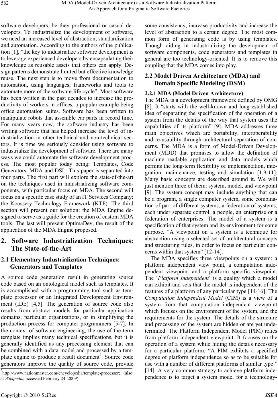 MDA (Model-Driven Architecture) as a Software Industrialization Pattern: 562 An Approach for a Pragmatic Software Factories software developers, be they professional or casual de- velopers. To industrialize the development of software, we need an increased level of abstraction, standardization and automation. According to the authors of the publica- tion [1], “the key to industrialize software development is to leverage experienced developers by encapsulating their knowledge as reusable assets that others can apply. De- sign patterns demonstrate limited but effective knowledge reuse. The next step is to move from documentation to automation, using languages, frameworks and tools to automate more of the software life cycle”. Most software has been written in the past decades to increase the pro- ductivity of workers in offices, a popular example being office automation suites. Software has been written to manipulate robots that assemble car parts in record time. For many years now, the software industry has been writing software that has helped increase the level of in- dustrialization in other technical and non-technical sec- tors. It is time we seriously consider using software to industrialize the development of software. There are many ways we could automate the software development proc- ess. The most popular today being: Templates, Code Generators, MDA and DSL. This paper is separated into four parts. The first part will explore the state-of-the-art on the techniques used in industrializing software com- ponents, with particular focus on MDA. The second will focus on a specific case study of an IT Services Company: the Koossery Technology Framework (KTF). The third section will present our solution: the MDA Engine de- signed to serve as a guide for the creation of custom MDA tools. The last will present OptimaDev, the result of the application of the MDA Engine proposed. 2. Software Industrialization Techniques: The State-of-the-Art 2.1 Elementary Industrialization Techniques: Generators and Templates A source code generation result in generating source code based on an ontological model such as templates. It is accomplished with a programming tool such as tem- plate processor or an Integrated Development Environ- ment (IDE) [4,5]. The generation of source code also results from abstract models for particular application domains, particular organizations, or in simplifying the production process for computer programmers [5-7]. In the context of software engineering, the use of the term template implies many technical specifications, but it is generally identified as any processing element that can be combined with a data model and processed by a tem- plate engine to produce a result document2. Source code generators improve the quality of source code, provide some consistency, increase productivity and increase the level of abstraction to a certain degree. The most com- mon form of generating code is by using templates. Though aiding in industrializing the development of software components, code generators and templates in general are too technology-oriented. It is to remove this coupling that the MDA comes into play. 2.2 Model Driven Architecture (MDA) and Domain Specific Modeling (DSM) 2.2.1 MDA (Model Driven Architecture) The MDA is a development framework defined by OMG [8]. It “starts with the well-known and long established idea of separating the specification of the operation of a system from the details of the way that system uses the capabilities of its platform” [9]. MDA addresses three main objectives which are portability, interoperability and re-usability through architectural separation of con- cerns. The MDA is a form of Model-Driven Develop- ment (MDD) that promises to allow the definition of machine readable application and data models which permits the long-term flexibility of implementation, inte- gration, maintenance, testing and simulation [1,9-11]. Many basic concepts are described around it. We will just mention three of them: system, model, and viewpoint [9]. The system concept may include anything that can be a program, a single computer system, some combina- tion of part of different systems, a federation of systems, each under separate control, a people, an enterprise or a federation of enterprises. The model of a system is a specification of that system and its environment for some purpose. “A viewpoint on a system is a technique for abstraction using a selected set of architectural concepts and structuring rules, in order to focus on particular con- cerns within that system” [12-14]. The MDA specifies three viewpoints on a system: a platform independent view point, a computation inde- pendent viewpoint and a platform specific viewpoint. The ‘Platform Independent’ is a quality which a model can exhibit and sets that the model is independent of the features of a platform of any particular type [14-16]. The Computation Independent Model (CIM) is a view of a system from that computation independent viewpoint which focuses on the environment of the system, and the requirements for the system. The details of the structure and processing of the system are hidden or are yet unde- termined. The Platform Independent Model (PIM) relies from platform independent viewpoint. It focuses on the operation of a system while hiding the details necessary for a particular platform. “A PIM exhibits a specified degree of platform independence so as to be suitable for use with a number of different platforms of similar type.” [14]. A very common strategy to achieve platform inde- pendence is to target a system model for a technology- 2http://www.nationmaster.com/encyclopedia/template-processor; (also at Wikipedia, accessed February 24, 2009) Copyright © 2010 SciRes JSEA 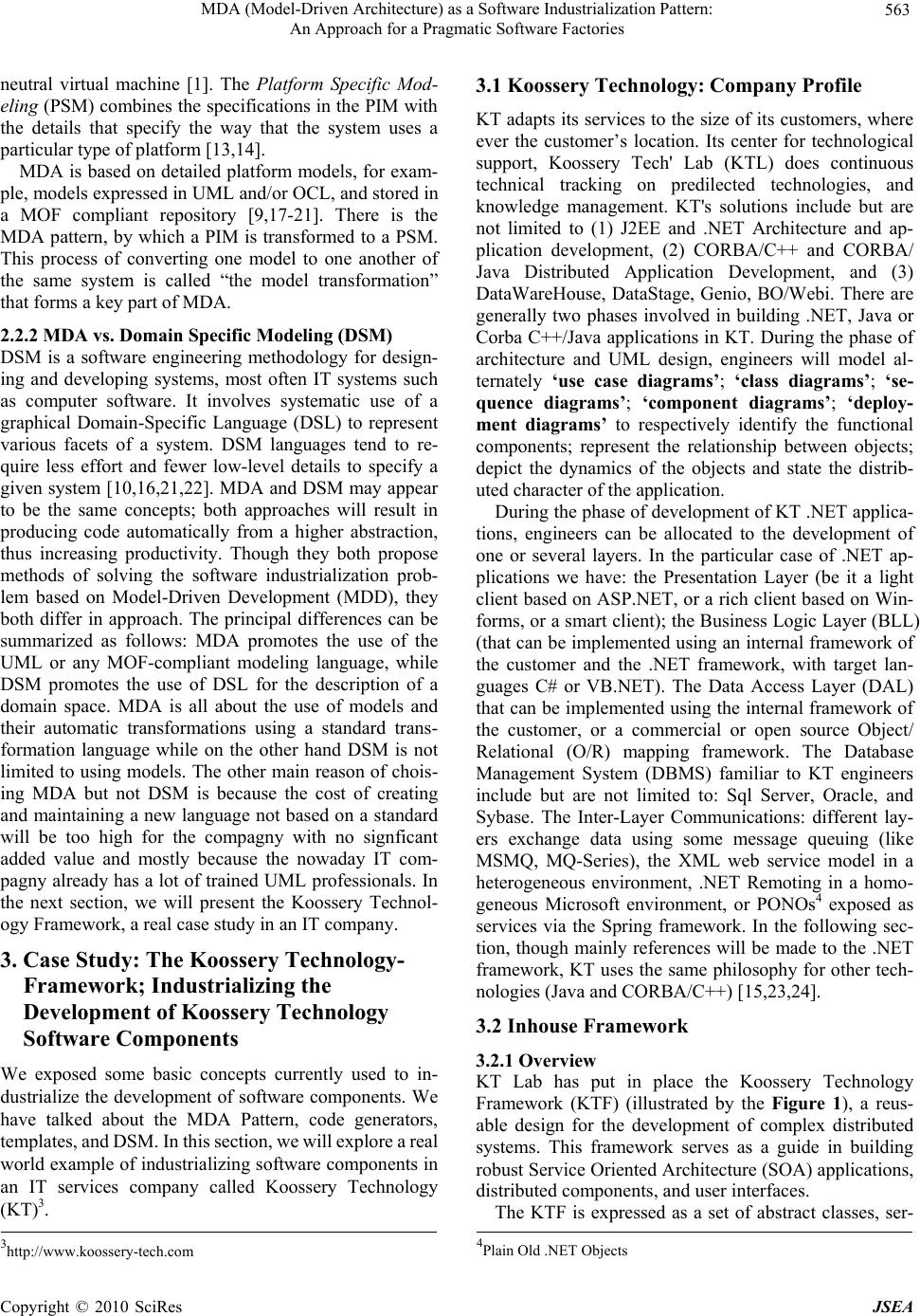 MDA (Model-Driven Architecture) as a Software Industrialization Pattern: 563 An Approach for a Pragmatic Software Factories neutral virtual machine [1]. The Platform Specific Mod- eling (PSM) combines the specifications in the PIM with the details that specify the way that the system uses a particular type of platform [13,14]. MDA is based on detailed platform models, for exam- ple, models expressed in UML and/or OCL, and stored in a MOF compliant repository [9,17-21]. There is the MDA pattern, by which a PIM is transformed to a PSM. This process of converting one model to one another of the same system is called “the model transformation” that forms a key part of MDA. 2.2.2 MDA vs. Domain Specific Modeling (DSM) DSM is a software engineering methodology for design- ing and developing systems, most often IT systems such as computer software. It involves systematic use of a graphical Domain-Specific Language (DSL) to represent various facets of a system. DSM languages tend to re- quire less effort and fewer low-level details to specify a given system [10,16,21,22]. MDA and DSM may appear to be the same concepts; both approaches will result in producing code automatically from a higher abstraction, thus increasing productivity. Though they both propose methods of solving the software industrialization prob- lem based on Model-Driven Development (MDD), they both differ in approach. The principal differences can be summarized as follows: MDA promotes the use of the UML or any MOF-compliant modeling language, while DSM promotes the use of DSL for the description of a domain space. MDA is all about the use of models and their automatic transformations using a standard trans- formation language while on the other hand DSM is not limited to using models. The other main reason of chois- ing MDA but not DSM is because the cost of creating and maintaining a new language not based on a standard will be too high for the compagny with no signficant added value and mostly because the nowaday IT com- pagny already has a lot of trained UML professionals. In the next section, we will present the Koossery Technol- ogy Framework, a real case study in an IT company. 3. Case Study: The Koossery Technology- Framework; Industrializing the Development of Koossery Technology Software Components We exposed some basic concepts currently used to in- dustrialize the development of software components. We have talked about the MDA Pattern, code generators, templates, and DSM. In this section, we will explore a real world example of industrializing software components in an IT services company called Koossery Technology (KT)3. 3.1 Koossery Technology: Company Profile KT adapts its services to the size of its customers, where ever the customer’s location. Its center for technological support, Koossery Tech' Lab (KTL) does continuous technical tracking on predilected technologies, and knowledge management. KT's solutions include but are not limited to (1) J2EE and .NET Architecture and ap- plication development, (2) CORBA/C++ and CORBA/ Java Distributed Application Development, and (3) DataWareHouse, DataStage, Genio, BO/Webi. There are generally two phases involved in building .NET, Java or Corba C++/Java applications in KT. During the phase of architecture and UML design, engineers will model al- ternately ‘use case diagrams’; ‘class diagrams’; ‘se- quence diagrams’; ‘component diagrams’; ‘deploy- ment diagrams’ to respectively identify the functional components; represent the relationship between objects; depict the dynamics of the objects and state the distrib- uted character of the application. During the phase of development of KT .NET applica- tions, engineers can be allocated to the development of one or several layers. In the particular case of .NET ap- plications we have: the Presentation Layer (be it a light client based on ASP.NET, or a rich client based on Win- forms, or a smart client); the Business Logic Layer (BLL) (that can be implemented using an internal framework of the customer and the .NET framework, with target lan- guages C# or VB.NET). The Data Access Layer (DAL) that can be implemented using the internal framework of the customer, or a commercial or open source Object/ Relational (O/R) mapping framework. The Database Management System (DBMS) familiar to KT engineers include but are not limited to: Sql Server, Oracle, and Sybase. The Inter-Layer Communications: different lay- ers exchange data using some message queuing (like MSMQ, MQ-Series), the XML web service model in a heterogeneous environment, .NET Remoting in a homo- geneous Microsoft environment, or PONOs4 exposed as services via the Spring framework. In the following sec- tion, though mainly references will be made to the .NET framework, KT uses the same philosophy for other tech- nologies (Java and CORBA/C++) [15,23,24]. 3.2 Inhouse Framework 3.2.1 Overview KT Lab has put in place the Koossery Technology Framework (KTF) (illustrated by the Figure 1), a reus- able design for the development of complex distributed systems. This framework serves as a guide in building robust Service Oriented Architecture (SOA) applications, distributed components, and user interfaces. The KTF is expressed as a set of abstract classes, ser- 4Plain Old .NET Objects 3http://www.koossery-tech.com Copyright © 2010 SciRes JSEA 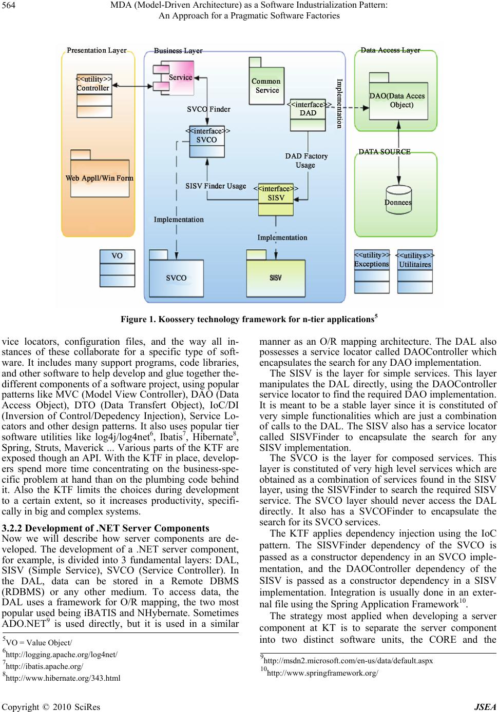 MDA (Model-Driven Architecture) as a Software Industrialization Pattern: An Approach for a Pragmatic Software Factories Copyright © 2010 SciRes JSEA 564 Figure 1. Koossery technology framework for n-tier applications5 vice locators, configuration files, and the way all in- stances of these collaborate for a specific type of soft- ware. It includes many support programs, code libraries, and other software to help develop and glue together the- different components of a software project, using popular patterns like MVC (Model View Controller), DAO (Data Access Object), DTO (Data Transfert Object), IoC/DI (Inversion of Control/Depedency Injection), Service Lo- cators and other design patterns. It also uses popular tier software utilities like log4j/log4net6, Ibatis7, Hibernate8, Spring, Struts, Maverick ... Various parts of the KTF are exposed though an API. With the KTF in place, develop- ers spend more time concentrating on the business-spe- cific problem at hand than on the plumbing code behind it. Also the KTF limits the choices during development to a certain extent, so it increases productivity, specifi- cally in big and complex systems. 3.2.2 Development of .NET Server Components Now we will describe how server components are de- veloped. The development of a .NET server component, for example, is divided into 3 fundamental layers: DAL, SISV (Simple Service), SVCO (Service Controller). In the DAL, data can be stored in a Remote DBMS (RDBMS) or any other medium. To access data, the DAL uses a framework for O/R mapping, the two most popular used being iBATIS and NHybernate. Sometimes ADO.NET9 is used directly, but it is used in a similar manner as an O/R mapping architecture. The DAL also possesses a service locator called DAOController which encapsulates the search for any DAO implementation. The SISV is the layer for simple services. This layer manipulates the DAL directly, using the DAOController service locator to find the required DAO implementation. It is meant to be a stable layer since it is constituted of very simple functionalities which are just a combination of calls to the DAL. The SISV also has a service locator called SISVFinder to encapsulate the search for any SISV implementation. The SVCO is the layer for composed services. This layer is constituted of very high level services which are obtained as a combination of services found in the SISV layer, using the SISVFinder to search the required SISV service. The SVCO layer should never access the DAL directly. It also has a SVCOFinder to encapsulate the search for its SVCO services. The KTF applies dependency injection using the IoC pattern. The SISVFinder dependency of the SVCO is passed as a constructor dependency in an SVCO imple- mentation, and the DAOController dependency of the SISV is passed as a constructor dependency in a SISV implementation. Integration is usually done in an exter- nal file using the Spring Application Framework10. The strategy most applied when developing a server component at KT is to separate the server component into two distinct software units, the CORE and the 5VO = Value Object/ 6http://logging.apache.org/log4net/ 9http://msdn2.microsoft.com/en-us/data/default.aspx 7http://ibatis.apache.org/ 10http://www.springframework.org/ 8http://www.hibernate.org/343.html  MDA (Model-Driven Architecture) as a Software Industrialization Pattern: 565 An Approach for a Pragmatic Software Factories BACKEND. The CORE includes all different interfaces, exceptions and Data Transfer Objects (DTOs). The BACKEND includes all concrete implementations of the CORE. The CORE is the heart of the server component. It contains the CORE_CONTRACT and the CORE_ BACKEND. CORE_CONTRACT includes all interfaces of the services offered by the server component to its clients. The CORE_BACKEND comprises all interfaces of the DAL and the SISV. The BACKEND contains the following packages: the DAO, SISV and SVCO. The DAO package contains all implementations of the DAL interfaces found in the CORE_BACKEND, the SISV package contains all implementations of the SISV inter- faces found in the CORE_BACKEND, the SVCO pack- age contains all implementations of SVCO interfaces found in the CORE_CONTRACT. The framework proposes a method of realizing the concrete implementations of the DAL, SISV and SVCO. The services of the server component may be exposed locally using assemblies, as web services using Spring, or by using .NET remoting using Spring. Logging is usu- ally accomplished via a logging framework e.g. Log4Net. All these layers are organized into separate Visual Studio projects that generate 6 principal artifacts: the CORE_ CONTRACT, CORE_BACKEND, SVCO, SISV and DAO assemblies plus a set of configuration files, as summarized in Figure 2. 3.3 The Need to Industrialize [1] KT, like most IT services companies, realized that with their actual methods close to handicraft, a lot of money was being lost when everything was done manually. The first approach to reduce the amount of craft was to capi- talize all of the company’s experience in a framework, the KTF; and organize methods for the realization of aproject. However, this first approach just permitted the engineers to have a working guide to the development of Figure 2. Koossery technology sample server component project structure [15] applications, with still a major part of the application done manually. There was thus a need for a second ap- proach that will reduce the amount of manual input, and which from the modeling phase generates an application respecting their standards [15,23,24]. We propose the MDA, amongst other software indus- trialization techniques, because it is the closest approach to really fulfilling this form of application generation. We expect the MDA approach from the UML model of an application, to generate all the application, all techni- cal services, all configuration files, all CRUD (Create, Read, Update and Delete) functionalities so that the de- veloper in the end will only have to complete with spe- cific algorithms for only the most complicated business logic. 3.4 Preparations for the MDA: Identification of PIM, PSM and CM in KTF To apply the MDA pattern to the KTF, let us identify what we will use as PIM, PSM and CM. Let us also de- fine how our models will be marked, so as to perform automatic transformations from a higher level of abstrac- tion (the PIM) to a lower level of abstraction (the CM). The choice of PIM has been natural: UML. Various enterprise UML tools are already used in KT in- cluding Rational Rose from IBM, Poseidon for UML from GentleWare and Enterprise Architect from Sparx Systems. The choice of PSMs has been limited to the various technologies used in KT at the present moment. Webservices or .NET remoting for exposing ser- vices, Hybernate or iBATIS for O/R mapping, Spring for Dependency Injection and exposure of PONOs and POJOs11 as services, Log4J/Log4Net for logging etc. The CM can either be in Java, C# or CORBA/C++ for source code, and XML for configuration files. Now that we have identified the various models, we have to perform automatic transformations from the ab- stract models to the code models. The strategy we have used to aid in this automatic transformation is by using marks, and the possible use of OCL to produce models of higher quality. So how could we mark UML diagrams for the KTF? There are some standards respected in all modeling done in KT. All DAO, SISV, and SVCO interfaces are prefixed with “I” and suffixed with DAO, SISV and SVCO respectively e.g. IUserDAO, IUserSISV and IUs- erSVCO. All DAO, SISV and SVCO concrete imple- mentations are suffixed with DAOImpl, SISVImpl and SVCOImpl respectively e.g. UserDAOImpl, User-SIS- VImpl, and UserSVCOImpl. All DTOs are suffixed with 11Plain Old Java Objects Copyright © 2010 SciRes JSEA  MDA (Model-Driven Architecture) as a Software Industrialization Pattern: 566 An Approach for a Pragmatic Software Factories DTO, e.g., UserDTO and all relational database tables are stereotyped with entity. With this level of detail in the UML models, a choice was made to use UML classifier suffixes as a means of marking our models. These marks help us perform the automatic transformations from PIM (the UML model) to CM (the resultant code). e.g. a classifier that inherits from no other classifier and marked with the DAOImpl suffix in the PIM will, in the resultant CM (C# or Java code), inherits from the AbstractDataAccessObject ab- stract class defined in the KTF. Another method of marking will be the use of stereotypes; e.g. classifiers marked with the entity stereotype will be transformed into Data Definition Language (DDL) statements in Structured Query Language (SQL). Finally, we use the OCL to add some elements of business logic to the mod- els, like saying “an employee’s age must be between 18 and 65”. Now that we have identified the PIM, PSM and CM in the KTF and stipulated how the models will be marked, the framework is ready for MDA Transformations. The next step is using an MDA tool that performs the auto- matic transformations between models. 4. Designing a Lightweight MDA Engine 4.1 Motivation So we have the problem of applying the MDA pattern in a company. Creating some custom software that will perform specific and not general automatic transforma- tions from PIM to CMs will be more beneficial to the company on one hand, but may cost the company more time and money developing such software on the other hand. The custom software can be tuned to extract maximum benefit from the MDA pattern. It is to help create custom MDA tools that the idea of designing a lightweight MDA Engine sprung up. This MDA Engine will serve as a guide for the creation of custom MDA tools, which can be tuned for the specific enterprise, con- sistent, and uses as much as possible standard file for- mats, thus increasing the Return On Investment (ROI) for the creation of the custom MDA tool. It was designed to be lightweight so that the custom MDA tool developer will be able to start his/her project very rapidly. 4.2 Custom MDA Tool 4.2.1 Pragmatic Approach To be pragmatic, we cannot possibly model every aspect of the business logic in UML. Maybe with the arrival of Executable UML this will be possible. But why should everything be modeled in UML? An argument in favor of modeling everything in UML is the ability to generate full working application only from the UML model. Ar- guments against relate the complexity and heaviness of these models. A pragmatic approach will involve some hybrid of UML and a 3GL. When computers were in- vented, everyone thought that paper usage in offices would reduce. Just the opposite is complete taking place today, with computers printing out more and more paper every day. Likewise, will the MDA eliminate the need for programmers? Not necessarily. With present and near future technology, some parts of a software application will always require low-level coding. It just doesn’t have to be a lot of very low-level coding. It is only by creating custom software that we can respect these criteria for each particular enterprise. The main reason why software developers sometimes react very critical on MDA is that MDA automates the heart of their profession. The generated code is not sim- ply like how they code. This has prompted the develop- ment of a lightweight MDA Engine, from which devel- opers can produce generated code from abstract models, their way. 4.2.2 The Broad View The mere fact that we are trying to automatically trans- form a visual language like UML to some code may sound like a daunting task. Do we have to write Com- puter-aided design (CAD)-like software that understands shapes? That would be a very difficult thing to do. What would help is if we had an electronic format that repre- sents these visual models, and permit us to access parts of these models. There exists such an electronic format: the XMI (ML Metadata Interchange) format. XMI: Now that our visual models can be transformed to electronic formats, we have to be able to perform MDA transformations on these models. Is there any standard for the transformation of XMI files? The QVT12 exists, but does not suit our case since it cannot generate source code and no concrete implementation exists at the time of writing. So there is yet no implemented standard for transforming XMI files to any other type, but the problem can be solved indirectly. Since XMI files are XML files, we can address the problem by looking for a standard for transforming XML files. Fortunately, the XML format already has a standard for transformations from XML to any desired format, the XSLT (Extensible Stylesheet Language Transformations). Since XMI is an XML file, we can thus define a mapping between MDA transformations and XSL Transformations. ESLT: So to conclude, the proposed approach is sim- ply to export UML models (our PIM) to the XMI format, then perform XSLT transformations to obtain specific code, configuration files or other text files(the CM). No need to depend on a proprietary format, or tool. Now that we have a view of how transformations will 12http://smartqvt.elibel.tm.fr/, http://en.wikipedia.org/wiki/QVT; http://umtqvt.sourceforge.net/; http://www.omg.org/docs/ptc/07-07-07.pdf (accessed 24/103/2009). Copyright © 2010 SciRes JSEA  MDA (Model-Driven Architecture) as a Software Industrialization Pattern: An Approach for a Pragmatic Software Factories Copyright © 2010 SciRes JSEA 567 be performed, we can build an MDA Engine that will help us do these transformations. 4.2.3 Architecture of the Lightweight MDA Engine Since we have an XMI document that has to be trans- formed to various code models, it seemed natural to use the Visitor Design Pattern, where each visitor will visit the XMI document containing our UML model and gen- erate corresponding code. We may have a visitor for the generation of each specific interface, configuration file, concrete class implementation or even other XMI files. Sometimes the order in which the visitors visit is impor- tant. The MDA Engine has to take care of that. The main concepts are illustrated by the Figure 3. The Figure 4 shown below illustrates the UML Class Figure 3. MDA engine main concepts Figure 4. MDA engine  MDA (Model-Driven Architecture) as a Software Industrialization Pattern: 568 An Approach for a Pragmatic Software Factories Diagram of the MDA Engine. The participants of the UML Class Diagram are: IGeneratable: Interface that represents any generat- able document. All generatable documents accept a visitor. In this particular case, all generatable docu- ments accept an IXMIVisitor. IXmiVisitor: Interface that represents a visitor for an XMI document. Every visitor has a name. The visitor’s operation is defined in the visit method. IXmiTransformationEngine: Interface that defines a common contract for all XSLT processors. There are two methods. One that transforms an XMI document to a text document, and another that spe- cifically transforms an XMI document to another XML document. SimpleXmiTransformationEngine: A concrete XS- LT processor that implements IXmiTransforma- tionEngine. MDATransformationInfo: A data structure that holds a list of visitors for a particular generatable document. MDACoreEngine: This contains a list of MDAT- ransformationInfos. It has a Generate method that calls each visitor sequentially as defined in each MDATransformationInfo object. XmiDocument: Data structure that represents a “generatable” XMI document. It has two properties that expose the DOM representation of the XMI file. One that is editable XmlDoc, and another that is not editable (but faster) XPathDoc. As soon as an XmiDocument accepts an IXmiVisitor, it calls this visitor’s visit method on itself. AbstractXmiDocumentVisitor: All visitors can de- rive from this base class to facilitate their work. It has a reference to an IXmiTransformerEngine for XSLT processing, a dictionary of namespaces used in the XSLT files, a dictionary of Parameters that can be passed to the XSLT processor. It also has a utility function that maps an XMI ID to a classifier name called mapXmiToClassifier. Each visitor may use the XSLT processor for MDA Transformations. The AbstractXmiDocumentVisitor may also pos- sess a log object based on a logging framework like log4J/log4Net for logging purposes. ConcreteVisitor1 and ConcreteVisitor2: These are concrete transformations to be performed in the IXmiDocument. Each operation is defined in the concrete class’s visit method This engine is distributed as a third party library, in the form of a .NET assembly or Java jar file. All the devel- oper has to do now is to write visitors based on the Ab- stractXmiDocumentVisitor, and define a set of XSLT templates. The MDACoreEngine is then filled with a list of MDATransformationInfo objects, which in turn are filled with visitors either programmatically or using de- pendency injection (one may use the Spring IoC Frame- work for depency injection). To perform transformations, simply call the Generate() method of the MDACoreEn- gine object. The next section presents Optimadev, an application usage/case of the MDA Engine. 5. OptimaDev: A Prototype for MDA Engine Creating a prototype for the MDA Engine will consist of creating an incomplete model of the future full-featured MDA Engine, which can be used to let the users have a first idea of the completed program. This prototype is called OptimaDev. 5.1 Preliminary Specification The preliminary specification for OptimaDev was to cre- ate, automatically from the UML model, a set of artifacts. These included, but are not limited to artifacts needed for the CORE_CONTRACT, CORE_BACKEND, DAO, SISV and SVCO components. Some of the artifacts to be generated are displayed in Figure 5 below. 5.2 Analysis In order to fulfill the preliminary specifications, Optima- Dev was designed as a custom MDA Engine that will perform MDA transformations for us, creating artifacts that respect the KTF. The choice of a custom MDA tool was taken because of the incapability of current MDA tools [13] in generating artifacts that respect the KTF. Based on the architecture in Subsection 5.1 and illustrate by the Figure 5, we created 9 visitors. All visitors inherit from the AbstractXMIDocumentVisitor base class as found in 4.2.3, and are listed in Table 1. OptimaDev was also furnished with a Graphical User Interface to ease the transformation process (see Figure 6). Figure 5. OptimaDev: Preliminary specifications Copyright © 2010 SciRes JSEA  MDA (Model-Driven Architecture) as a Software Industrialization Pattern: 569 An Approach for a Pragmatic Software Factories 5.3 Implementing the Prototype The user interface permits the user to input his XMI file representing his model, and choose an output directory where OptimaDev will serialize results. The XMI file is obtained by exporting from a UML design tool. After generation, OptimaDev provides visual feedback on the status of the generation, like the number of files success- fully generated. As shown in Figure 6, OptimaDev is cautious enough to detect if there was an error during transformations, and robust enough to continue func- tioning after having signaled the error. Finally, the gen- erated artifacts are serialized in directory structures that closely resemble what is expected in a KT project. 5.4 Case Study or Application of OptimaDev: SoNetSec 5.4.1 Context SoNetSec is a Real Estate Servicing company located in Cameroon. To ameliorate its services, SoNetSec has de- cided to have at its disposal an Information System in the form of a family of software that will guarantee at the same time its agility and its global competivity. Without entering into the details of the functional specifications, we will briefly list some of its non functional specifications: The principal application, which will serve to show- cast, promote and ecommerce its products and ser- vices will be a transactional web based Internet ap- plication, capable of supporting high visiting rates. Some applications may have to be implemented using rich clients. The application will be conceived and implemented as a set of autonomous services. Scalability, security, robustness, response time, ma- intenance issues have to be considered in the concep- tion and implementation of the different applications. Fortunately enough, the KTF already facilitates the creation of software applications and software compo- nents with such non functional specifications. Some por- tions of the Information System to be realized were given to two software engineers and a senior software architect. What is interesting to recall is that within KT, most en- gineers communicate via UML models. In the course of prototyping, a study of how the engi- neers and the senior architect modeled the Information System was done, including a study of how these models were implemented. It was the job of the prototype MDA Engine, OptimaDev, to automatically produce source code respecting the KTF from these visual representa- tions. The feedback of the engineers, obtained through agile methods, was indispensable in perfecting the 9 visitors listed in Table 1 below. This helped create source code and configuration files that were to be com- pared with what was done manually. 5.4.2 Preliminary Results and Benefits The autogenerated code improves on quality, consistency, productivity and abstraction compared to manual code Figure 6. OptimaDev: Automatic error detection Copyright © 2010 SciRes JSEA  MDA (Model-Driven Architecture) as a Software Industrialization Pattern: 570 An Approach for a Pragmatic Software Factories Table 1. Visitors for the OptimaDev (MDA transformation visitors used in the OptimaDev) Visitor Description 1 DTOVisitor From the PIM, it extracts all DTOs from class diagrams and serializes each DTO in a separate file in the choice programming language. This visitor is meant to generate 100% of the code. 2 DAOImplVisitor From the PIM, it extracts all DAO Implementations from class diagrams and serializes each implementation in a separate file in the choice programming language. This visitor is meant to gen- erate stubs for the implementations with support of very common CRUD method signatures. This accounts for 95% of the code. 3 DAOInterfaces- Visitor From the PIM, it extracts all DAO Interfaces from class diagrams and serializes each implementation in a se- parate file in the choice programming language. This visitor is meant to gen- erate 100% of the code. 4 SISVImplVisitor From the PIM, it extracts all SISV Implementations from class diagrams and serializes each implementation in a separate file in the choice programming language. This visitor is meant to gen- erate stubs, accounting for 75% of code. 5 SISVInterfaces- Visitor Same as DAOInterfacesVisitor, but for SISV interfaces. This visitor is meant to generate 100% of the code. 6 SVCOImplVisitor Same as SISVImplVisitor, but for SVCO implementations. This visitor is meant to generate 75% of the code. 7 SVCOInterfaces- Visitor Same as DAOInterfacesVisitor, but for SVCO interfaces. This visitor is meant to generate 100% of the code. 8 SpringVisitors From the PIM, it extracts all DAO, SISV and SVCO Implementations from class diagrams and setups spring con- figuration files for Inversion of Control. It also sets up the service locators of each of these layers. This visitor is meant to generate 100% of the code. 9 IbatisRequestsVisi- tor From the PIM, it extracts all DAO and DTO Implementations from class dia- grams and creates iBatis request con- figuration files which are each serial- ized in a separate file in the choice programming language. This visitor is meant to generate stubs for the imple- mentations with support of very com- mon CRUD method signatures. This accounts for 95% of the code. 6. Conclusions and Perspectives approaches which simply provides flexibility and control. Equally, Knowledge Base was a great benefit. The proc- ess of adopting the MDA pattern has forced the extrac- tion of the best of individual KT experts into the MDA Engine, OptimaDev. The approach we adopted helps us create pragmatic software factories that boost the industrialization of software development. We have particularly emphasized on the MDA pattern as a form of MDD and as a software factory. The best approach will be to create some custom tool that adapts the MDA pattern for each company. The MDA Engine is a proposal for a framework to create custom MDA tools, based on XMI, XSLT and the Visitor Pattern. It serves as a starter kit to help develop MDA tools that are tuned to a company’s business logic, or software development strategies. We have also described the use of this MDA Engine to build a prototype custom MDA tool (internal code name: OptimaDev) for Koossery Technology (KT). For Opti- maDev, the KT MDA tool prototype, we realized some visitors based on the MDA Engine proposed. These visi- tors are designed to generate code for the development of a server side component following the KT Framework. Together with the addition of other visitors for the pres- entation layer, the support of the Object Constraint Lan- guage (OCL) especially for visitors targeting the business layer, we are very confident that with time the custom MDA tool’s roadmap will be from code generator, to software component generator, and finally to a complete software application generator. For the perspective point of view, there are many things we can add to this basic MDA Engine. Let’s men- tion some here. Multi Agent System (MAS), where we will have intelligent agents instead of visitors that perform transformations. Expert System (ES), where the MDA Engine may instead be conceived as an inference engine with a set of inference rules that transform models. This permits the transformation process to be more de- clarative than imperative (see [7]). OCL Support, to be able to produce models of even higher quality. xUML or Executable UML support, to describe the dynamics of a domain [20]. Round-trip engineering, to synchronize changes between model and code. AI/Fuzzy Logic: because the model itself can have some errors which some Artificial Intelligence or Fuzzy Logic can help. And others e.g. Velocity template language support, because it closely resembles the output code, unlike Copyright © 2010 SciRes JSEA  MDA (Model-Driven Architecture) as a Software Industrialization Pattern: 571 An Approach for a Pragmatic Software Factories XSLT. 7. Acknowledgements Special thanks go to Professor Jean Claude Derniame of Institut Polytechnique de Loraine at Nancy France, to have reviewed this paper, and also to Koossery Tech- nology Cameroon to have provided us with a real test environment. REFERENCES [1] J. Greenfield and K. Short, “Moving to Software Factories.” http://www.softwarefactories.com/ScreenShots/MS-WP-0 4.pdf [2] DoFactory.com, “Design Patterns in C#, VB.NET WPF, WCF, LINQ, PATTERNS,” Data & Object Factory™, http://www.dofactory.com/Patterns/Patterns.aspx [3] Microsoft, “Domain-Specigic Language Tools.” http://msdn2.microsoft.com/en-us/vstudio/aa718368.aspx [4] P. V. Hoof, “Code-Gen–about and technical documentation.” http://forgeftp.novell.com//codegen/docs/Technical%20do cumentation/codegen_doc.pdf [5] AndroMDA, “Extensible Code Generator.” http://www. andromda.org [6] Code Generation Network, “Code Generation Network.” http://www.codegeneration.net/tiki-index.php? page=Mod elsIntroduction [7] ExpertCoder, “Code Generation Libraries for .NET, Mono and dotGNU.” http://expertcoder.sourceforge.net/en/index.html [8] A. Kleppe, J. Warmer and W. Bast, “MDA Explained: The Practice and Promise of the Model Driven Architecture.” Addison Wesley, Massachusetts, 2003. [9] J. Miller and J. Mukerji, “MDA Guide Version 1.0.1.” http://www.omg.org/docs/omg/03-06-01.pdf [10] A. Kleppe, J. Warmer and W. Bast, “MDA Explained: The Model-Driven Architecture: Practice and Promise,” Addison Wesley Professional, Massachusetts. [11] J. S. Mellor, S. Kendall, A. Uhl and D. Weise, “MDA Distilled: Principles of Model-Driven Architecture.” Addison Wesley Professional, Massachusetts, 2003. [12] S. Sewall, “Executive Justification for Adopting Model Driven Architecture (MDA).” http://www.omg.org/mda/mdafiles/11-03_Sewall_MDA_p aper.pdf [13] Equipe SoftFluent, “Livre Blanc CodeFluent L’approche de Génie Logiciel de SoftFluent.” http://www.softfluent.com/codefluent_home_en.aspx [14] “What is MDA?” http://www.modelbased.net/mdi/mda/ mda. html [15] E. E. Fritz, “Pragmatic Software Factories: Industrializa- tion of the Development of Software,” Masters of Thesis of the National Advanced School of Engineering, Univer- sity of Yaounde 1, 2007. [16] J. M. Embe, “MDA: Applications de la Trans- formation des Modèles à la Génération d’Applications Trois Tiers,” Ecole Nationale Supérieure Polytechnique, Université de Yaoundé 1, 2005. [17] D. Pilone and N. Pitman, “UML 2.0 in a Nutshell,” O’Reilly, 2005. [18] S. Mellor and M. Balcer, “Executable UML: A Foundation for Model-Driven Architecture,” Addison Wesley Pro- ssional, 2002. [19] J. Warmer and A. Kleppe, “Object Constraint Language, Getting Your Models Ready for MDA,” Addison Wesley Professional, Massachusetts, 2003. [20] 20nUML. http://numl.sourceforge.net/index.php/MainPage [21] openArchitectureWare.organization, “Official Open Archi- tectureWare.” http://www. openarchitectureware.org [22] S. Cook, J. Gareth, S. Kent and A. Cameron, “Domain- Specific Development with Visual Studio DSL Tools,” Addison Wesley Professional, Massachusetts, 2007. [23] M. Yacoubou, “Développement Industrialisé d'Appli- cations n-tiers: Partie FrontEnd,” Master’s Thesis of the National Advanced School of Engineering, University of Yaounde 1, 2007. [24] P. Djomga, “Développement Industrialisé d'Applications n-tiers: Partie BackEnd,” Master’s Thesis of the National Advanced School of Engineering, University of Yaounde 1, 2007. Copyright © 2010 SciRes JSEA |