Paper Menu >>
Journal Menu >>
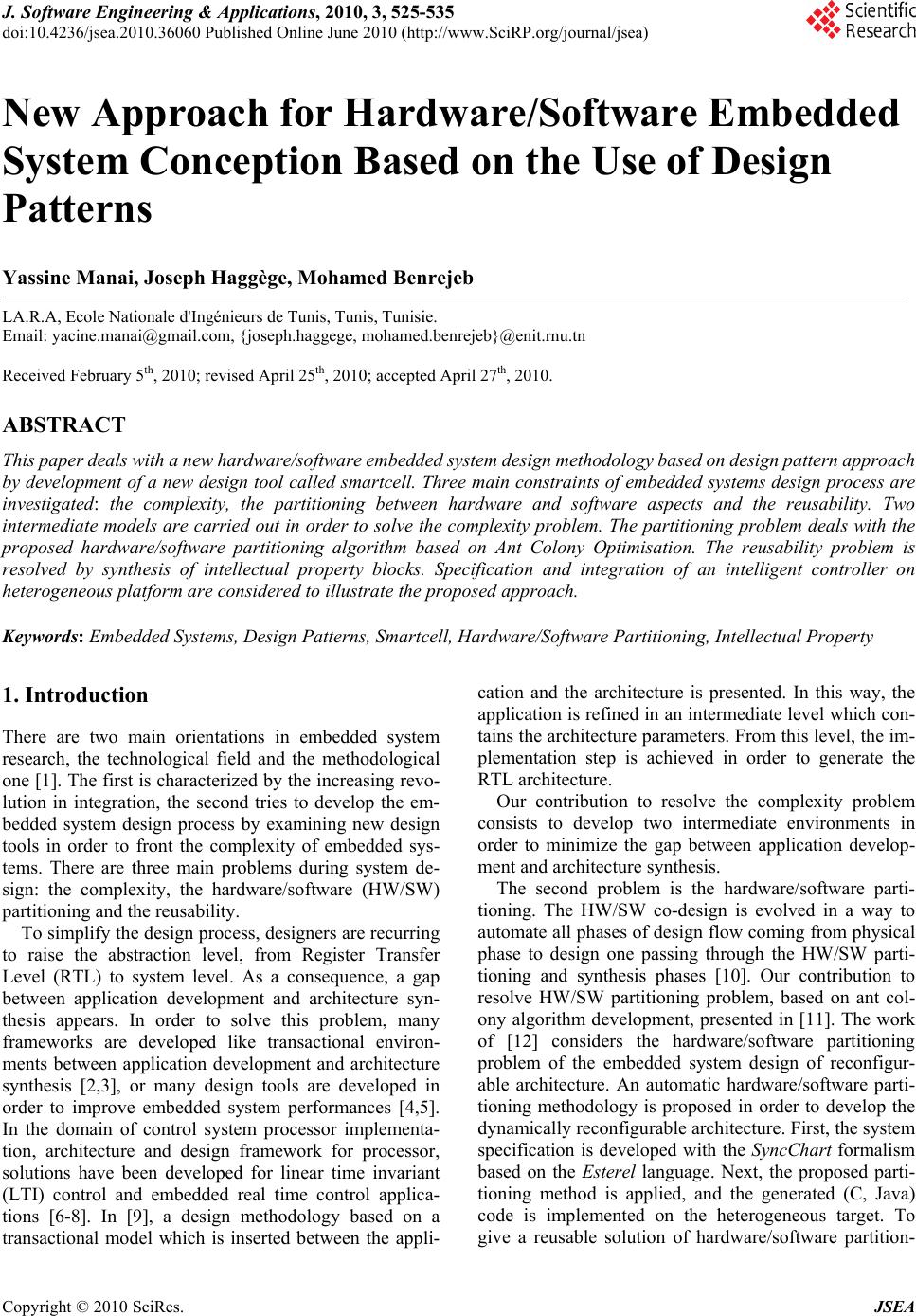 J. Software Engineering & Applications, 2010, 3, 525-535 doi:10.4236/jsea.2010.36060 Published Online June 2010 (http://www.SciRP.org/journal/jsea) Copyright © 2010 SciRes. JSEA New Approach for Hardware/Software Embedded System Conception Based on the Use of Design Patterns Yassine Manai, Joseph Haggège, Mohamed Benrejeb LA.R.A, Ecole Nationale d'Ingénieurs de Tunis, Tunis, Tunisie. Email: yacine.manai@gmail.com, {joseph.haggege, mohamed.benrejeb}@enit.rnu.tn Received February 5th, 2010; revised April 25th, 2010; accepted April 27th, 2010. ABSTRACT This paper deals with a new hardware/software embedded system design methodology based on design pattern approach by development of a new design tool called smartcell. Three main constraints of embedded systems design process are investigated: the complexity, the partitioning between hardware and software aspects and the reusability. Two intermediate models are carried out in order to solve the complexity problem. The partitioning problem deals with the proposed hardware/software partitioning algorithm based on Ant Colony Optimisation. The reusability problem is resolved by synthesis of intellectual property blocks. Specification and integration of an intelligent controller on heterogeneous platform are considered to illustrate the proposed approach. Keywords: Embedded Systems, Design Patterns, Smartcell, Hardware/Software Partitioning, Intellectual Property 1. Introduction There are two main orientations in embedded system research, the technological field and the methodological one [1]. The first is characterized by the increasing revo- lution in integration, the second tries to develop the em- bedded system design process by examining new design tools in order to front the complexity of embedded sys- tems. There are three main problems during system de- sign: the complexity, the hardware/software (HW/SW) partitioning and the reusability. To simplify the design process, designers are recurring to raise the abstraction level, from Register Transfer Level (RTL) to system level. As a consequence, a gap between application development and architecture syn- thesis appears. In order to solve this problem, many frameworks are developed like transactional environ- ments between application development and architecture synthesis [2,3], or many design tools are developed in order to improve embedded system performances [4,5]. In the domain of control system processor implementa- tion, architecture and design framework for processor, solutions have been developed for linear time invariant (LTI) control and embedded real time control applica- tions [6-8]. In [9], a design methodology based on a transactional model which is inserted between the appli- cation and the architecture is presented. In this way, the application is refined in an intermediate level which con- tains the architecture parameters. From this level, the im- plementation step is achieved in order to generate the RTL architecture. Our contribution to resolve the complexity problem consists to develop two intermediate environments in order to minimize the gap between application develop- ment and architecture synthesis. The second problem is the hardware/software parti- tioning. The HW/SW co-design is evolved in a way to automate all phases of design flow coming from physical phase to design one passing through the HW/SW parti- tioning and synthesis phases [10]. Our contribution to resolve HW/SW partitioning problem, based on ant col- ony algorithm development, presented in [11]. The work of [12] considers the hardware/software partitioning problem of the embedded system design of reconfigur- able architecture. An automatic hardware/software parti- tioning methodology is proposed in order to develop the dynamically reconfigurable architecture. First, the system specification is developed with the SyncChart formalism based on the Esterel language. Next, the proposed parti- tioning method is applied, and the generated (C, Java) code is implemented on the heterogeneous target. To give a reusable solution of hardware/software partition- 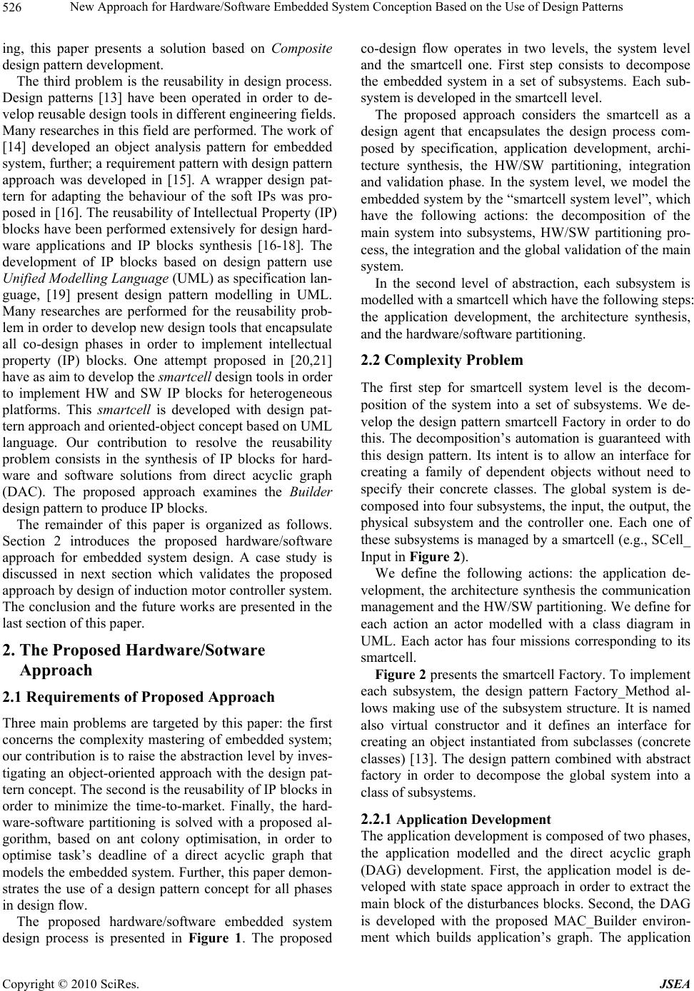 New Approach for Hardware/Software Embedded System Conception Based on the Use of Design Patterns 526 ing, this paper presents a solution based on Composite design pattern development. The third problem is the reusability in design process. Design patterns [13] have been operated in order to de- velop reusable design tools in different engineering fields. Many researches in this field are performed. The work of [14] developed an object analysis pattern for embedded system, further; a requirement pattern with design pattern approach was developed in [15]. A wrapper design pat- tern for adapting the behaviour of the soft IPs was pro- posed in [16]. The reusability of Intellectual Property (IP) blocks have been performed extensively for design hard- ware applications and IP blocks synthesis [16-18]. The development of IP blocks based on design pattern use Unified Modelling Language (UML) as specification lan- guage, [19] present design pattern modelling in UML. Many researches are performed for the reusability prob- lem in order to develop new design tools that encapsulate all co-design phases in order to implement intellectual property (IP) blocks. One attempt proposed in [20,21] have as aim to develop the smartcell design tools in order to implement HW and SW IP blocks for heterogeneous platforms. This smartcell is developed with design pat- tern approach and oriented-object concept based on UML language. Our contribution to resolve the reusability problem consists in the synthesis of IP blocks for hard- ware and software solutions from direct acyclic graph (DAC). The proposed approach examines the Builder design pattern to produce IP blocks. The remainder of this paper is organized as follows. Section 2 introduces the proposed hardware/software approach for embedded system design. A case study is discussed in next section which validates the proposed approach by design of induction motor controller system. The conclusion and the future works are presented in the last section of this paper. 2. The Proposed Hardware/Sotware Approach 2.1 Requirements of Proposed Approach Three main problems are targeted by this paper: the first concerns the complexity mastering of embedded system; our contribution is to raise the abstraction level by inves- tigating an object-oriented approach with the design pat- tern concept. The second is the reusability of IP blocks in order to minimize the time-to-market. Finally, the hard- ware-software partitioning is solved with a proposed al- gorithm, based on ant colony optimisation, in order to optimise task’s deadline of a direct acyclic graph that models the embedded system. Further, this paper demon- strates the use of a design pattern concept for all phases in design flow. The proposed hardware/software embedded system design process is presented in Figure 1. The proposed co-design flow operates in two levels, the system level and the smartcell one. First step consists to decompose the embedded system in a set of subsystems. Each sub- system is developed in the smartcell level. The proposed approach considers the smartcell as a design agent that encapsulates the design process com- posed by specification, application development, archi- tecture synthesis, the HW/SW partitioning, integration and validation phase. In the system level, we model the embedded system by the “smartcell system level”, which have the following actions: the decomposition of the main system into subsystems, HW/SW partitioning pro- cess, the integration and the global validation of the main system. In the second level of abstraction, each subsystem is modelled with a smartcell which have the following steps: the application development, the architecture synthesis, and the hardware/software partitioning. 2.2 Complexity Problem The first step for smartcell system level is the decom- position of the system into a set of subsystems. We de- velop the design pattern smartcell Factory in order to do this. The decomposition’s automation is guaranteed with this design pattern. Its intent is to allow an interface for creating a family of dependent objects without need to specify their concrete classes. The global system is de- composed into four subsystems, the input, the output, the physical subsystem and the controller one. Each one of these subsystems is managed by a smartcell (e.g., SCell_ Input in Figure 2). We define the following actions: the application de- velopment, the architecture synthesis the communication management and the HW/SW partitioning. We define for each action an actor modelled with a class diagram in UML. Each actor has four missions corresponding to its smartcell. Figure 2 presents the smartcell Factory. To implement each subsystem, the design pattern Factory_Method al- lows making use of the subsystem structure. It is named also virtual constructor and it defines an interface for creating an object instantiated from subclasses (concrete classes) [13]. The design pattern combined with abstract factory in order to decompose the global system into a class of subsystems. 2.2.1 Application Development The application development is composed of two phases, the application modelled and the direct acyclic graph (DAG) development. First, the application model is de- veloped with state space approach in order to extract the main block of the disturbances blocks. Second, the DAG is developed with the proposed MAC_Builder environ- ment which builds application’s graph. The application Copyright © 2010 SciRes. JSEA  New Approach for Hardware/Software Embedded System Conception Based on the Use of Design Patterns Copyright © 2010 SciRes. JSEA 527 Embedded System Smartcell1 Smartcell2 Smartcelln MAC_DAG for Smartcelln MAC_DAG for Smartcell1 Smartcell1 1 , Smartcell2 2 , Smartcel ln ,n 2n 12 MAC_DAG for X MAC_DAG for X T1 T2 T3 T4 Tn T1 T2 T3 T4 Tn T1 T2 T3 T4 Tn T2 T1 T4 T3 Tn DSP FPGA time Resources Composite Design pattern IP_Smartcell1 IP_Comm<1- n> IP _ Smartcel ln Factory_Method Abstract_Factory IP_Builder Design pattern System Decomposition H_Model MAC_Builder HW/SW Partitioning IP Blocks Synthesis Figure 1. Proposed design process development consists to following functionalities: ‐ the analytic model development, ‐ the MAC_Builder development. 1) The Analytic Model H In this section, we present the analytic model corres- ponding to smartcell design pattern. This model allows developing the mathematical representation of subsys- tems with state space approach in order to characterise the corresponding subsystem. The proposed analytic model H encapsulates the necessary information in order to carry out the smartcell. This model is a hybrid model that comports heterogene- ous elements, presented by the Equation (1). H{, ,,}XΔXΓY (1) where X is the nominal system model, X Δ is the distur-bances model, : the monitoring system, : the communication protocol system. n i i yY 0 n i i f 0  New Approach for Hardware/Software Embedded System Conception Based on the Use of Design Patterns 528 Application Embedded Systems InA pp CmdA pp PhA pp OutA pp Architecture Communication SmartCell_Factory CreateApp() CreateArch() CreateInterface() CreatePartition() InArch CmdArch PhArch OutArch InCom CmdCom PhCom OutCom InPt CmdPt PhPt OutPt CreateApp() CreateArch() CreateInterface() CreatePartition() CreateApp() CreateArch() CreateInterface() CreatePartition() CreateApp() CreateArch() CreateInterface() CreatePartition() CreateApp() CreateArch() CreateInterface() CreatePartition() HW/SW Partitioning SCell_Plant SCell_Input SCell_Output SCell_Controller Figure 2. System decomposition with smartcell factory In this equation, X encapsulate the system model de- scribed in state space in addition to state vector, input vector and output vector. The X Δfunction represents the disturbances applied on the system. This function is rep- resented with sensitivity functions in order to model the disturbances. The communication protocols are encapsulated with the function, and the fault-handler control laws to be integrated in target architecture are encapsulated with function. Three phases must be distinguished for ana- lytical model H; first, we elaborate the model with trans- fer function of smartcell. Next, we transform each trans- fer function in the state space using of compagnon form. Third phase consists in determination of the smartcell with delta representation. Y The Strategy design pattern is developed in order to simplify the control law coding, and the choice of the correspondent control law for application. The control Copyright © 2010 SciRes. JSEA 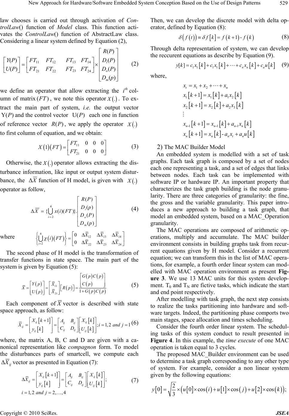 New Approach for Hardware/Software Embedded System Conception Based on the Use of Design Patterns529 law chooses is carried out through activation of Con- trolLaw() function of Model class. This function acti- vates the ControlLaw() function of AbstractLaw class. Considering a linear system defined by Equation (2), )( )( )( )( )( )( 24 14 23 13 2221 1211 pD PD PD PR FT FT FT FT FTFT FTFT PU PY m o i (2) we define an operator that allow extracting the col- umn of matrix, we note this operator. To ex- tract the main part of system, i.e. the output vector and the control vector each one in function of reference vector , we apply the operator th i )(FT .X )Y(P)U(P )(PR .X to first column of equation, and we obtain: 11 21 000 1000 FT XFT FT (3) Otherwise, theoperator allows extracting the dis- turbance information, like input or output system distur- bance, the .X X Δfunction of H model, is given with .X operator as follow, )( )( )( )( }))(({Δ 4 2 pD PD pD PR .FTixX m o i i (4) where 4 12 13 14 222 23 24 0 0 i XXX iFT XXX The second phase of H model is the transformation of transfer functions in state space. The main part of the system is given by Equation (5): 11 21 1 GpCp Yp Cp X XRp GpCp Up X (5) Each component of X vector is described with state space approach, as follow: 1;1,2 1 ij ij ij ij ij ij ij ij ij Xk Xk AB X iand j CD yk Uk (6) where, the matrix A, B, C and D are given with a ca- nonical representation like compagnon form. To model the disturbances parts of smartcell, we compute each ij XΔvector as presented in Equation (7): 1; 1,2 2,,4 ij ij ij ij ij ij ij ij ij X kX AB XCD Then, we can develop the discrete model with delta op- erator, defined by Equation (8): 1- f tfkfkf k (8) Through delta representation of system, we can develop the reccurent equations as describe by Equation (9). 11 11 [] nn u yk cxkcxkcxkcuk (9) where, 12 1112 2223 -1-1 -1 1 1 1 1- tn nnnn nnntn xxx x xkxk axk xkxk axk x kx k axk x kxkaxau k 2) The MAC Builder Model An embedded system is modelled with a set of task graphs. Each task graph is composed by a set of nodes each one representing a task, and a set of edges that links between nodes. Each task can be implemented with software IP or hardware IP. An important property that characterizes the task graph building is the node granu- larity. There are three categories of granularity: the fine, the gross and the variable granularity. This paper intro- duces a new approach to building a task graph, that model an embedded system, based on a MAC_Operation granularity. The MAC operations are composed of arithmetic op- erations, multiply and accumulate. The MAC builder environment consists in building graphs task from recur- rent equations given by H model. Consider a recurrent equation; we can transform this in the list of MAC opera- tions, for example, a fourth order linear system can mod- elled with MAC operation environment as present Fig- ure 3. We use 13 MAC units for this system develop- ment. T0 and TN are fictive tasks, which indicate the start and end point respectively. After modelling with task graph, the next step consists to realize the tasks partitioning into hardware and soft- ware targets. Indeed, the partitioning phase comports two main stages, space allocation and times scheduling. Consider the fourth order linear system. The schedul- ing tasks of this system conduct to result presented in Figure 4. In this example, the time execute of one MAC operation is taken equal to 3 cycles. The proposed MAC_Builder environment can be used to determine a task graph corresponding to any other type of system. For example, consider a non linear system given by the following equations: k y k iand j Uk (7) 2 00cos1 cos2cos; 3 yuiujuk Copyright © 2010 SciRes. JSEA 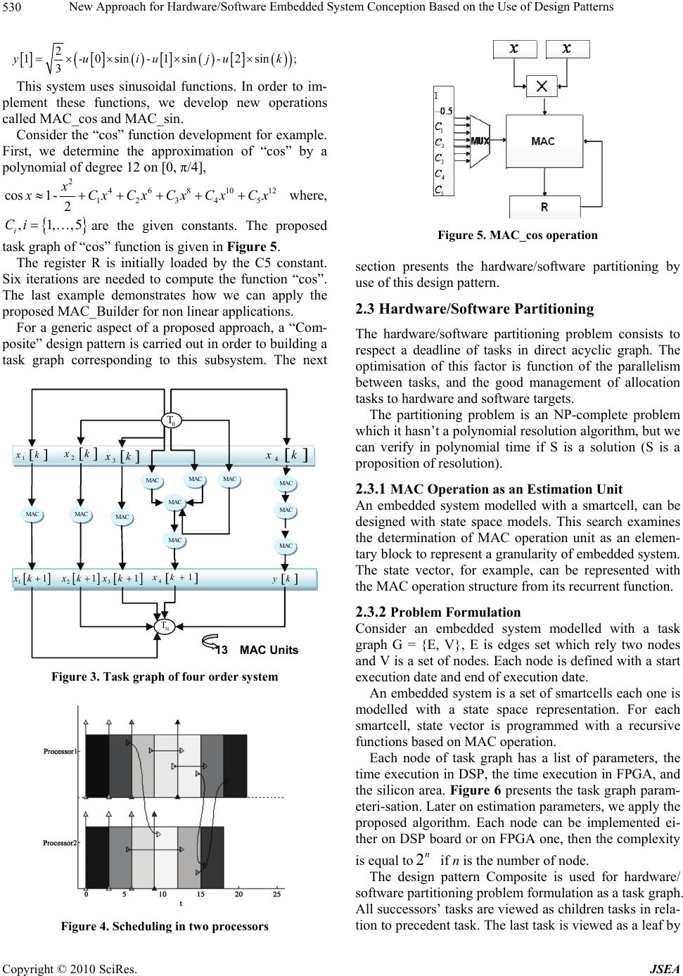 New Approach for Hardware/Software Embedded System Conception Based on the Use of Design Patterns 530 2 1-0sin -1sin-2sin; 3 yuiuju k This system uses sinusoidal functions. In order to im- plement these functions, we develop new operations called MAC_cos and MAC_sin. Consider the “cos” function development for example. First, we determine the approximation of “cos” by a polynomial of degree 12 on [0, π/4], 2 46810 1234 5 cos1- 2 x12 x CxCx Cx CxCx where, ,1,,5 i Ciare the given constants. The proposed task graph of “cos” function is given in Figure 5. The register R is initially loaded by the C5 constant. Six iterations are needed to compute the function “cos”. The last example demonstrates how we can apply the proposed MAC_Builder for non linear applications. For a generic aspect of a proposed approach, a “Com- posite” design pattern is carried out in order to building a task graph corresponding to this subsystem. The next 0 T N T 2 x k MAC 13 MAC Units 1 x k 3 x k 11xk 21xk 31xk 41xk yk 4 x k MAC MAC MAC MAC MAC MAC MAC MAC MAC MAC Figure 3. Task graph of four order system Figure 4. Scheduling in two processors Figure 5. MAC_cos operation section presents the hardware/software partitioning by use of this design pattern. 2.3 Hardware/Software Partitioning The hardware/software partitioning problem consists to respect a deadline of tasks in direct acyclic graph. The optimisation of this factor is function of the parallelism between tasks, and the good management of allocation tasks to hardware and software targets. The partitioning problem is an NP-complete problem which it hasn’t a polynomial resolution algorithm, but we can verify in polynomial time if S is a solution (S is a proposition of resolution). 2.3.1 MAC Operation as an Estimation Unit An embedded system modelled with a smartcell, can be designed with state space models. This search examines the determination of MAC operation unit as an elemen- tary block to represent a granularity of embedded system. The state vector, for example, can be represented with the MAC operation structure from its recurrent function. 2.3.2 Problem Formulation Consider an embedded system modelled with a task graph G = {E, V}, E is edges set which rely two nodes and V is a set of nodes. Each node is defined with a start execution date and end of execution date. An embedded system is a set of smartcells each one is modelled with a state space representation. For each smartcell, state vector is programmed with a recursive functions based on MAC operation. Each node of task graph has a list of parameters, the time execution in DSP, the time execution in FPGA, and the silicon area. Figure 6 presents the task graph param- eteri-sation. Later on estimation parameters, we apply the proposed algorithm. Each node can be implemented ei- ther on DSP board or on FPGA one, then the complexity is equal to if n is the number of node. 2n The design pattern Composite is used for hardware/ software partitioning problem formulation as a task graph. All successors’ tasks are viewed as children tasks in rela- tion to precedent task. The last task is viewed as a leaf by Copyright © 2010 SciRes. JSEA 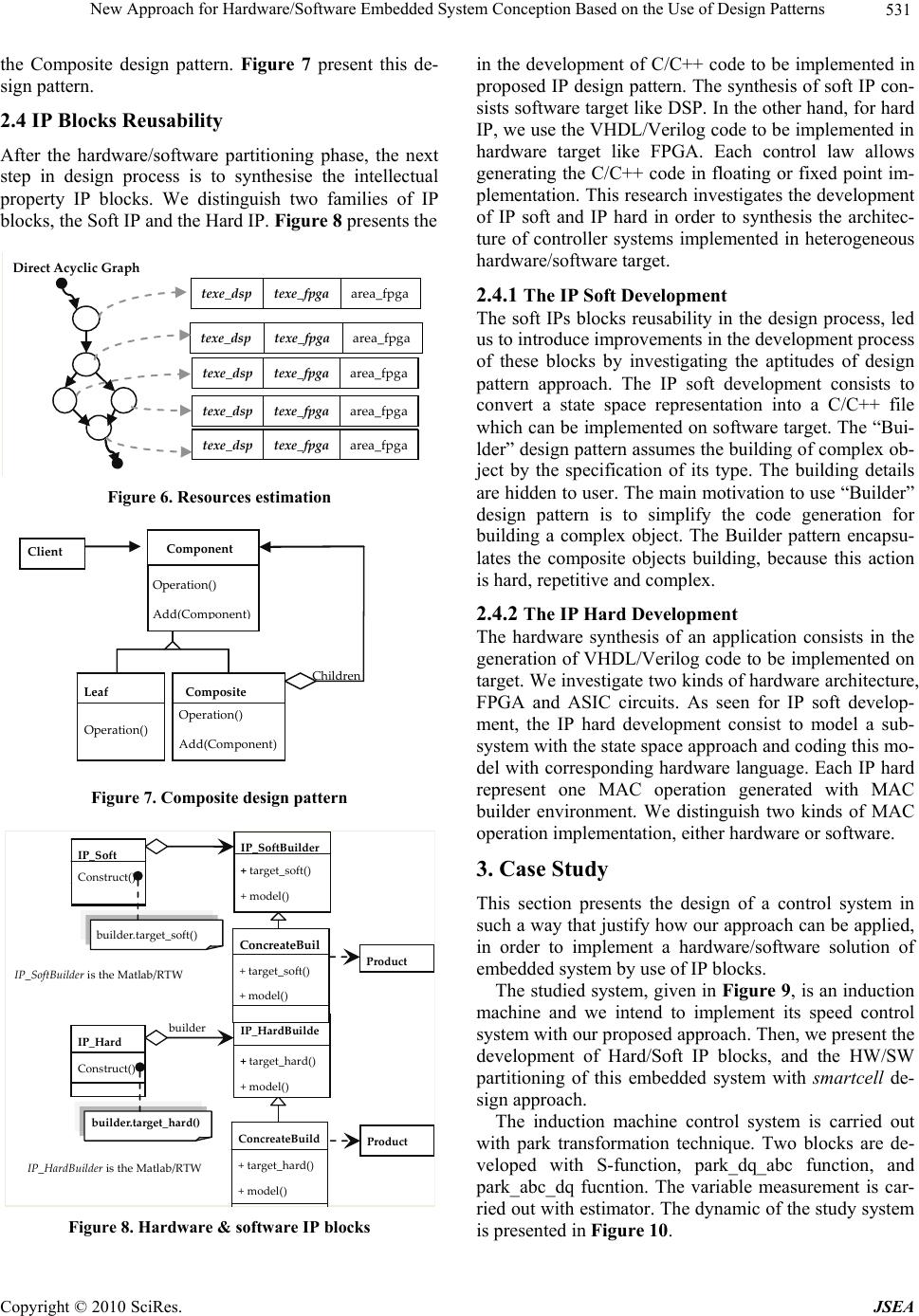 New Approach for Hardware/Software Embedded System Conception Based on the Use of Design Patterns531 the Composite design pattern. Figure 7 present this de- sign pattern. 2.4 IP Blocks Reusability After the hardware/software partitioning phase, the next step in design process is to synthesise the intellectual property IP blocks. We distinguish two families of IP blocks, the Soft IP and the Hard IP. Figure 8 presents the texe_dsptexe_fpgaarea_fpga texe_dsptexe_fpgaarea_fpga texe_dsptexe_fpgaarea_fpga texe_dsptexe_fpgaarea_fpga texe_dsptexe_fpgaarea_fpga DirectAcyclicGraph Figure 6. Resources estimation Com p osite Client Leaf Operation() Add(Component) Component Opera t io n ( ) A dd ( C o m po n e nt ) Oper at io n ( ) Childre n Figure 7. Composite design pattern IP_Hard IP_HardBuilde +target_hard() +model () builder IP_HardBuilderisthe Matlab/RTW Product Construct() builder.target_hard() IP_SoftIP _ SoftBuilder +target_soft() +model() Product Construct() builder.target_soft() IP_SoftBuilderistheMatlab/RTW ConcreateBui l +target_soft() +model () ConcreateBuild +target_hard() +model() Figure 8. Hardware & software IP blocks in the development of C/C++ code to be implemented in proposed IP design pattern. The synthesis of soft IP con- sists software target like DSP. In the other hand, for hard IP, we use the VHDL/Verilog code to be implemented in hardware target like FPGA. Each control law allows generating the C/C++ code in floating or fixed point im- plementation. This research investigates the development of IP soft and IP hard in order to synthesis the architec- ture of controller systems implemented in heterogeneous hardware/software target. 2.4.1 The IP Soft Development The soft IPs blocks reusability in the design process, led us to introduce improvements in the development process of these blocks by investigating the aptitudes of design pattern approach. The IP soft development consists to convert a state space representation into a C/C++ file which can be implemented on software target. The “Bui- lder” design pattern assumes the building of complex ob- ject by the specification of its type. The building details are hidden to user. The main motivation to use “Builder” design pattern is to simplify the code generation for building a complex object. The Builder pattern encapsu- lates the composite objects building, because this action is hard, repetitive and complex. 2.4.2 The IP Hard Development The hardware synthesis of an application consists in the generation of VHDL/Verilog code to be implemented on target. We investigate two kinds of hardware architecture, FPGA and ASIC circuits. As seen for IP soft develop- ment, the IP hard development consist to model a sub- system with the state space approach and coding this mo- del with corresponding hardware language. Each IP hard represent one MAC operation generated with MAC builder environment. We distinguish two kinds of MAC operation implementation, either hardware or software. 3. Case Study This section presents the design of a control system in such a way that justify how our approach can be applied, in order to implement a hardware/software solution of embedded system by use of IP blocks. The studied system, given in Figure 9, is an induction machine and we intend to implement its speed control system with our proposed approach. Then, we present the development of Hard/Soft IP blocks, and the HW/SW partitioning of this embedded system with smartcell de- sign approach. The induction machine control system is carried out with park transformation technique. Two blocks are de- veloped with S-function, park_dq_abc function, and park_abc_dq fucntion. The variable measurement is car- ried out with estimator. The dynamic of the study system is presented in Figure 10. Copyright © 2010 SciRes. JSEA 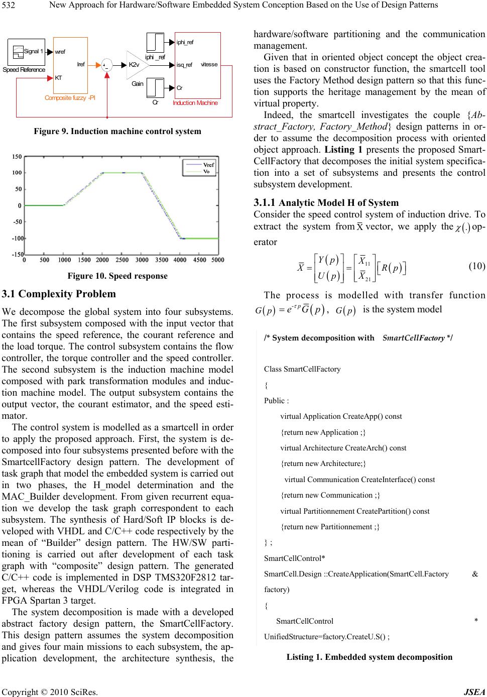 New Approach for Hardware/Software Embedded System Conception Based on the Use of Design Patterns 532 iphi_ref Speed Reference Signal 1 Induction Machine iphi_ref isq_ref Cr vi tesse Ga in K2v Composite fuzzy-PI wr e f KT Iref Cr Figure 9. Induction machine control system Figure 10. Speed response 3.1 Complexity Problem We decompose the global system into four subsystems. The first subsystem composed with the input vector that contains the speed reference, the courant reference and the load torque. The control subsystem contains the flow controller, the torque controller and the speed controller. The second subsystem is the induction machine model composed with park transformation modules and induc- tion machine model. The output subsystem contains the output vector, the courant estimator, and the speed esti- mator. The control system is modelled as a smartcell in order to apply the proposed approach. First, the system is de- composed into four subsystems presented before with the SmartcellFactory design pattern. The development of task graph that model the embedded system is carried out in two phases, the H_model determination and the MAC_Builder development. From given recurrent equa- tion we develop the task graph correspondent to each subsystem. The synthesis of Hard/Soft IP blocks is de- veloped with VHDL and C/C++ code respectively by the mean of “Builder” design pattern. The HW/SW parti- tioning is carried out after development of each task graph with “composite” design pattern. The generated C/C++ code is implemented in DSP TMS320F2812 tar- get, whereas the VHDL/Verilog code is integrated in FPGA Spartan 3 target. The system decomposition is made with a developed abstract factory design pattern, the SmartCellFactory. This design pattern assumes the system decomposition and gives four main missions to each subsystem, the ap- plication development, the architecture synthesis, the hardware/software partitioning and the communication management. Given that in oriented object concept the object crea- tion is based on constructor function, the smartcell tool uses the Factory Method design pattern so that this func- tion supports the heritage management by the mean of virtual property. Indeed, the smartcell investigates the couple {Ab- stract_Factory, Factory_Method} design patterns in or- der to assume the decomposition process with oriented object approach. Listing 1 presents the proposed Smart- CellFactory that decomposes the initial system specifica- tion into a set of subsystems and presents the control subsystem development. 3.1.1 Analytic Model H of System Consider the speed control system of induction drive. To extract the system from vector, we apply the . op- erator 11 21 Yp X X Rp Up X (10) The process is modelled with transfer function Gp -p eGp , Gp is the system model /*SystemdecompositionwithSmartCellFactory */ Class SmartCellFactory { Public : virtual Application CreateApp() const {return new Application ;} virtual Architecture CreateArch() const {return new Architecture;} virtual Communication CreateInterface() const {return new Communication ;} virtual Partitionnement CreatePartition() const {return new Partitionnement ;} } ; SmartCellControl* SmartCell.Design ::CreateApplication(SmartCell.Factory & factory) { SmartCellControl * UnifiedStructure=factory.CreateU.S() ; Listing 1. Embedded system decomposition Copyright © 2010 SciRes. JSEA 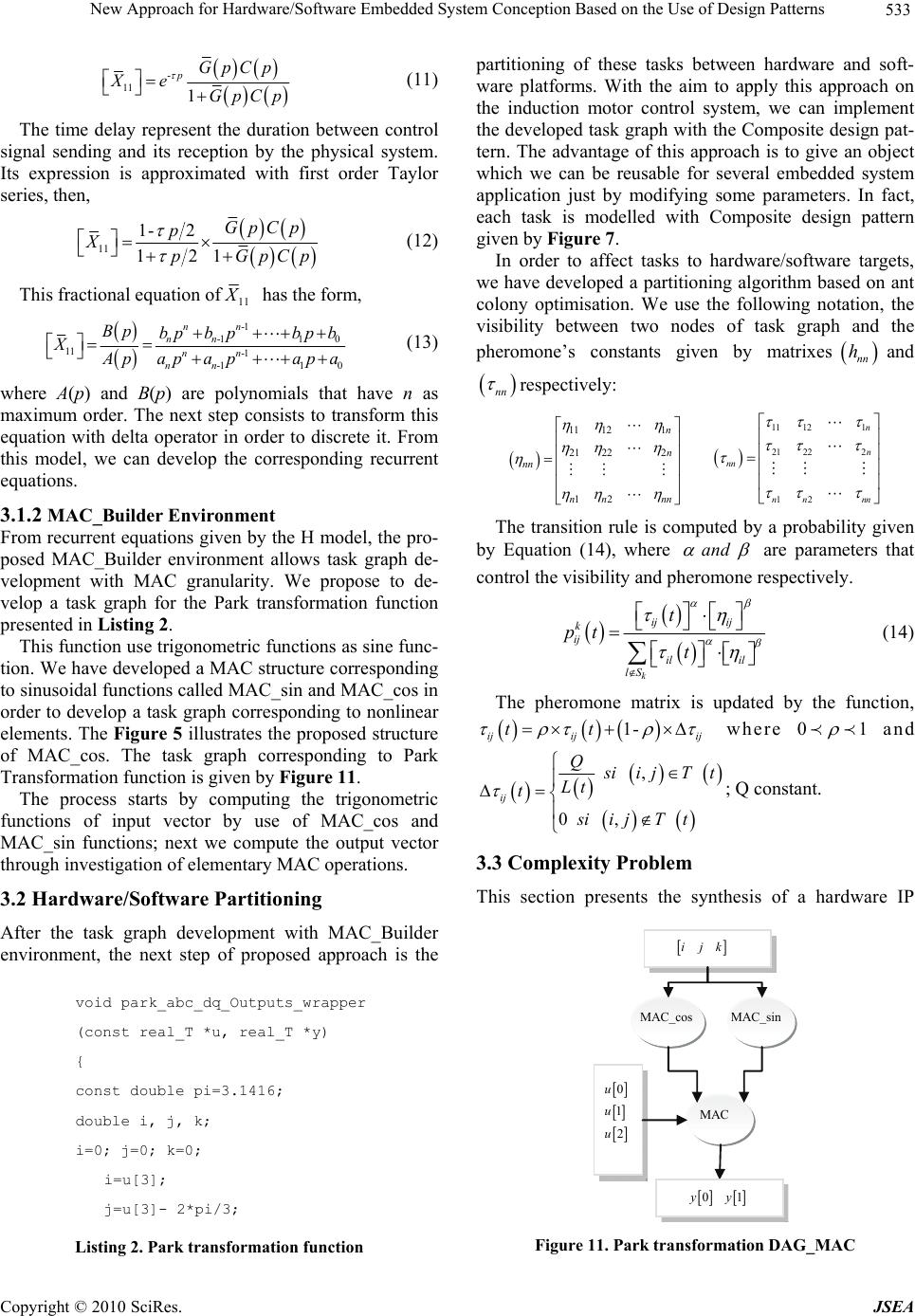 New Approach for Hardware/Software Embedded System Conception Based on the Use of Design Patterns533 - 11 1 pGpCp Xe GpC p (11) The time delay represent the duration between control signal sending and its reception by the physical system. Its expression is approximated with first order Taylor series, then, 11 1- 2 12 1 GpCp p XpGpCp (12) This fractional equation of11 X has the form, -1 -11 0 11 -1 -11 0 nn nn nn nn Bp bpb pbp b XApapa pap a (13) where A(p) and B(p) are polynomials that have n as maximum order. The next step consists to transform this equation with delta operator in order to discrete it. From this model, we can develop the corresponding recurrent equations. 3.1.2 MAC_Builder Environment From recurrent equations given by the H model, the pro- posed MAC_Builder environment allows task graph de- velopment with MAC granularity. We propose to de- velop a task graph for the Park transformation function presented in Listing 2. This function use trigonometric functions as sine func- tion. We have developed a MAC structure corresponding to sinusoidal functions called MAC_sin and MAC_cos in order to develop a task graph corresponding to nonlinear elements. The Figure 5 illustrates the proposed structure of MAC_cos. The task graph corresponding to Park Transformation function is given by Figure 11. The process starts by computing the trigonometric functions of input vector by use of MAC_cos and MAC_sin functions; next we compute the output vector through investigation of elementary MAC operations. 3.2 Hardware/Software Partitioning After the task graph development with MAC_Builder environment, the next step of proposed approach is the void park_abc_dq_Outputs_wrapper (const real_T *u, real_T *y) { const double pi=3.1416; double i, j, k; i=0; j=0; k=0; i=u[3]; j=u[3]- 2*pi/3; Listing 2. Park transformation function partitioning of these tasks between hardware and soft- ware platforms. With the aim to apply this approach on the induction motor control system, we can implement the developed task graph with the Composite design pat- tern. The advantage of this approach is to give an object which we can be reusable for several embedded system application just by modifying some parameters. In fact, each task is modelled with Composite design pattern given by Figure 7. In order to affect tasks to hardware/software targets, we have developed a partitioning algorithm based on ant colony optimisation. We use the following notation, the visibility between two nodes of task graph and the pheromone’s constants given by matrixes nn hand nn respectively: 11 121 21 222 12 n n nn nn nn 11 121 21 222 12 n n nn nn nn The transition rule is computed by a probability given by Equation (14), where and are parameters that control the visibility and pheromone respectively. k ij ij k ij il il lS t pt t (14) The pheromone matrix is updated by the function, 1- ij ijij tt where 01 and , 0 , ij Q s iijTt Lt t siijTt ; Q constant. 3.3 Complexity Problem This section presents the synthesis of a hardware IP 0 1 2 u u u MAC MAC_sin MAC_cos ijk 01 y y Figure 11. Park transformation DAG_MAC Copyright © 2010 SciRes. JSEA 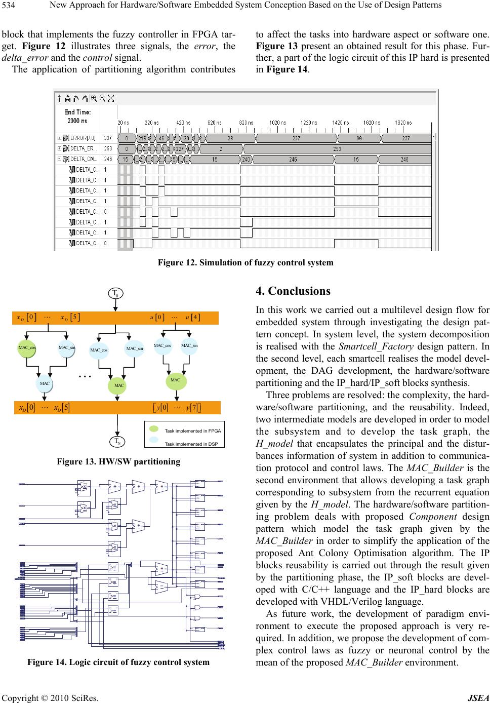 New Approach for Hardware/Software Embedded System Conception Based on the Use of Design Patterns Copyright © 2010 SciRes. JSEA 534 block that implements the fuzzy controller in FPGA tar- get. Figure 12 illustrates three signals, the error, the delta_error and the control signal. The application of partitioning algorithm contributes to affect the tasks into hardware aspect or software one. Figure 13 present an obtained result for this phase. Fur- ther, a part of the logic circuit of this IP hard is presented in Figure 14. Figure 12. Simulation of fuzzy control system 4. Conclusions 0 T N T 05 DD xx 04uu 07yy 05 DD xx MAC MAC_s in MAC_c o s MAC MAC_s i n MAC_c o s MAC MAC_s in MAC_c os Task implemented in FPGA Task implemented in DSP In this work we carried out a multilevel design flow for embedded system through investigating the design pat- tern concept. In system level, the system decomposition is realised with the Smartcell_Factory design pattern. In the second level, each smartcell realises the model devel- opment, the DAG development, the hardware/software partitioning and the IP_hard/IP_soft blocks synthesis. Three problems are resolved: the complexity, the hard- ware/software partitioning, and the reusability. Indeed, two intermediate models are developed in order to model the subsystem and to develop the task graph, the H_model that encapsulates the principal and the distur- bances information of system in addition to communica- tion protocol and control laws. The MAC_Builder is the second environment that allows developing a task graph corresponding to subsystem from the recurrent equation given by the H_model. The hardware/software partition- ing problem deals with proposed Component design Figure 13. HW/SW partitioning pattern which model the task graph given by the MAC_Builder in order to simplify the application of the proposed Ant Colony Optimisation algorithm. The IP blocks reusability is carried out through the result given by the partitioning phase, the IP_soft blocks are devel- oped with C/C++ language and the IP_hard blocks are developed with VHDL/Verilog language. As future work, the development of paradigm envi- ronment to execute the proposed approach is very re- quired. In addition, we propose the development of com- plex control laws as fuzzy or neuronal control by the mean of the proposed MAC_Builder environment. Figure 14. Logic circuit of fuzzy control system 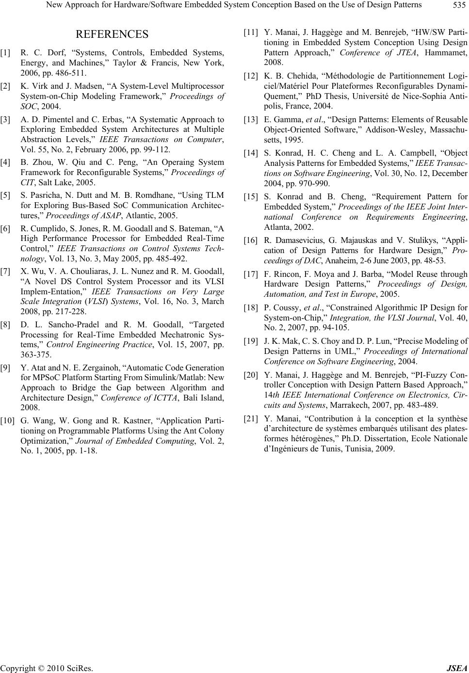 New Approach for Hardware/Software Embedded System Conception Based on the Use of Design Patterns535 REFERENCES [1] R. C. Dorf, “Systems, Controls, Embedded Systems, Energy, and Machines,” Taylor & Francis, New York, 2006, pp. 486-511. [2] K. Virk and J. Madsen, “A System-Level Multiprocessor System-on-Chip Modeling Framework,” Proceedings of SOC, 2004. [3] A. D. Pimentel and C. Erbas, “A Systematic Approach to Exploring Embedded System Architectures at Multiple Abstraction Levels,” IEEE Transactions on Computer, Vol. 55, No. 2, February 2006, pp. 99-112. [4] B. Zhou, W. Qiu and C. Peng, “An Operaing System Framework for Reconfigurable Systems,” Proceedings of CIT, Salt Lake, 2005. [5] S. Pasricha, N. Dutt and M. B. Romdhane, “Using TLM for Exploring Bus-Based SoC Communication Architec- tures,” Proceedings of ASAP, Atlantic, 2005. [6] R. Cumplido, S. Jones, R. M. Goodall and S. Bateman, “A High Performance Processor for Embedded Real-Time Control,” IEEE Transactions on Control Systems Tech- nology, Vol. 13, No. 3, May 2005, pp. 485-492. [7] X. Wu, V. A. Chouliaras, J. L. Nunez and R. M. Goodall, “A Novel DS Control System Processor and its VLSI Implem-Entation,” IEEE Transactions on Very Large Scale Integration (VLSI) Systems, Vol. 16, No. 3, March 2008, pp. 217-228. [8] D. L. Sancho-Pradel and R. M. Goodall, “Targeted Processing for Real-Time Embedded Mechatronic Sys- tems,” Control Engineering Practice, Vol. 15, 2007, pp. 363-375. [9] Y. Atat and N. E. Zergainoh, “Automatic Code Generation for MPSoC Platform Starting From Simulink/Matlab: New Approach to Bridge the Gap between Algorithm and Architecture Design,” Conference of ICTTA, Bali Island, 2008. [10] G. Wang, W. Gong and R. Kastner, “Application Parti- tioning on Programmable Platforms Using the Ant Colony Optimization,” Journal of Embedded Computing, Vol. 2, No. 1, 2005, pp. 1-18. [11] Y. Manai, J. Haggège and M. Benrejeb, “HW/SW Parti- tioning in Embedded System Conception Using Design Pattern Approach,” Conference of JTEA, Hammamet, 2008. [12] K. B. Chehida, “Méthodologie de Partitionnement Logi- ciel/Matériel Pour Plateformes Reconfigurables Dynami- Quement,” PhD Thesis, Université de Nice-Sophia Anti- polis, France, 2004. [13] E. Gamma, et al., “Design Patterns: Elements of Reusable Object-Oriented Software,” Addison-Wesley, Massachu- setts, 1995. [14] S. Konrad, H. C. Cheng and L. A. Campbell, “Object Analysis Patterns for Embedded Systems,” IEEE Transac- tions on Software Engineering, Vol. 30, No. 12, December 2004, pp. 970-990. [15] S. Konrad and B. Cheng, “Requirement Pattern for Embedded System,” Proceedings of the IEEE Joint Inter- national Conference on Requirements Engineering, Atlanta, 2002. [16] R. Damasevicius, G. Majauskas and V. Stulikys, “Appli- cation of Design Patterns for Hardware Design,” Pro- ceedings of DAC, Anaheim, 2-6 June 2003, pp. 48-53. [17] F. Rincon, F. Moya and J. Barba, “Model Reuse through Hardware Design Patterns,” Proceedings of Design, Automation, and Test in Europe, 2005. [18] P. Coussy, et al., “Constrained Algorithmic IP Design for System-on-Chip,” Integration, the VLSI Journal, Vol. 40, No. 2, 2007, pp. 94-105. [19] J. K. Mak, C. S. Choy and D. P. Lun, “Precise Modeling of Design Patterns in UML,” Proceedings of International Conference on Software Engineering, 2004. [20] Y. Manai, J. Haggège and M. Benrejeb, “PI-Fuzzy Con- troller Conception with Design Pattern Based Approach,” 14th IEEE International Conference on Electronics, Cir- cuits and Systems, Marrakech, 2007, pp. 483-489. [21] Y. Manai, “Contribution à la conception et la synthèse d’architecture de systèmes embarqués utilisant des plates- formes hétérogènes,” Ph.D. Dissertation, Ecole Nationale d’Ingénieurs de Tunis, Tunisia, 2009. Copyright © 2010 SciRes. JSEA |