Paper Menu >>
Journal Menu >>
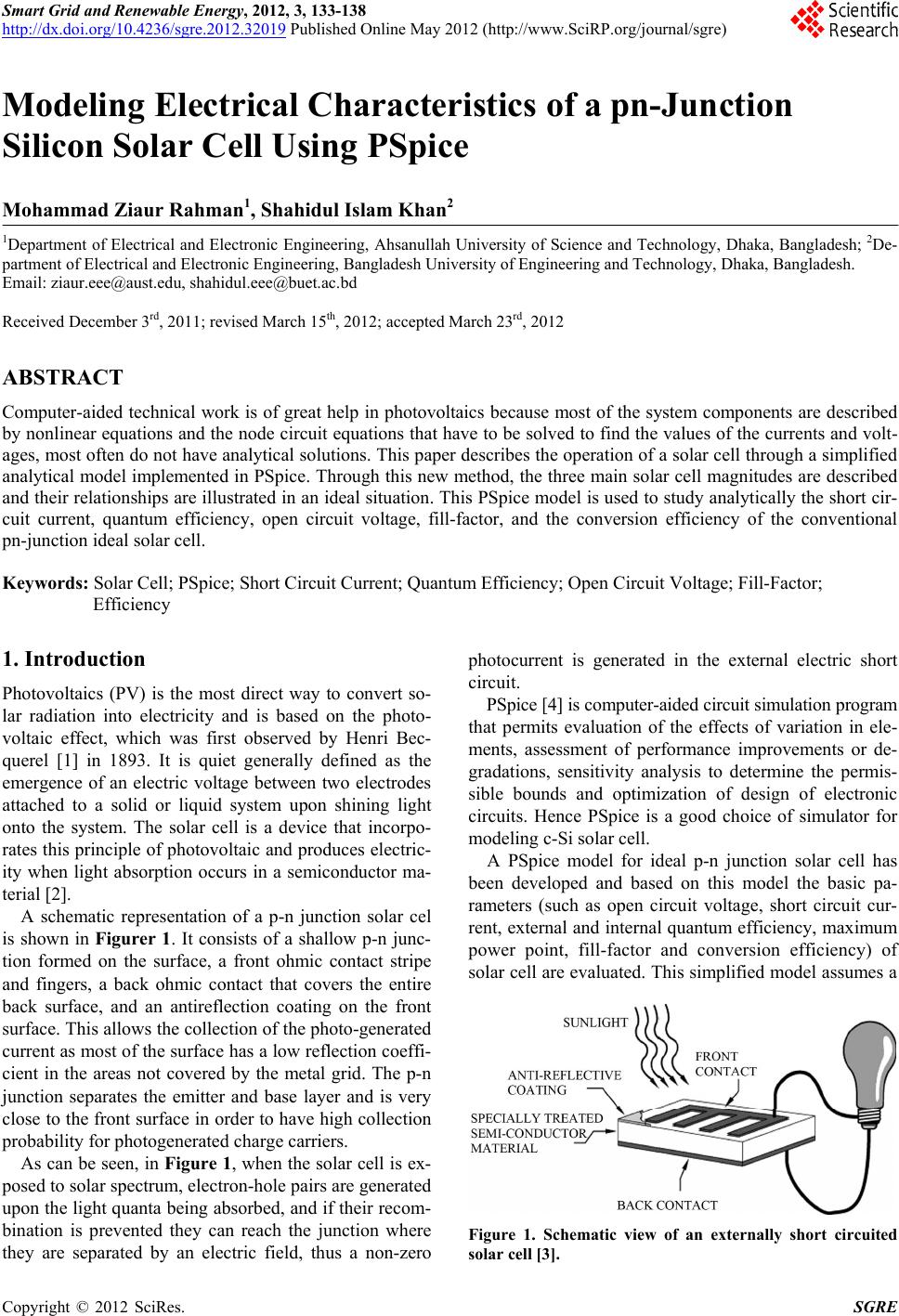 Smart Grid and Renewable Energy, 2012, 3, 133-138 http://dx.doi.org/10.4236/sgre.2012.32019 Published Online May 2012 (http://www.SciRP.org/journal/sgre) 1 Modeling Electrical Characteristics of a pn-Junction Silicon Solar Cell Using PSpice Mohammad Ziaur Rahman1, Shahidul Islam Khan2 1Department of Electrical and Electronic Engineering, Ahsanullah University of Science and Technology, Dhaka, Bangladesh; 2De- partment of Electrical and Electronic Engineering, Bangladesh University of Engineering and Technology, Dhaka, Bangladesh. Email: ziaur.eee@aust.edu, shahidul.eee@buet.ac.bd Received December 3rd, 2011; revised March 15th, 2012; accepted March 23rd, 2012 ABSTRACT Computer-aided technical work is of great help in photovoltaics because most of the system components are described by nonlinear equations and the node circuit equations that have to be solved to find the values of the currents and volt- ages, most often do not have analytical solutions. This paper describes the operation of a solar cell through a simplified analytical model implemented in PSpice. Through this new method, the three main solar cell magnitudes are described and their relationships are illustrated in an ideal situation. This PSpice model is used to study analytically the short cir- cuit current, quantum efficiency, open circuit voltage, fill-factor, and the conversion efficiency of the conventional pn-junction ideal solar cell. Keywords: Solar Cell; PSpice; Short Circuit Current; Quantum Efficiency; Open Circuit Voltage; Fill-Factor; Efficiency 1. Introduction Photovoltaics (PV) is the most direct way to convert so- lar radiation into electricity and is based on the photo- voltaic effect, which was first observed by Henri Bec- querel [1] in 1893. It is quiet generally defined as the emergence of an electric voltage between two electrodes attached to a solid or liquid system upon shining light onto the system. The solar cell is a device that incorpo- rates this principle of photovoltaic and produces electric- ity when light absorption occurs in a semiconductor ma- terial [2]. A schematic representation of a p-n junction solar cel is shown in Figurer 1. It consists of a shallow p-n junc- tion formed on the surface, a front ohmic contact stripe and fingers, a back ohmic contact that covers the entire back surface, and an antireflection coating on the front surface. This allows the collection of the photo-generated current as most of the surface has a low reflection coeffi- cient in the areas not covered by the metal grid. The p-n junction separates the emitter and base layer and is very close to the front surface in order to have high collection probability for photogenerated charge carriers. As can be seen, in Figure 1, when the solar cell is ex- posed to solar spectrum, electron-hole pairs are generated upon the light quanta being absorbed, and if their recom- bination is prevented they can reach the junction where they are separated by an electric field, thus a non-zero photocurrent is generated in the external electric short circuit. PSpice [4] is computer-aided circuit simulation program that permits evaluation of the effects of variation in ele- ments, assessment of performance improvements or de- gradations, sensitivity analysis to determine the permis- sible bounds and optimization of design of electronic circuits. Hence PSpice is a good choice of simulator for modeling c-Si solar cell. A PSpice model for ideal p-n junction solar cell has been developed and based on this model the basic pa- rameters (such as open circuit voltage, short circuit cur- rent, external and internal quantum efficiency, maximum power point, fill-factor and conversion efficiency) of solar cell are evaluated. This simplified model assumes a Figure 1. Schematic view of an externally short circuited solar cell [3]. Copyright © 2012 SciRes. SGRE 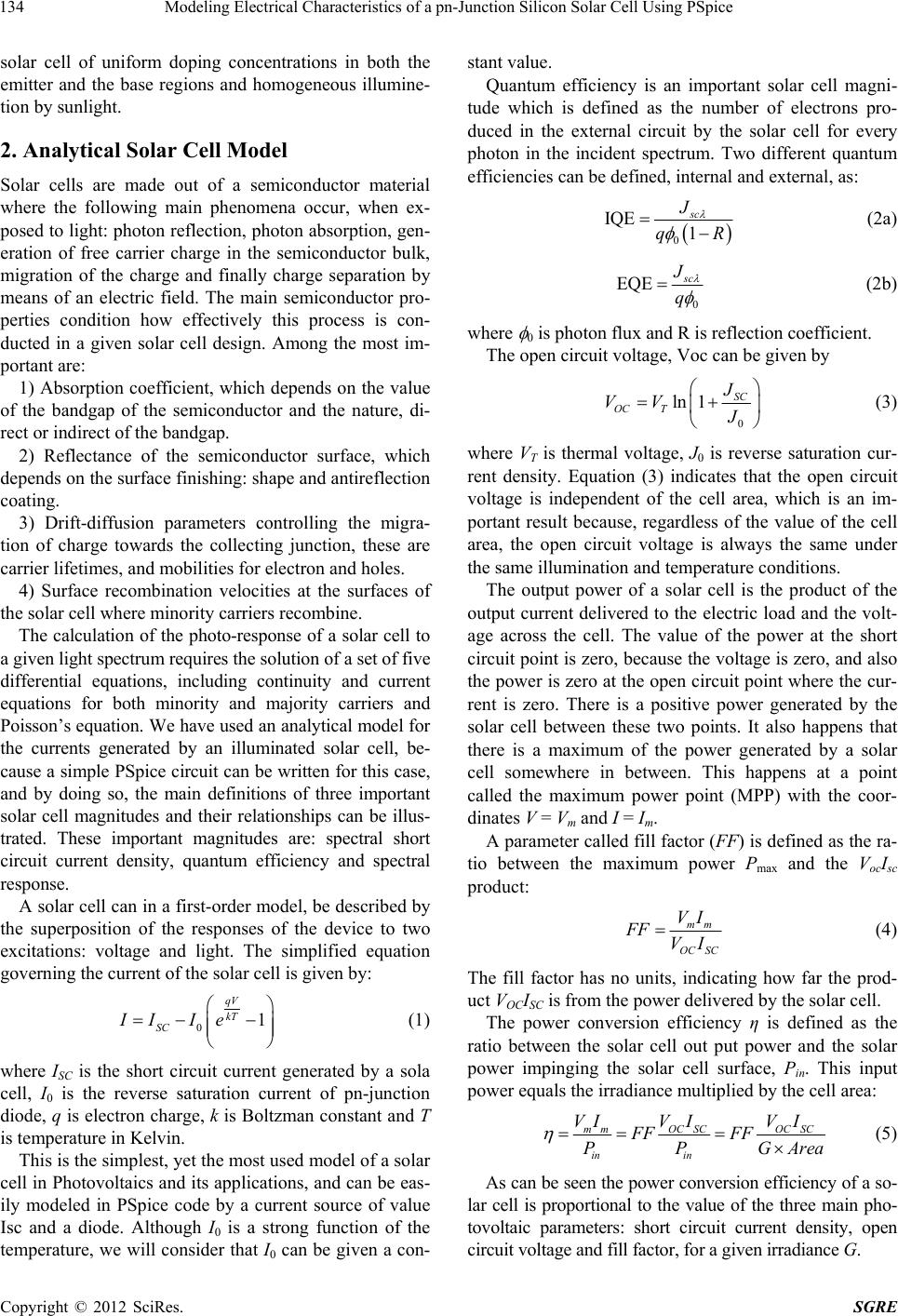 Modeling Electrical Characteristics of a pn-Junction Silicon Solar Cell Using PSpice 134 solar cell of uniform doping concentrations in both the emitter and the base regions and homogeneous illumine- tion by sunlight. 2. Analytical Solar Cell Model Solar cells are made out of a semiconductor material where the following main phenomena occur, when ex- posed to light: photon reflection, photon absorption, gen- eration of free carrier charge in the semiconductor bulk, migration of the charge and finally charge separation by means of an electric field. The main semiconductor pro- perties condition how effectively this process is con- ducted in a given solar cell design. Among the most im- portant are: 1) Absorption coefficient, which depends on the value of the bandgap of the semiconductor and the nature, di- rect or indirect of the bandgap. 2) Reflectance of the semiconductor surface, which depends on the surface finishing: shape and antireflection coating. 3) Drift-diffusion parameters controlling the migra- tion of charge towards the collecting junction, these are carrier lifetimes, and mobilities for electron and holes. 4) Surface recombination velocities at the surfaces of the solar cell where minority carriers recombine. The calculation of the photo-response of a solar cell to a given light spectrum requires the solution of a set of five differential equations, including continuity and current equations for both minority and majority carriers and Poisson’s equation. We have used an analytical model for the currents generated by an illuminated solar cell, be- cause a simple PSpice circuit can be written for this case, and by doing so, the main definitions of three important solar cell magnitudes and their relationships can be illus- trated. These important magnitudes are: spectral short circuit current density, quantum efficiency and spectral response. A solar cell can in a first-order model, be described by the superposition of the responses of the device to two excitations: voltage and light. The simplified equation governing the current of the solar cell is given by: 01 qV kT SC II Ie (1) where ISC is the short circuit current generated by a sola cell, I0 is the reverse saturation current of pn-junction diode, q is electron charge, k is Boltzman constant and T is temperature in Kelvin. This is the simplest, yet the most used model of a solar cell in Photovoltaics and its applications, and can be eas- ily modeled in PSpice code by a current source of value Isc and a diode. Although I0 is a strong function of the temperature, we will consider that I0 can be given a con- stant value. Quantum efficiency is an important solar cell magni- tude which is defined as the number of electrons pro- duced in the external circuit by the solar cell for every photon in the incident spectrum. Two different quantum efficiencies can be defined, internal and external, as: 0 IQE 1 sc J qR (2a) 0 EQE s c J q (2b) where 0 is photon flux and R is reflection coefficient. The open circuit voltage, Voc can be given by 0 ln 1SC OC T J VV J (3) where VT is thermal voltage, J0 is reverse saturation cur- rent density. Equation (3) indicates that the open circuit voltage is independent of the cell area, which is an im- portant result because, regardless of the value of the cell area, the open circuit voltage is always the same under the same illumination and temperature conditions. The output power of a solar cell is the product of the output current delivered to the electric load and the volt- age across the cell. The value of the power at the short circuit point is zero, because the voltage is zero, and also the power is zero at the open circuit point where the cur- rent is zero. There is a positive power generated by the solar cell between these two points. It also happens that there is a maximum of the power generated by a solar cell somewhere in between. This happens at a point called the maximum power point (MPP) with the coor- dinates V = Vm and I = Im. A parameter called fill factor (FF) is defined as the ra- tio between the maximum power Pmax and the VocIsc product: mm OC SC VI FF VI (4) The fill factor has no units, indicating how far the prod- uct VOCISC is from the power delivered by the solar cell. The power conversion efficiency η is defined as the ratio between the solar cell out put power and the solar power impinging the solar cell surface, Pin. This input power equals the irradiance multiplied by the cell area: m mOCSCOCSC in in VI VIVI FF FF PPGA rea (5) As can be seen the power conversion efficiency of a so- lar cell is proportional to the value of the three main pho- tovoltaic parameters: short circuit current density, open circuit voltage and fill factor, for a given irradiance G. Copyright © 2012 SciRes. SGRE 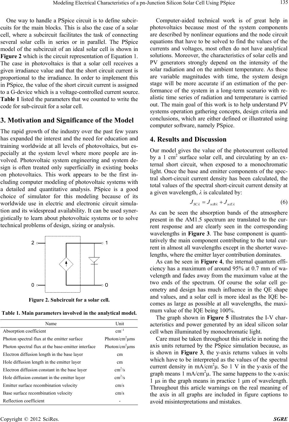 Modeling Electrical Characteristics of a pn-Junction Silicon Solar Cell Using PSpice 135 One way to handle a PSpice circuit is to define subcir- cuits for the main blocks. This is also the case of a solar cell, where a subcircuit facilitates the task of connecting several solar cells in series or in parallel. The PSpice model of the subcircuit of an ideal solar cell is shown in Figure 2 which is the circuit representation of Equation 1. The case in photovoltaics is that a solar cell receives a given irradiance value and that the short circuit current is proportional to the irradiance. In order to implement this in PSpice, the value of the short circuit current is assigned to a G-device which is a voltage-controlled current source. Table 1 listed the parameters that we counted to write the code for sub-circuit for a solar cell. 3. Motivation and Significance of the Model The rapid growth of the industry over the past few years has expanded the interest and the need for education and training worldwide at all levels of photovoltaics, but es- pecially at the system level where more people are in- volved. Photovoltaic system engineering and system de- sign is often treated only superficially in existing books on photovoltaics. This work appears to be the first in- cluding computer modeling of photovoltaic systems with a detailed and quantitative analysis. PSpice is a good choice of simulator for this modeling because of its worldwide use in electric and electronic circuit simula- tion and its widespread availability. It can be used syner- gistically to learn about photovoltaic systems or to solve technical problems of design, sizing or analysis. Figure 2. Subcircuit for a solar cell. Table 1. Main parameters involved in the analytical model. Name Unit Absorption coefficient cm–1 Photon spectral flux at the emitter surface Photon/cm2μms Photon spectral flux at the base-emitter interface Photon/cm2μms Electron diffusion length in the base layer cm Hole diffusion length in the emitter layer cm Electron diffusion constant in the base layer cm2/s Hole diffusion constant in the emitter layer cm2/s Emitter surface recombination velocity cm/s Base surface recombination velocity cm/s Reflection coefficient - Computer-aided technical work is of great help in photovoltaics because most of the system components are described by nonlinear equations and the node circuit equations that have to be solved to find the values of the currents and voltages, most often do not have analytical solutions. Moreover, the characteristics of solar cells and PV generators strongly depend on the intensity of the solar radiation and on the ambient temperature. As these are variable magnitudes with time, the system design stage will be more accurate if an estimation of the per- formance of the system in a long-term scenario with re- alistic time series of radiation and temperature is carried out. The main goal of this work is to help understand PV systems operation gathering concepts, design criteria and conclusions, which are either defined or illustrated using computer software, namely PSpice. 4. Results and Discussion Our model gives the value of the photocurrent collected by a 1 cm2 surface solar cell, and circulating by an ex- ternal short circuit, when exposed to a monochromatic light. Once the base and emitter components of the spec- tral short-circuit current density has been calculated, the total values of the spectral short-circuit current density at a given wavelength, λ is calculated by: SCscB scE J JJ (6) As can be seen the absorption bands of the atmosphere present in the AM1.5 spectrum are translated to the cur- rent response and are clearly seen in the corresponding wavelengths in Figure 3. The base component is quanti- tatively the main component contributing to the total cur- rent in almost all wavelengths except in the shorter wave- lengths, where the emitter layer contribution dominates. As can be seen in Figure 4, the internal quantum effi- ciency has a maximum of around 95% at 0.7 mm of wa- velength and fades away from the maximum value at the two ends of the spectrum. Of course the solar cell ge- ometry and design has much influence in the QE shape and values, and a solar cell is more ideal as the IQE be- comes as large as possible at all wavelengths, the maxi- mum value of the IQE being 100%. The graph shown in Figure 5 illustrates the I-V char- acteristics and power generated by an ideal silicon solar cell when illuminated by monochromatic light. Care must be taken throughout this article in noting the axis units returned by the PSpice simulation because, as is shown in Figure 3, the y-axis returns values in volts which have to be interpreted as the values of the spectral current density in mA/cm2μ. So 1 V in the y-axis of the graph means 1 mA/cm2μ. The same happens to the x-axis: 1 μs in the graph means in practice 1 μm of wavelength. Throughout this article warnings on the real meaning of the axis in all graphs are included in figure captions to avoid misinterpretations and mistakes. Copyright © 2012 SciRes. SGRE  Modeling Electrical Characteristics of a pn-Junction Silicon Solar Cell Using PSpice Copyright © 2012 SciRes. SGRE 136 (a) (b) (c) Figure 3. Spectral short circuit current densities for (a) emitter (b) base and (c) total short circuit current. [Warning: The units of the y-axis are to be interpreted as mA/cm2u for (a) and (b), and mA/cm2 for (c), and that of the x-axis are microns representing the wavelength]. 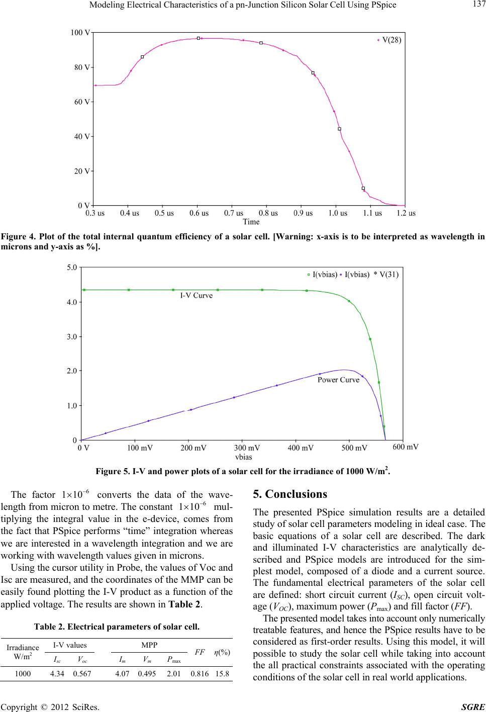 Modeling Electrical Characteristics of a pn-Junction Silicon Solar Cell Using PSpice 137 Figure 4. Plot of the total internal quantum efficiency of a solar cell. [Warning: x-axis is to be interpreted as wavelength in microns and y-axis as %]. Figure 5. I-V and power plots of a solar cell for the irradiance of 1000 W/m2. The factor converts the data of the wave- length from micron to metre. The constant 6 110 6 110 mul- tiplying the integral value in the e-device, comes from the fact that PSpice performs “time” integration whereas we are interested in a wavelength integration and we are working with wavelength values given in microns. Using the cursor utility in Probe, the values of Voc and Isc are measured, and the coordinates of the MMP can be easily found plotting the I-V product as a function of the applied voltage. The results are shown in Table 2. Table 2. Electrical parameters of solar cell. I-V values MPP Irradiance W/m2 Isc V oc ImVm P max FF η(%) 1000 4.34 0.567 4.07 0.495 2.01 0.81615.8 5. Conclusions The presented PSpice simulation results are a detailed study of solar cell parameters modeling in ideal case. The basic equations of a solar cell are described. The dark and illuminated I-V characteristics are analytically de- scribed and PSpice models are introduced for the sim- plest model, composed of a diode and a current source. The fundamental electrical parameters of the solar cell are defined: short circuit current (ISC), open circuit volt- age (VOC), maximum power (Pmax) and fill factor (FF). The presented model takes into account only numerically treatable features, and hence the PSpice results have to be considered as first-order results. Using this model, it will possible to study the solar cell while taking into account the all practical constraints associated with the operating conditions of the solar cell in real world applications. Copyright © 2012 SciRes. SGRE 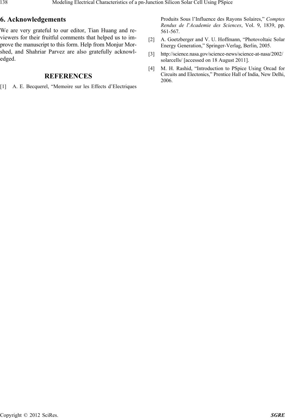 Modeling Electrical Characteristics of a pn-Junction Silicon Solar Cell Using PSpice 138 6. Acknowledgements We are very grateful to our editor, Tian Huang and re- viewers for their fruitful comments that helped us to im- prove the manuscript to this form. Help from Monjur Mor- shed, and Shahriar Parvez are also gratefully acknowl- edged. REFERENCES [1] A. E. Becquerel, “Memoire sur les Effects d’Electriques Produits Sous l’Influence des Rayons Solaires,” Comptes Rendus de l’Academie des Sciences, Vol. 9, 1839, pp. 561-567. [2] A. Goetzberger and V. U. Hoffmann, “Photovoltaic Solar Energy Generation,” Springer-Verlag, Berlin, 2005. [3] http://science.nasa.gov/science-news/science-at-nasa/2002/ solarcells/ [accessed on 18 August 2011]. [4] M. H. Rashid, “Introduction to PSpice Using Orcad for Circuits and Electonics,” Prentice Hall of India, New Delhi, 2006. Copyright © 2012 SciRes. SGRE |