Paper Menu >>
Journal Menu >>
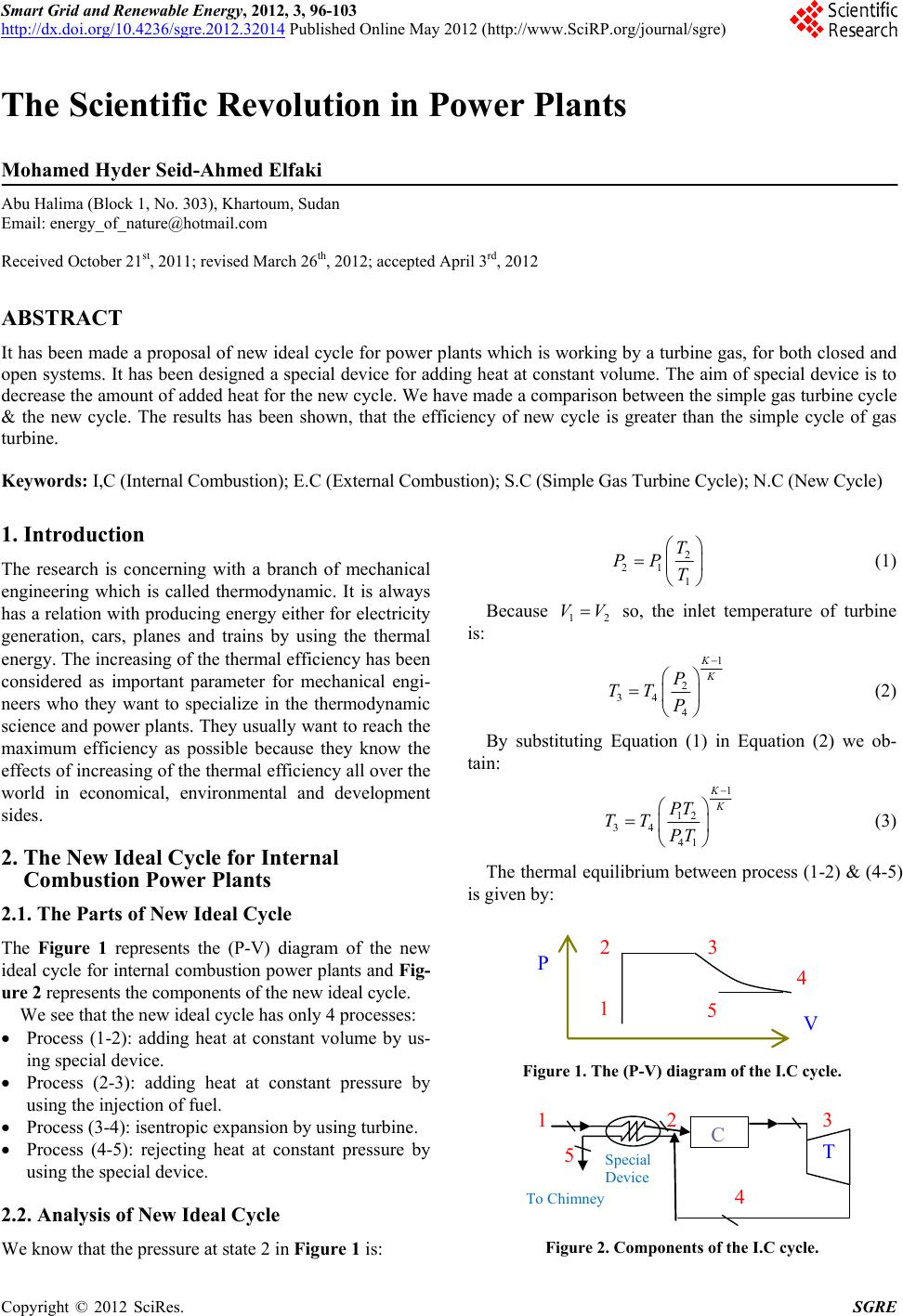 Smart Grid and Renewable Energy, 2012, 3, 96-103 http://dx.doi.org/10.4236/sgre.2012.32014 Published Online May 2012 (http://www.SciRP.org/journal/sgre) 1 The Scientific Revolution in Power Plants Mohamed Hyder Seid-Ahmed Elfaki Abu Halima (Block 1, No. 303), Khartoum, Sudan Email: energy_of_nature@hotmail.com Received October 21st, 2011; revised March 26th, 2012; accepted April 3rd, 2012 ABSTRACT It has been made a proposal of new ideal cycle for power plants which is working by a turbine gas, for both closed and open systems. It has been designed a special device for adding heat at constant volume. The aim of special device is to decrease the amount of added heat for the new cycle. We have made a comparison between the simple gas turbine cycle & the new cycle. The results has been shown, that the efficiency of new cycle is greater than the simple cycle of gas turbine. Keywords: I,C (Internal Combustion); E.C (External Combustion); S.C (Simple Gas Turbine Cycle); N.C (New Cycle) 1. Introduction The research is concerning with a branch of mechanical engineering which is called thermodynamic. It is always has a relation with producing energy either for electricity generation, cars, planes and trains by using the thermal energy. The increasing of the thermal efficiency has been considered as important parameter for mechanical engi- neers who they want to specialize in the thermodynamic science and power plants. They usually want to reach the maximum efficiency as possible because they know the effects of increasing of the thermal efficiency all over the world in economical, environmental and development sides. 2. The New Ideal Cycle for Internal Combustion Power Plants 2.1. The Parts of New Ideal Cycle The Figure 1 represents the (P-V) diagram of the new ideal cycle for internal combustion power plants and Fig- ure 2 represents the components of the new ideal cycle. We see that the new ideal cycle has only 4 processes: Process (1-2): adding heat at constant volume by us- ing special device. Process (2-3): adding heat at constant pressure by using the injection of fuel. Process (3-4): isentropic expansion by using turbine. Process (4-5): rejecting heat at constant pressure by using the special device. 2.2. Analysis of New Ideal Cycle We know that the pressure at state 2 in Figure 1 is: 2 21 1 T PP T (1) Because 1 VV 2 so, the inlet temperature of turbine is: 1 2 34 4 K K P TT P (2) By substituting Equation (1) in Equation (2) we ob- tain: 1 12 34 41 K K PT TT PT (3) The thermal equilibrium between process (1-2) & (4-5) is given by: P 1 2 3 4 5 V Figure 1. The (P-V) diagram of the I.C cycle. T 2 To Chimney C 5 Special Device 4 1 3 Figure 2. Components of the I.C cycle. Copyright © 2012 SciRes. SGRE 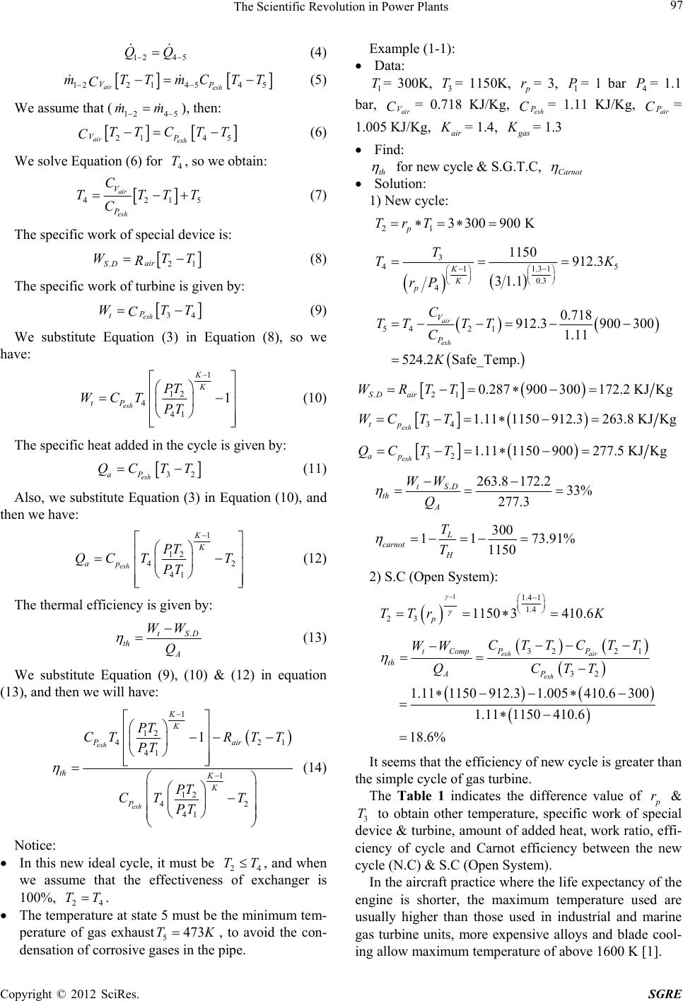 The Scientific Revolution in Power Plants 97 12 45 QQ (4) 122 1454 5 air exh VP mTTmCT C T (5) We assume that (), then: 12 45 mm 21 45 air exh VP TT C TT C (6) We solve Equation (6) for , so we obtain: 4 T 421 air exh V P C TTT C 5 T (7) The specific work of special device is: .2 air SD WT R 1 T (8) The specific work of turbine is given by: 34 exh P t WT C T (9) We substitute Equation (3) in Equation (8), so we have: 1 12 4 41 1 exh K K tP PT WCT PT (10) The specific heat added in the cycle is given by: 32 exh aP QC TT (11) Also, we substitute Equation (3) in Equation (10), and then we have: 1 12 4 41 exh K K ap PT QC TT PT 2 (12) The thermal efficiency is given by: .tSD th A WW Q (13) We substitute Equation (9), (10) & (12) in equation (13), and then we will have: 1 12 42 41 1 12 42 41 1 exh exh K K Pa th K K P PT CTRT T PT PT CT T PT 1ir (14) Notice: In this new ideal cycle, it must be 24 TT, and when we assume that the effectiveness of exchanger is 100%, TT. 24 The temperature at state 5 must be the minimum tem- perature of gas exhaust5473TK , to avoid the con- densation of corrosive gases in the pipe. Example (1-1): Data: 1 T= 300K, = 1150K, 3 T p r ex P C = 3, = 1 bar = 1.1 bar, = 0.718 KJ/Kg, = 1.11 KJ/Kg, = 1.005 KJ/Kg, 1 P4 P C air V Chair P air K = 1.4, g as K = 1.3 Find: th for new cycle & S.G.T.C, Carnot Solution: 1) New cycle: 21 3300900 K p TrT 3 45 11.31 0.3 4 1150 912.3 31.1 K K p T TK rP 54 21 0.718 912.3900 300 1.11 524.2Safe_Temp. air exh V P C TT TT C K .21 0.287900300172.2 KJKg SD air WRTT 34 1.111150912.3263.8 KJKg exh tp WC TT 32 1.111150900277.5 KJKg exh ap QC TT .263.8 172.233% 277.3 tSD th A WW Q 300 1 173.91% 1150 L carnot H T T 2) S.C (Open System): 11.4 1 1.4 23 1150 3410.6 p TTr K 32 21 32 1.111150 912.31.005410.6 300 1.111150 410.6 18.6% exh air exh PP tComp th AP CTTCTT WW QCTT It seems that the efficiency of new cycle is greater than the simple cycle of gas turbine. The Table 1 indicates the difference value of p r & 3 to obtain other temperature, specific work of special device & turbine, amount of added heat, work ratio, effi- ciency of cycle and Carnot efficiency between the new cycle (N.C) & S.C (Open System). T In the aircraft practice where the life expectancy of the engine is shorter, the maximum temperature used are usually higher than those used in industrial and marine gas turbine units, more expensive alloys and blade cool- ing allow maximum temperature of above 1600 K [1]. Copyright © 2012 SciRes. SGRE 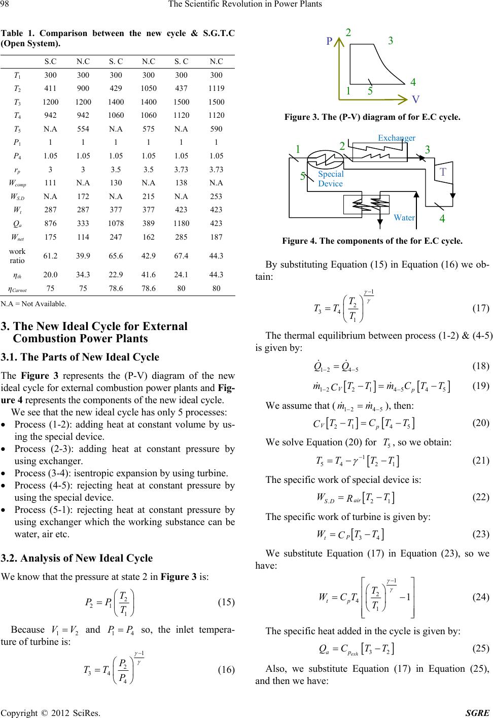 The Scientific Revolution in Power Plants 98 Table 1. Comparison between the new cycle & S.G.T.C (Open System). S.C N.C S. C N.C S. C N.C T1 300 300 300 300 300 300 T2 411 900 429 1050 437 1119 T3 1200 1200 1400 1400 1500 1500 T4 942 942 1060 1060 1120 1120 T5 N.A 554 N.A 575 N.A 590 P1 1 1 1 1 1 1 P4 1.05 1.05 1.05 1.05 1.05 1.05 rp 3 3 3.5 3.5 3.73 3.73 Wcomp 111 N.A 130 N.A 138 N.A WS.D N.A 172 N.A 215 N.A 253 Wt 287 287 377 377 423 423 Qa 876 333 1078 389 1180 423 Wnet 175 114 247 162 285 187 work ratio 61.2 39.9 65.6 42.9 67.4 44.3 ηth 20.0 34.3 22.9 41.6 24.1 44.3 ηCarnot 75 75 78.6 78.6 80 80 N.A = Not Available. 3. The New Ideal Cycle for External Combustion Power Plants 3.1. The Parts of New Ideal Cycle The Figure 3 represents the (P-V) diagram of the new ideal cycle for external combustion power plants and Fig- ure 4 represents the components of the new ideal cycle. We see that the new ideal cycle has only 5 processes: Process (1-2): adding heat at constant volume by us- ing the special device. Process (2-3): adding heat at constant pressure by using exchanger. Process (3-4): isentropic expansion by using turbine. Process (4-5): rejecting heat at constant pressure by using the special device. Process (5-1): rejecting heat at constant pressure by using exchanger which the working substance can be water, air etc. 3.2. Analysis of New Ideal Cycle We know that the pressure at state 2 in Figure 3 is: 2 21 1 T PP T (15) Because 1 and so, the inlet tempera- ture of turbine is: 2 4 VV1 PP 1 2 34 4 P TT P (16) 3 14 5 V 2 P Figure 3. The (P-V) diagram of for E.C cycle. T 12 3 4 5 Special Device Exchange r Water Figure 4. The components of the for E.C cycle. By substituting Equation (15) in Equation (16) we ob- tain: 1 2 34 1 T TT T (17) The thermal equilibrium between process (1-2) & (4-5) is given by: 12 45 QQ (18) 1221454 5 Vp mTTmCTT C (19) We assume that (12 45 mm ), then: 21 45 Vp TT CTT C (20) We solve Equation (20) for , so we obtain: 5 T 1 54 21 TT TT (21) The specific work of special device is: .2 air SD WT R1 T (22) The specific work of turbine is given by: 34 P t WTT C (23) We substitute Equation (17) in Equation (23), so we have: 1 2 4 1 1 tp T WCT T (24) The specific heat added in the cycle is given by: 32 exh ap QC TT (25) Also, we substitute Equation (17) in Equation (25), and then we have: Copyright © 2012 SciRes. SGRE 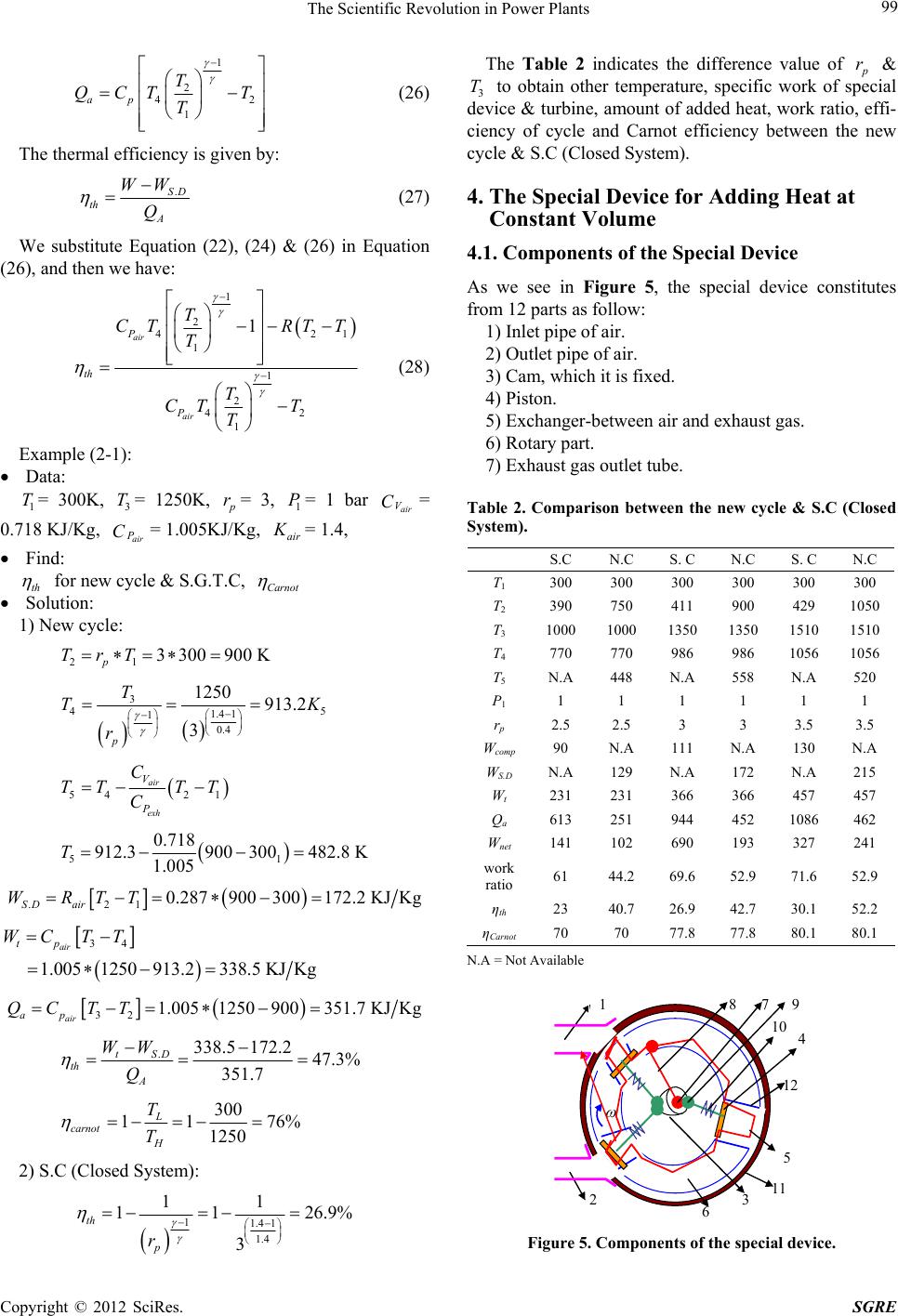 The Scientific Revolution in Power Plants 99 1 2 4 1 ap T QCT T T 2 (26) The thermal efficiency is given by: .SD th A WW Q (27) We substitute Equation (22), (24) & (26) in Equation (26), and then we have: 1 2 42 1 1 2 42 1 1 air air P th P T CTRT T T T CT T T 1 (28) Example (2-1): Data: 1 T= 300K, = 1250K, 3 T p r= 3, = 1 bar = 0.718 KJ/Kg, = 1.005KJ/Kg, 1 P air air V C ai P Cr K = 1.4, Find: th for new cycle & S.G.T.C, Carnot Solution: 1) New cycle: 21 3300900 K p TrT 3 4 1.4 1 1 0.4 1250 913.2 3 p T TK r 5 54 21 air exh V P C TT TT C 51 0.718 912.3900300482.8 K 1.005 T .21 0.287900300172.2 KJKg SD air WRTT 34 1.0051250913.2338.5 KJKg air tp WC TT 32 1.0051250900351.7 KJKg air ap QC TT .338.5 172.247.3% 351.7 tSD th A WW Q 300 11 76 1250 L carnot H T T % 2) S.C (Closed System): 11.4 1 1.4 11 11 26.9% 3 th p r The Table 2 indicates the difference value of p r & 3 to obtain other temperature, specific work of special device & turbine, amount of added heat, work ratio, effi- ciency of cycle and Carnot efficiency between the new cycle & S.C (Closed System). T 4. The Special Device for Adding Heat at Constant Volume 4.1. Components of the Special Device As we see in Figure 5, the special device constitutes from 12 parts as follow: 1) Inlet pipe of air. 2) Outlet pipe of air. 3) Cam, which it is fixed. 4) Piston. 5) Exchanger-between air and exhaust gas. 6) Rotary part. 7) Exhaust gas outlet tube. Table 2. Comparison between the new cycle & S.C (Closed System). S.C N.C S. C N.C S. C N.C T1 300 300 300 300 300 300 T2 390 750 411 900 429 1050 T3 1000 1000 1350 1350 1510 1510 T4 770 770 986 986 1056 1056 T5 N.A 448 N.A 558 N.A 520 P1 1 1 1 1 1 1 rp 2.5 2.5 3 3 3.5 3.5 Wcomp 90 N.A 111 N.A 130 N.A WS.D N.A 129 N.A 172 N.A 215 Wt 231 231 366 366 457 457 Qa 613 251 944 452 1086 462 Wnet 141 102 690 193 327 241 work ratio 61 44.2 69.6 52.9 71.6 52.9 ηth 23 40.7 26.9 42.7 30.1 52.2 ηCarnot 70 70 77.8 77.8 80.1 80.1 N.A = Not Available 7 9 12 6 3 2 11 5 10 4 8 1 Figure 5. Components of the special device. Copyright © 2012 SciRes. SGRE 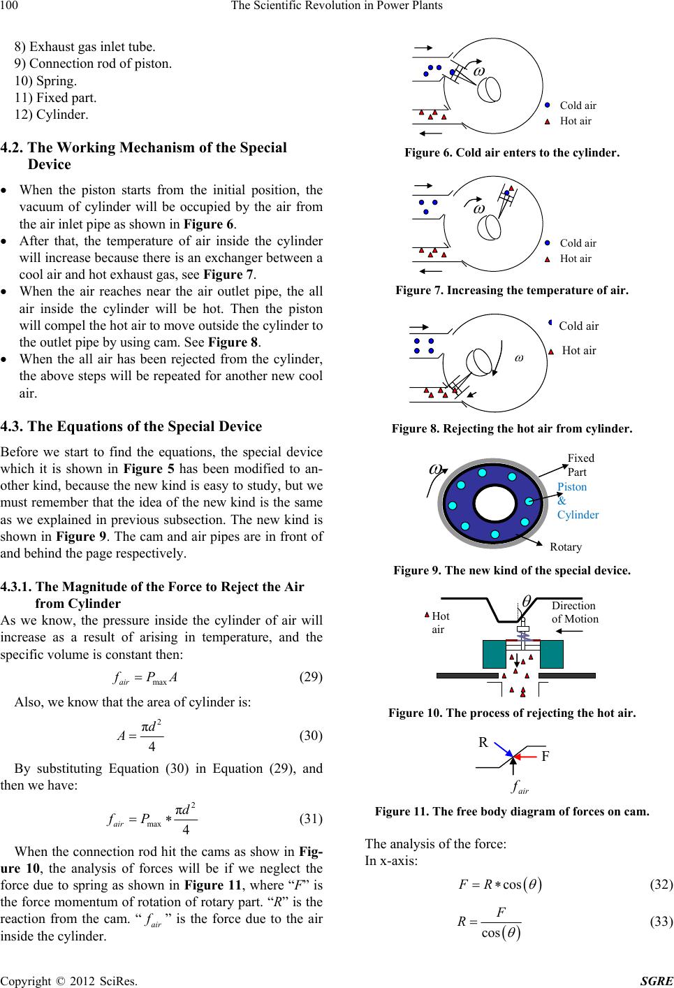 The Scientific Revolution in Power Plants 100 8) Exhaust gas inlet tube. 9) Connection rod of piston. 10) Spring. 11) Fixed part. 12) Cylinder. 4.2. The Working Mechanism of the Special Device When the piston starts from the initial position, the vacuum of cylinder will be occupied by the air from the air inlet pipe as shown in Figure 6. After that, the temperature of air inside the cylinder will increase because there is an exchanger between a cool air and hot exhaust gas, see Figure 7. When the air reaches near the air outlet pipe, the all air inside the cylinder will be hot. Then the piston will compel the hot air to move outside the cylinder to the outlet pipe by using cam. See Figure 8. When the all air has been rejected from the cylinder, the above steps will be repeated for another new cool air. 4.3. The Equations of the Special Device Before we start to find the equations, the special device which it is shown in Figure 5 has been modified to an- other kind, because the new kind is easy to study, but we must remember that the idea of the new kind is the same as we explained in previous subsection. The new kind is shown in Figure 9. The cam and air pipes are in front of and behind the page respectively. 4.3.1. The Magnitude of th e F orce to Re ject the Air from Cylinder As we know, the pressure inside the cylinder of air will increase as a result of arising in temperature, and the specific volume is constant then: maxair fPA (29) Also, we know that the area of cylinder is: 2 π 4 d A (30) By substituting Equation (30) in Equation (29), and then we have: 2 max π 4 air d fP (31) When the connection rod hit the cams as show in Fig- ure 10, the analysis of forces will be if we neglect the force due to spring as shown in Figure 11, where “F” is the force momentum of rotation of rotary part. “R” is the reaction from the cam. “air f ” is the force due to the air inside the cylinder. Cold air Hot air Figure 6. Cold air enters to the cylinder. Cold air Hot air Figure 7. Increasing the temperature of air. Cold air Hot ai r Figure 8. Rejecting the hot air from cylinder. Fixed Part Piston & Cylinder Rotary Figure 9. The new kind of the special device. Direction of Motion Hot air Figure 10. The process of rejecting the hot air. R F ai r f Figure 11. The free body diagram of forces on cam. The analysis of the force: In x-axis: cosFR (32) cos F R (33) Copyright © 2012 SciRes. SGRE 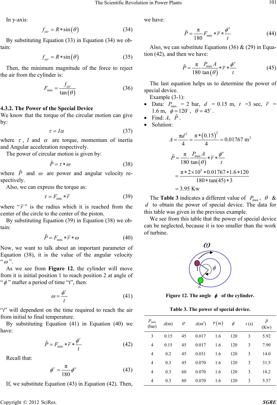 The Scientific Revolution in Power Plants 101 In y-axis: sin air fR (34) By substituting Equation (33) in Equation (34) we ob- tain: sin air fR (35) Then, the minimum magnitude of the force to reject the air from the cylinder is: min tan air f F (36) 4.3.2. The Power of the Special Device We know that the torque of the circular motion can give by: I (37) where , I and are torque, momentum of inertia and Angular acceleration respectively. The power of circular motion is given by: P (38) where and P are power and angular velocity re- spectively. Also, we can express the torque as: min F r (39) where “r” is the radius which it is reached from the center of the circle to the center of the piston. By substituting Equation (39) in Equation (38) we ob- tain: min PF r (40) Now, we want to talk about an important parameter of Equation (38), it is the value of the angular velocity “ ”. As we see from Figure 12, the cylinder will move from it is initial position 1 to reach position 2 at angle of “ ” mafter a period of time “t”, then: r t (41) “t” will dependent on the time required to reach the air from initial to final temperature. By substituting Equation (41) in Equation (40) we have: min r PFrt (42) Recall that: π 180 ro (43) If, we substitute Equation (43) in Equation (42). Then, we have: min π 180 o PFr t (44) Also, we can substitute Equations (36) & (29) in Equa- tion (42), and then we have: max π 180 tan o PA Pt r (45) The last equation helps us to determine the power of special device. Example (3-1): Data: max P = 2 bar, d = 0.15 m, t =3 sec, r = 1.6 m, 120 , 45 . Find: A, P . Solution: 2 2 2 π0.15 π0.01767 m 44 d A max 5 π 180 tan π2100.01767 1.6 120 180tan(45) 3 3.95 Kw o PA Pr t The Tab l e 3 indicates a different value of max , P & to obtain the power of special device. The data for this table was given in the previous example. d We see from this table that the power of special device can be neglected, because it is too smaller than the work of turbine. 1 2 Figure 12. The angle of the cylinde r . Table 3. The power of special device. Pmax (bar) d(m) θ˚ A(m2) rm t (s)P (Kw) 3 0.1545 0.0171.6 120 3 5.92 4 0.1545 0.0171.6 120 3 7.90 4 0.2 45 0.0311.6 120 3 14.0 4 0.3 45 0.0701.6 120 3 31.5 4 0.3 60 0.0701.6 120 3 18.2 4 0.3 80 0.0701.6 120 3 5.57 Copyright © 2012 SciRes. SGRE 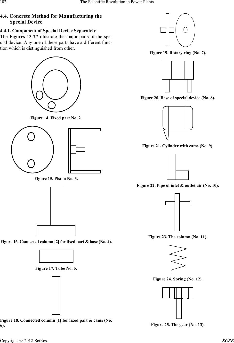 The Scientific Revolution in Power Plants 102 4.4. Concrete Method for Manufacturing the Special Device 4.4.1. Component of Special Device Separately The Figures 13-27 illustrate the major parts of the spe- cial device. Any one of these parts have a different func- tion which is distinguished from other. Figure 14. Fixed part No. 2. Figure 15. Piston No. 3. Figure 16. Connected column [2] for fixed pa rt & b as e (N o . 4) . Figure 17. Tube No. 5. Figure 18. Connected column [1] for fixed part & cams (No. 6). Figure 19. Rotary ring (No. 7). Figure 20. Base of special device (No. 8). Figure 21. Cylinder with cams (No. 9). Figure 22. Pipe of inlet & outlet air (No. 10). Figure 23. The column (No. 11). Figure 24. Spring (No. 12). Figure 25. The gear (No. 13). Copyright © 2012 SciRes. SGRE 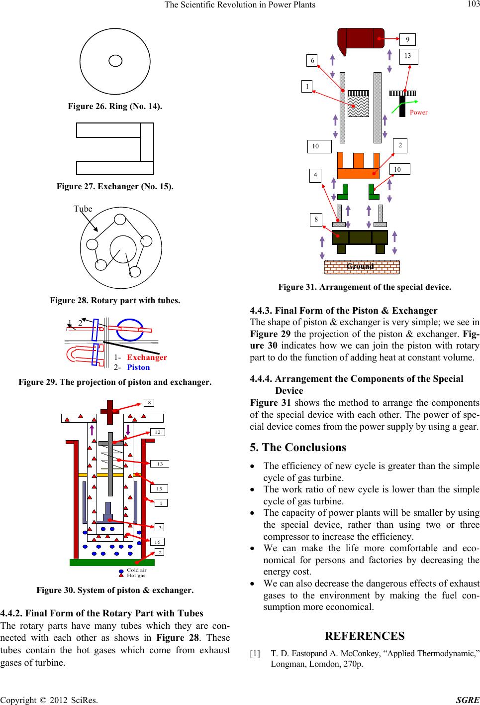 The Scientific Revolution in Power Plants Copyright © 2012 SciRes. SGRE 103 1 9 Ground Figure 26. Ring (No. 14). Figure 27. Exchanger (No. 15). Tube Figure 28. Rotary part with tubes. 1 2 1- Exchanger 2- Pist on Figure 29. The projection of piston and exchanger. 15 12 16 13 1 8 3 Cold air Hot gas 2 Figure 30. System of piston & exchanger. 4.4.2. Final Form of the Rotary Part with Tubes The rotary parts have many tubes which they are con- nected with each other as shows in Figure 28. These tubes contain the hot gases which come from exhaust ases of turbine. g Power 13 6 2 10 4 8 10 Figure 31. Arrangement of the special device. 4.4.3. Final Form of the Piston & Exchanger The shape of piston & exchanger is very simple; we see in Figure 29 the projection of the piston & exchanger. Fig- ure 30 indicates how we can join the piston with rotary part to do the function of adding heat at constant volume. 4.4.4. Arrangement the Components of the Special Device Figure 31 shows the method to arrange the components of the special device with each other. The power of spe- cial device comes from the power supply by using a gear. 5. The Conclusions The efficiency of new cycle is greater than the simple cycle of gas turbine. The work ratio of new cycle is lower than the simple cycle of gas turbine. The capacity of power plants will be smaller by using the special device, rather than using two or three compressor to increase the efficiency. We can make the life more comfortable and eco- nomical for persons and factories by decreasing the energy cost. We can also decrease the dangerous effects of exhaust gases to the environment by making the fuel con- sumption more economical. REFERENCES [1] T. D. Eastopand A. McConkey, “Applied Thermodynamic,” Longman, Lomdon, 270p. |