Journal of Signal and Information Processing
Vol.4 No.2(2013), Article ID:33018,6 pages DOI:10.4236/jsip.2013.42030
Study of Supper Resolution Processing Methods for Thick Pinhole Image
![]()
Institute of Nuclear Physics and Chemistry, China Academy of Engineering Physics Mianyang, Mianyang, China.
Email: *Xiehw1966@sina.com
Copyright © 2013 Hongwei Xie et al. This is an open access article distributed under the Creative Commons Attribution License, which permits unrestricted use, distribution, and reproduction in any medium, provided the original work is properly cited.
Received January 20th, 2013; revised February 22nd, 2013; accepted March 3rd, 2013
Keywords: Space-Variant Point Spread Function; Thick Pinhole; Image Super-Resolution; Lucy-Richardson
ABSTRACT
An image super resolution reconstruction method was used to improve the spatial resolution of the thick pinhole imaging system and to mitigate the limitations of the image spatial resolution of the hardware of the image diagnostic system. The thick pinhole is usually applied into the diagnostics of the high energy neutron radiation image. Due to the impacts among its energy flux, spatial resolution and effective field of view, in dealing with the large area radiation source, the spatial resolution of the thick pinhole neutron image cannot meet the requirements for high precision modeling of the radiation source image. In this paper, the Lucy-Richardson image super resolution reconstruction method was used to simulate the thick pinhole imaging and super resolution image reconstruction. And the spatial resolution of the image could be increased by over three times after the image super resolution reconstruction. Besides, in dealing with the pseudo-noise, plum blossom shape appeared in the image super resolution reconstruction. The analysis of the source of the pseudo-noise was made based on the simulation of the image reconstruction under various conditions according to the characteristics of the thick pinhole image configuration.
1. Introduction
As for the large-area high energy neutron radiation source image diagnostics [1], the radiation source image is commonly obtained based on the thick pinhole imaging principle. The penumbral imaging technique could also be used in the inertial confinement fusion (ICF) tests. However, such a technique could be used only in a very case, where, a magnification of scores of times is made and the image reconstruction is required. The small pinhole imaging technique could be directly used to provide the neutron image in the ICF tests [2,3]. The thick pinhole imaging technique could be directly used to provide the neutron source image, and the aperture size of the thick pinhole should be deliberately selected based on a thorough consideration of all of the variables including the size of the radiation source, the spatial resolution and the energy flux, etc. Actually, the spatial resolution of the thick pinhole imaging system could never meet the real requirements of the theoretical modeling. Thus, the super resolution processing of the high energy neutron image is required to improve the spatial resolution of the image.
As for the image super resolution processing method, it refers to an image data processing technique of singleframe or multi-frame images which can provide a spatial resolution far beyond the performance of the hard wares of the image diagnostic system. Due to its high effectiveness, it has become an important discipline in the image processing field. The image super resolution technique is consisting of the image super resolution restoration and the image super resolution reconstruction [4]. The common purpose of the both is to recover the lost or reduced high frequency information during the image acquisition. The image super resolution restoration aims to recover the information beyond the diffraction cut-off frequency in the optical system, while the image super resolution reconstruction attempts to recover the high frequency fractions caused by aliasing. As for the existing neutron pinhole imaging systems, the scientific-level CCD camera is used with a pixel array commonly higher than 1024 × 1024. Thus, the super resolution processing of the thick pinhole image should focus its major task upon the super resolution image reconstruction.
The image super resolution processing method could be divided into frequency domain method and spatial domain method. The frequency domain method is used to eliminate the spectrum aliasing in the frequency domain and to improve the spatial resolution. Principally, this method is applied into the image processing with spaceinvariant point spread function, typically including Winner filter method that is widely used in the penumbral imaging. Meanwhile, the spatial domain method is used at the image pixel scale. It is used to vary or constrain the pixels to improve the image quality. The spatial domain method could be widely used due to its strong inclusion of spatial domain apriori constraints. The major processing methods are including: the Iterative Back Projection (IBP) method [5], the set method [e.g. Projections onto Convex Sets, (POCS)] [6], the statistic recovering method [maximum a posteriori estimation (MAP) and maximum likelihood estimation (ML)] [7,8], the mixed MAP/POCS method, the self-adaptive method and the filter method, etc. Among those methods, the set method [e.g. Projections onto Convex Sets, (POCS)], the statistic recovering method [maximum a posteriori estimation (MAP) and maximum likelihood estimation (ML)] are the most widely used methods [9].
In the image super resolution processing, the point spread function (PSF) is a very important parameter for the image diagnostic system. Most of the studies on the super resolution imaging processing method were made based on the characteristics of the space-invariant point spread function. Comparatively, few studies were made on the super resolution processing of the images with space-dependent point spread function (PSF) [10-12]. As for the super resolution image processing with spacevariant point spread function (PSF), such methods are commonly used, including the spatial coordinate transformation method, sectioned restoration algorithm and direct restoration algorithm. However, in the thick pinhole imaging system, only the direct restoration algorithm could be used for the image processing due to the continuous variation of the space-dependent point spread function (PSF).
In this paper, the image super resolution processing method of the thick pinhole imaging system will be presented, which is characterized in the continuous variation of the space-dependent PSF and relatively big image size.
2. The Basic Principles of the Thick Pinhole Imaging
The image diagnostic system for the radiation image diagnostics mainly consists of two parts: the radiation imaging system and image detecting and recording system. The radiation imaging system works according to the pinhole imaging principle. For low-energy photon image diagnostics such as the visible lights and X-rays, the thin pinhole imaging system is used, while for neutrons and high energy γ rays, the thick pinhole imaging system is used. As for the image detecting, the film, imaging plates and CCD cameras could be used to directly record the radiation images. Alternatively, the scintillator could be used to convert neutrons or γ rays into fluorescence image which will be taken with the visible light recording system [1]. In this paper, the super resolution image reconstruction method for the thick pinhole imaging system is studied, and this method is also applicable for the thin pinhole imaging system.
2.1. The Basic Principles of the Thick Pinhole Image
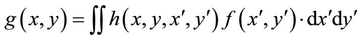
Generally, the radiation source image is obtained in the image plane through the thick pinhole. The intensity of the image plane could be given as:
 (1)
(1)
where:  is the corresponding intensity distribution at the image plane point (x, y) of the luminescence intensity f(x¢, y¢) at the object plane point (x¢, y¢) in accordance with the characteristics of the imaging system. Suppose the image plane intensity abides by the linear superposition, and according to the linear propagation principle, the image plane intensity could be obtained as the following:
 (2)
(2)
where:  is the response function of the object plane point (x¢, y¢) at the point (x, y) in the image plane with a supposed linear response between f(x¢, y¢) and h. Again, a certain hypothesis should be introduced to simplify the issue. First of all, suppose the thick pinhole imaging should be made in an ideal condition, with a static object plane and a static image plane, then Equation (2) could be expressed as follow:
 (3)
(3)
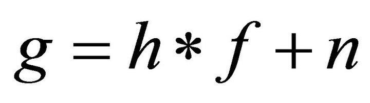
In the radiation imaging, the effects of the noise of the system have to be taken into consideration. Thus, the image plane intensity could be obtained in the following equation:
 (4)
(4)
where, n is the noise of the recording system.
2.2. The Point Spread Function (PSF) of the Thick Pinhole Image System
The point spread function (PSF) is a major characteristic parameter of the imaging system, standing for the intensity distribution of the infinitively small point light source after the pinhole imaging. However, since the point spread function (PSF) is very hard to measure in the actual tests, the simulation and computation results then could be used as an alternative. The computation of the point spread function (PSF) for the thick pinhole imaging system could be made with the geometry analytical method, and Monte Carlo N-Particle Transport Code (MCNP) neutron transportation program, etc. In the radiation imaging, due to the uniform spatial distribution of the secondary particles caused by various reactions between the neutrons and the thick pinhole shielding materials, the contribution of the secondary particles to the image detector could be negligible. Thus, in this paper, the geometry analytical method would be used for the computation of the point spread function (PSF) of the thick pinhole imaging system.
The basic principle of the pinhole imaging is given in Figure 1. The radiation source is imaged in the image plane (scintillator) through the thick pinhole. For every point in the image plane, its ray intensity is consisting with three sources: the particles straightly through the pinhole, the transmission particles partially through the pinhole and the transmission particles partially through the pinhole shielding. The ray intensity in the image plane could be given as follows:
 (5)
(5)
where: J(i, j) is the ray intensity of the point (i, j), L is the distance between the object plane and the image plane, s is Figure 1 the schematic diagram of the thick pinhole imaging the macro reactive cross section, T is the thickness of the pinhole shielding penetrated by the rays, and I is the ray intensity of image plane. Based on the principles mentioned above, the simulation program for the thick pinhole imaging was worked out to compute the point spread function (PSF) of the thick pinhole imaging system.
In the computation, the total thickness of the pinhole was 600 mm, the length of the straight aperture was 30 mm, the aperture size was 0.1 mm, the free path of the material was 7.5 mm, the image distance and the object
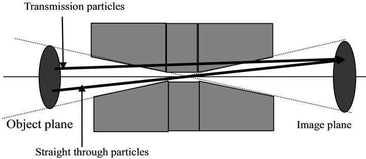
Figure 1. The schematic diagram of the thick pinhole imaging.
distance were both 2000 mm, and the top points of dualcone structures at the both ends were at the very center of the straight aperture to provide an optimized design for the thick pinhole. The simulated computational results of the distribution of the point spread function (PSF) of the thick pinhole imaging system are given in Figure 2.
In order to clarify the evolution of the intensity of the point spread function (PSF), the intensity distribution of the point spread function (PSF) nearby the axis was calculated, whose results are given in Figure 3. As indicated, the intensity nearby the effective field of view is sharply charged. And this is the major difference between the point spread function (PSF) of the thick pinhole imaging system with those of the other optical imaging systems.
3. The Super Resolution Processing Method of the Thick Pinhole Imaging
In the thick pinhole imaging system, the point spread function (PSF) of the system is variable with the change
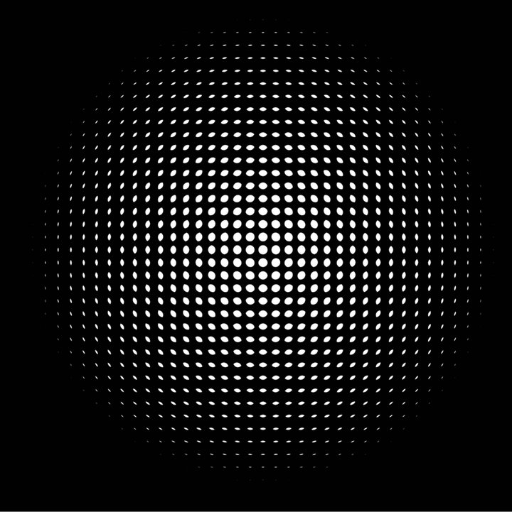
Figure 2. The schematic diagram of the distribution of the point spread function (PSF) within the field of view.
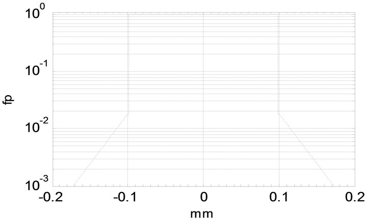
Figure 3. The schematic diagram of the distribution of the point spread function (PSF).
of the space. In dealing with the super resolution of the images with a determined point spread function (PSF) or single-frame image, Lucy-Richardson image super resolution processing method should be a very effective option. This method is characterized in a relatively big noise tolerance, which is deduced from iterative algorithm principle based on Bayesian posterior probability theory [6]. The specific calculation equation is given below:
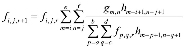 (6)
(6)
Besides, for the first estimation, the equation could then be expressed as:
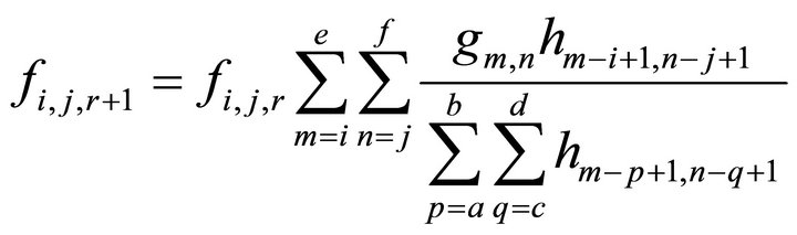 (7)
(7)
where: a = max(1, m − K + 1); b = min(m, I), c = max(1, n − L +1 ); d = min(n, J); e = I + K − 1; f = j + L − 1); I = 1, 2,∙∙∙I, j = 1, 2,∙∙∙J. Equation (6) requires a large quantity of computation. Thus, for simplification, only the point spread functions (PSF) within a limited area should be applied into the computation. In the case of the pinhole imaging, the point spread function (PSF) has a very sharp boundary, and the values of the pixels out of the boundary should be very small. In this sense, the selection of the radius of the point spread functions (PSF) should be made to provide the function values at the end of the radius far smaller than the peak values.
4. Simulation of the Thick Pinhole Imaging and the Image Super Resolution Image Reconstruction
4.1. Simulation of Thick Pinhole Image and Super Resolution Image Reconstruction of the Uniform Image
Again, Equation (6) requires a large quantity of iterative computation, and the required computation time is proportional to I2N4 (where: I is the image size and N is the size of the point spread function). As for the selection of I and N, both the image quality and the computation time should be carefully evaluated. In our computation, the pinhole diameter was 0.1 mm, the magnification was 1, the spatial resolution of the thick pinhole imaging system was 0.2 mm, and the pixel size in the image plane was 0.0088 mm/pixel. Finally, the computation of the ringtype pinhole imaging and image reconstruction were made, whose results are given in Figure 4. As indicated by the computational results, the spatial resolution of the thick pinhole imaging system could be increased by over three
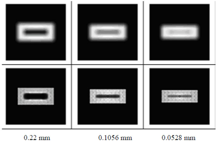
Figure 4. The uniform ring-type pinhole imaging and image reconstruction.
times after the image super resolution processing.
4.2. The Pinhole Image and Image Reconstruction of the Stepped Image
The thick pinhole is mainly used for the radiation source image diagnostics. Based on the above mentioned computational results, the simulation of the image distribution of the stepped shape was made, and a strip-type image was overlapped in the center of the image. The simulation and the image reconstruction were made to provide results in Figure 5. For both of the image reconstruction results, the 0.0088 mm-wide strip-type images could be reconstructed. However, for the stepped distribution, the 0.088 mm-wide step had better reconstruction results than that with 0.044 mm-wide step (hardly identified in the image but providing clarified intensity distribution). In this sense, it can be concluded that the method provides a fairly good image reconstruction results even for the complicated image reconstruction.
5. Noise Analysis of the Reconstructed Image
Throughout the above mentioned simulated thick pinhole imaging and image reconstruction, noise signals in plum blossom shape always occurred in the image reconstruction as shown in Figure 6. Such noise was especially strong in the center of the image with more visible distribution.
In order to identify the source of such noise, the simulated imaging with the ideal thin pinhole was introduced before image reconstruction to provide an ideal radiation source image as shown in Figure 7. Thus, the very source of the noise is caused by the thick pinhole structure.
For further insight, the thick pinhole imaging systems with magnifications of 1 and 10 respectively were used for the simulation of imaging and image reconstruction
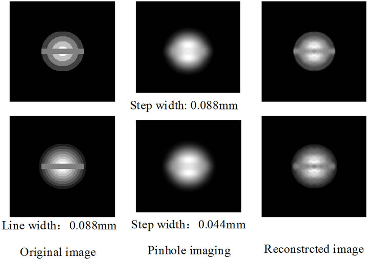
Figure 5. The pinhole imaging and image reconstruction of step distribution.
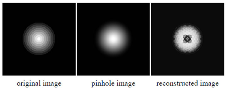
Figure 6. The schematic images of the noise in the reconstructed image of the thick pinhole.

Figure 7. The reconstructed images of the ideal thin and thick pinhole.
as shown in Figure 8. As indicated by the image reconstruction results, better image reconstruction results could be obtained with a bigger magnification. Again, it can be concluded that the image reconstruction results are related to the structure of the thick pinhole imaging system.
Then, two problems were found in the reconstruction of the gradient image. One is the reconstruction results is dependent on the magnification. The bigger the magnification is the better reconstruction results could be obtained. Another one is that the strongest noise signals occur nearby the axis of the pinhole. As indicated in Figure 9, in the straight aperture, the point spread function of the system is dependent on the back end, while outside the straight aperture, the point spread function is then dependent on both the back end and the front end. And the basic and major reason for the strongest noise nearby
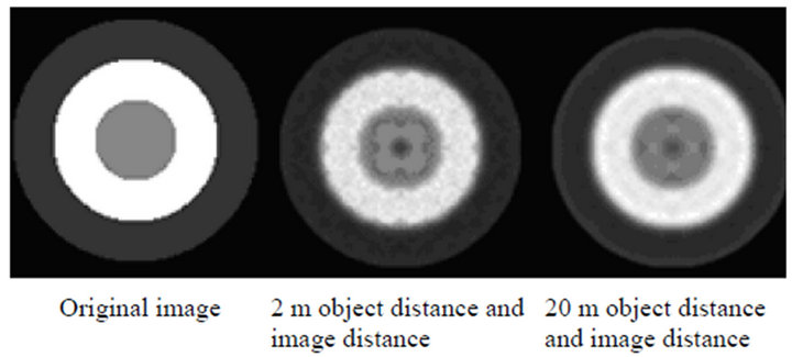
Figure 8. The effects of the various magnifications upon the image reconstruction.
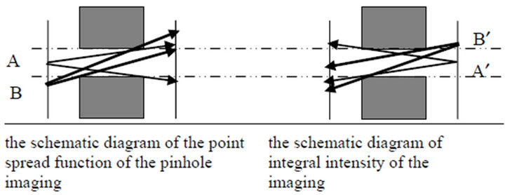
Figure 9. The schematic diagram of the image plane intensity nearby the axis of the thick pinhole.
the pinhole axis lies in the abrupt change of the point spread function nearby the straight aperture.
6. Conclusions
In the radiation image diagnostics, the thick pinhole imaging system is a major bottleneck to improve the spatial resolution of the image diagnostic system. Due to the continuous space-dependent variation of the spatial point spread function, the spatial domain method is the only option for the image super resolution reconstruction. With the introduction of the Lucy-Richardson method into the image reconstruction, the spatial resolution of the thick pinhole imaging system could be increased by over three times after the image super resolution processing.
In the image reconstruction, relatively strong noise would occur nearby the pinhole axis due to the image distortion nearby the straight aperture. Within view of the straight aperture, the point spread function is determined by the back end of the thick pinhole, while the expansion angel of the field of view of the object plane corresponding to the image plane is determined by the front end. As for the whole range of the field of view, the point spread function of the system is determined both by the front end and the back end of the thick pinhole. Besides, abrupt change of the point spread function takes place nearby the straight aperture.
Due to fact that the point spread function of the thick pinhole imaging system is determined both by the front end and the back end of the thick pinhole, with a relatively small image distance, the length of the thick pinhole could not be negligible. Comparatively, with a relatively big image distance, the length of the thick pinhole could be negligible and to provide reconstruction results approximately as good as those with the thin pinhole imaging system.
7. Acknowledgements
The study presented in this paper is jointly sponsored by both the Sci. & Tech. Development Foundation of China Academy of Engineering Physics (CAEP 2010B0103006 and CAEP 2011B0103017) and the National Natural Science Foundation of China (Grant No. 11005095). And the authors are also very thankful to associate professor Zhang Jianhua, associate professor Chen Jinchuan, Mr. Zhou Lin and other colleagues for their help during this study.
REFERENCES
- G. J. Yates and N. S. P. King, “High-Frame Intensified Fast Optically Shuttered TV Cameras with Selected Imaging Applications,” SPIE, Vol. 2273, 1997, pp. 126-149.
- J. C. Chen, “Typical Measurement Using Nanosecond Multi-Frame Camera on Angara-5-1 Joint Experiments,” Nuclear Electronics & Detection Technology, 2007, annual, pp. 46-51.
- C. R. Christensen, C. W. Bames, “First Result of Pinhole Neutron Imaging for Inertial Confinement Fusion,” Review of Scientific Instruments, Vol. 74, No. 5, 2003, pp. 2689-2694.
- X. W. Wang and Y. Liu, “Survey of Image Supper Resolution Investigation,” Information Technology, Vol. 7, 2009, pp. 236-240.
- M. Irani and S. Peleg, “Improving Resolution by Image Registion,” CVGIP, Vol. 53, No. 3, 1991, pp. 231-239.
- B. Wei and W. H. Hui, “POCS Embedded MAP Method for Image Super Resolution Restoration,” 4th IEEE Conference on Industrial Electronics and Applications, 2009, pp. 3791-3794.
- P. S. Wei, H. Y. Feng, “A New Method for Super-Resolution Reconstruction Using Wavelet Transform,” Proceedings of SPIE, Vol. 5985, 2005, pp. 1-5.
- H. Zhu and Y. Lu, “Super Resolution Image Restoration by Maximum Likelihood Method and Edge Orient Diffusion,” SPIE, Vol. 6625, 2008, pp. 1-8.
- W. Richardson, “Bayesian-Based Method of Image Restoration,” Journal of the Optical Society of America, Vol. 62, No. 1, 1972, pp. 55-59.
- E. N. Terentiev and N. E. Terentiev, “Super Resolution When PSF Is Indefinite,” Proceedings of SPIE, Vol. 4388, 2001, pp. 193-199.
- T. P. Costello and W. B. Mikhael, “Efficient Restoration of Space Variant Blurs from Physical Optics by Sectioning with Modified Wiener Filtering,” Digital Signal Processing, Vol. 13, No. 1, 2003, pp. 1-22.
- T. P. Costello and W. B. Mikhael, “Adaptively Fit, PasceVariant Point Spread Function Model for Spherical Lens Optical System,” Proceeding of the 1999 IEEE International Symposium on Circuits and System, Vol. 3, 1999. pp. 255-258.
NOTES
*Corresponding author.