Paper Menu >>
Journal Menu >>
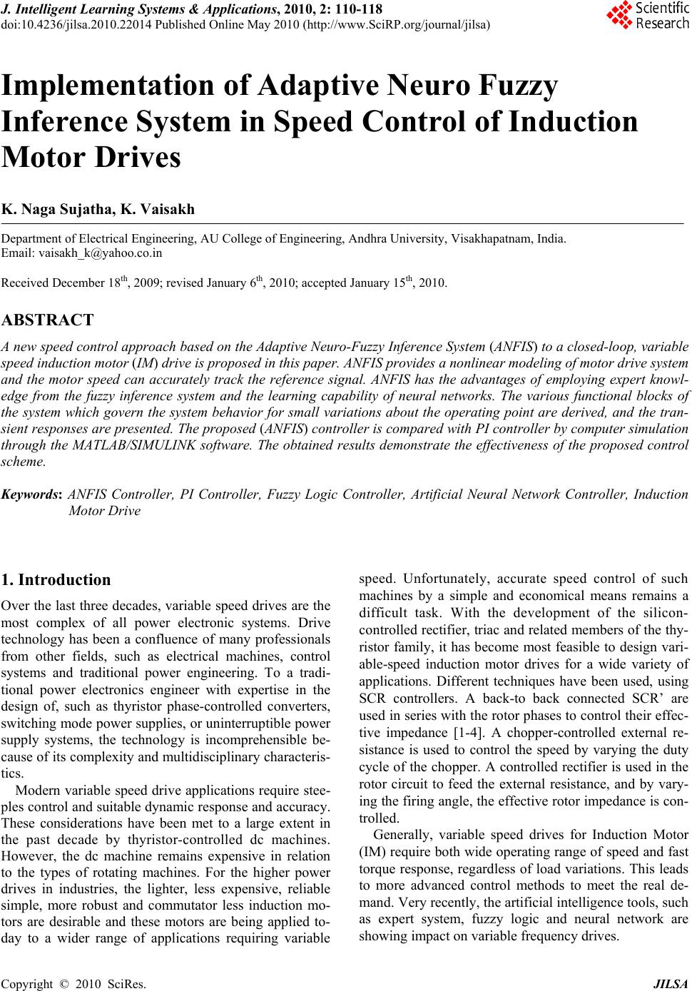 J. Intelligent Learning Systems & Applications, 2010, 2: 110-118 doi:10.4236/jilsa.2010.22014 Published Online May 2010 (http://www.SciRP.org/journal/jilsa) Copyright © 2010 SciRes. JILSA Implementation of Adaptive Neuro Fuzzy Inference System in Speed Control of Induction Motor Drives K. Naga Sujatha, K. Vaisakh Department of Electrical Engineering, AU College of Engineering, Andhra University, Visakhapatnam, India. Email: vaisakh_k@yahoo.co.in Received December 18th, 2009; revised January 6th, 2010; accepted January 15th, 2010. ABSTRACT A new speed control approach based on the Adaptive Neuro-Fuzzy Inference System (ANFIS) to a closed-loop, variable speed induction motor (IM) drive is proposed in this paper. ANFIS provides a nonlinear modeling of motor drive system and the motor speed can accurately track the reference signal. ANFIS has the advantages of employing expert knowl- edge from the fuzzy inference system and the learning capability of neural networks. The various functional blocks of the system which govern the system behavior for small variations about the operating point are derived, and the tran- sient responses are presented. The proposed (ANFIS) controller is compared with PI controller by computer simulation through the MATLAB/SIMULINK software. The obtained results demonstrate the effectiveness of the proposed control scheme. Keywords: ANFIS Controller, PI Controller, Fuzzy Logic Controller, Artificial Neural Network Controller, Induction Motor Drive 1. Introduction Over the last three decades, variable speed drives are the most complex of all power electronic systems. Drive technology has been a confluence of many professionals from other fields, such as electrical machines, control systems and traditional power engineering. To a tradi- tional power electronics engineer with expertise in the design of, such as thyristor phase-controlled converters, switching mode power supplies, or uninterruptible power supply systems, the technology is incomprehensible be- cause of its complexity and multidisciplinary characteris- tics. Modern variable speed drive applications require stee- ples control and suitable dynamic response and accuracy. These considerations have been met to a large extent in the past decade by thyristor-controlled dc machines. However, the dc machine remains expensive in relation to the types of rotating machines. For the higher power drives in industries, the lighter, less expensive, reliable simple, more robust and commutator less induction mo- tors are desirable and these motors are being applied to- day to a wider range of applications requiring variable speed. Unfortunately, accurate speed control of such machines by a simple and economical means remains a difficult task. With the development of the silicon- controlled rectifier, triac and related members of the thy- ristor family, it has become most feasible to design vari- able-speed induction motor drives for a wide variety of applications. Different techniques have been used, using SCR controllers. A back-to back connected SCR’ are used in series with the rotor phases to control their effec- tive impedance [1-4]. A chopper-controlled external re- sistance is used to control the speed by varying the duty cycle of the chopper. A controlled rectifier is used in the rotor circuit to feed the external resistance, and by vary- ing the firing angle, the effective rotor impedance is con- trolled. Generally, variable speed drives for Induction Motor (IM) require both wide operating range of speed and fast torque response, regardless of load variations. This leads to more advanced control methods to meet the real de- mand. Very recently, the artificial intelligence tools, such as expert system, fuzzy logic and neural network are showing impact on variable frequency drives.  Implementation of Adaptive Neuro Fuzzy Inference System in Speed Control of Induction Motor Drives111 They are applied to important fields such as variable speed drives, control systems, signal processing, and sys- tem modeling. Artificial Intelligent systems, means those systems that are capable of imitating the human reasoning process as well as handling quantitative and qualitative knowledge. It is well known that the intelligent systems, which can provide human like expertise such as domain knowledge, uncertain reasoning, and adaptation to a noisy and time-varying environment, are important in tackling practical computing problems. ANFIS has gain a lot of interest over the last few years as a powerful technique to solve many real world problems. Compared to conven- tional techniques, they own the capability of solving prob- lems that do not have algorithmic solution. Neural net- works and fuzzy logic technique are quite different, and yet with unique capabilities useful in information process- ing by specifying mathematical relationships among nu- merous variables in a complex system, performing map- pings with degree of imprecision, control of nonlinear system to a degree not possible with conventional linear systems [5-11]. To overcome the drawbacks of Neural networks and fuzzy logic, Adaptive Neuro-Fuzzy Infer- ence System (ANFIS) was proposed in this paper. The ANFIS is, from the topology point of view, an implemen- tation of a representative fuzzy inference system using a Back Propagation neural network structure. The purpose of this paper is to present a general method for estimating both the nature of the dynamic response and the values of the significant parameters and operating constraints of typical induction machines con- trolled by SCR controllers [12,13]. The dynamic behav- ior of a closed-loop speed-control system with delta- connected SCR’s in the rotor is discussed. The various functional blocks of the feedback system which governs the system behavior for small variations about the oper- ating point are derived, and responses for speed perturba- tions are obtained analytically and simulated. 2. State Space Approach A Set of nonlinear differential equations can describe the behavior of the induction motor [14-16]. If a complete solution of the dynamic behavior of the induction ma- chine is desired, these equations must be solved in detail. By linerarizing these questions about a steady state oper- ating condition, the resulting equations in state form can describe the dynamics, and provide the future state and output of the system. Perturbations in reference voltage or firing angle and load torque leads to changes in rotor speed. The analyti- cal results used to investigate these speed changes are obtained considering the various previous functional blocks, where the different input and output variables are denoted by X1, X2, X3 and X4. These variables are defined as follows: X1 = , X2 = V, X3= Vc and X4 = (1) The differential equations, which govern the small variations about the operating point, are written in terms of the above variables and representing in matrix form in Equation (2), where 1234 T X xx xx , = T LR uTV 12 T uu 3. System Description The system consists of a slip-ring induction motor with three equal external resistances, each connected to the rotor phase and three delta-connected phase-controlled SCR's placed at the open star point of the rotor as shown in Figure 1. In variable speed ac induction motor drives, a con- tinuous monitoring or control of slip speed or slip fre- quency is required. A permanent magnet tachogenerator is mounted on the rotor shaft to provide a dc signal pro- portional to the rotor speed to the feedback control cir- cuit. The block diagram of the feedback control scheme of the induction motor is shown in Figure 2. The induction motor stator is supplied with constant voltage, constant frequency supply. The rotor speed is controlled and adjusted by advancing or retarding the firing angle of the SCRs. The tachogenerator output voltage proportional to the rotor speed and is compared 54 1 1 1 11 2 2 33 2 122 2 2 4 4 121 3 33 100 0 100 00 0 00 00 1 00 GG GGG G G L R KK KK TTT K T xx K TT x xT x x K KKK K T xx TTT K TT V (2) Copyright © 2010 SciRes. JILSA  Implementation of Adaptive Neuro Fuzzy Inference System in Speed Control of Induction Motor Drives 112 3 Phase Supply To Trigger Circuit Rex a T1 Rex Figure 1. Schematic diagram of phase controlled SCR’s in delta (Δ) configuration Figure 2. Block diagram of feedback system with a fixed dc level R V which represents the set speed. The error voltage is forwarded to the controller. The set peed is changed by varying R V automatically or manu- ally. The controller may be a proportional, or propor- tional integral or proportional integral derivation type. The function of the controller is to give the required con- trol voltage which will adjust the firing angle to the suit- able value and can be used also as a stabilizing signal if more than one controller is used. The simulink block diagram of feedback control scheme of the induction motor is shown in Figure 3. Transfer functions for the functional blocks: The transfer functions for the various functions blocks of the feedback system are shown in Figure 4, and given in details as follows: 1) Tachogenerator and filter: The transfer function of this block is represented by: 1 1 1 1 K Gs ST (3) where 1 K is the combined gain of the tachogenerator and the associated filter, and is the effective time constant of the filter. 1 T 2) Controller: The change in the output voltage of the tachogenerator is compared with the reference voltage R V and the resultant error voltage is fed to the controller. The controller output voltage is corrected in accordance with the input change in voltage. The change in the con- troller output voltage is denoted as . The transfer function of the proportional integral controller is: c V 2 1 2 (1 ) 2 K ST Gs ST (4) 3) Firing Circuit: The firing circuit decides the change in firing angle in accordance with the change in control voltage . It consists of a ramp generator and a com- parator. The ramp is synchronized with the signal avail- able across the slip-rings of the machine. For a given change in the control voltage , the change in firing angle is given by: c V c V 1 c V m (5) where m is the slope of the ramp. For the present study, the firing circuit transfer function can be written as 3 3 3 1 K Gs ST (6) where 3 K is equal to l/m, and the time constant is equal to one half of the maximum expected delay. If the slip of the rotor at the operating point is s, then the time constant is given by: 3 T 3 1 23 Tsf (7) c T2 b Rex T3 _ TACHO GENERATOR REF.VOLTAGE SLIP RING ROTOR + ERROR SIGNAL CONTROL VOLTAGE c V SLIP RING I.M DELTA CONNECTED SCR’s FIRING CIRCUIT P/PI/PID CONTROLLER “ ” FIRING ANGLE R V 3-PHASE SUPPLY Copyright © 2010 SciRes. JILSA  Implementation of Adaptive Neuro Fuzzy Inference System in Speed Control of Induction Motor Drives JILSA 113 Figure 3. The simulink block diagram of feedback control scheme of the induction motor drive Figure 4. Functional blocks of closed-loop system 4) Induction Motor: The torque developed by the ma- chine at a given operating point is a function of speed of the machine and the firing angle of the thyristors. The difference between the developed torque and the load torque is applied to the rotating elements. The torque developed by the machine is presented by (,) d TF (8) where is the rotor speed in rad/sec, and is the firing angle. For the dynamic behavior of the induction machine about any operating point for a given perturbation, the small change in the developed torque can be represented in terms of the small changes in rotor speed and firing angle as: tan tan d d d T T Tcons t cons t (9) or 45d TK K (10) The constants 4 K and 5 K depend upon the operat- ing point and are to be obtained from the steady-state characteristics of the system. The resultant change in the developed torque is repre- sented as the summation of the outputs of the two blocks (4) and (5). The change in the developed torque is com- pared with the change in load torque and the resultant value is forwarded to the mechanical system, whose transfer function can be expressed as: 1 G m G K Gs ST (11) where G K = 1 F and = G T J F (6) (5) (4) (2) (3) d T _ + R V SPEED CHARACT. I.M.TECH T _ ELECTRICAL TORQUE “ ” FIRING ANGLE c V ERROR SIGNAL 22 2 (1 ) K ST ST 3 3 1 K ST 4 d c T K 5 d c T K 1 G G K ST 1 1 1 K ST + L T + (1) -K -K Switch S1 Sco p e - Gain Gain - + PI Controller ANFIS Con- troller Without any controller Transfer Function + Transfer Function Transfer Function Step Ste p + Copyright © 2010 SciRes. 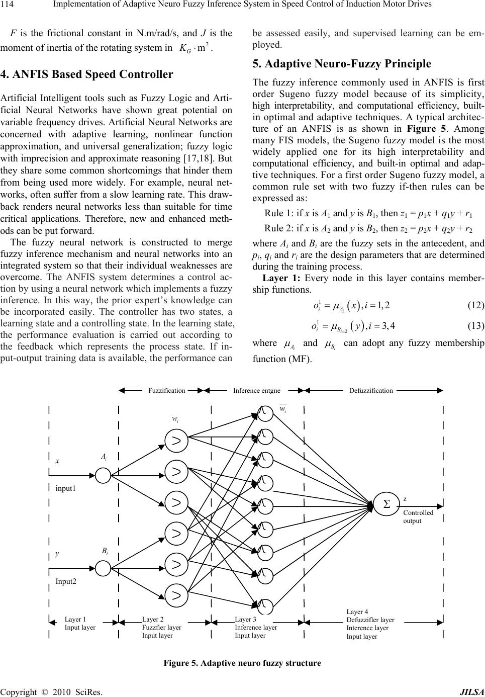 Implementation of Adaptive Neuro Fuzzy Inference System in Speed Control of Induction Motor Drives 114 F is the frictional constant in N.m/rad/s, and J is the moment of inertia of the rotating system in 2 m G K . 4. ANFIS Based Speed Controller Artificial Intelligent tools such as Fuzzy Logic and Arti- ficial Neural Networks have shown great potential on variable frequency drives. Artificial Neural Networks are concerned with adaptive learning, nonlinear function approximation, and universal generalization; fuzzy logic with imprecision and approximate reasoning [17,18]. But they share some common shortcomings that hinder them from being used more widely. For example, neural net- works, often suffer from a slow learning rate. This draw- back renders neural networks less than suitable for time critical applications. Therefore, new and enhanced meth- ods can be put forward. The fuzzy neural network is constructed to merge fuzzy inference mechanism and neural networks into an integrated system so that their individual weaknesses are overcome. The ANFIS system determines a control ac- tion by using a neural network which implements a fuzzy inference. In this way, the prior expert’s knowledge can be incorporated easily. The controller has two states, a learning state and a controlling state. In the learning state, the performance evaluation is carried out according to the feedback which represents the process state. If in- put-output training data is available, the performance can be assessed easily, and supervised learning can be em- ployed. 5. Adaptive Neuro-Fuzzy Principle The fuzzy inference commonly used in ANFIS is first order Sugeno fuzzy model because of its simplicity, high interpretability, and computational efficiency, built- in optimal and adaptive techniques. A typical architec- ture of an ANFIS is as shown in Figure 5. Among many FIS models, the Sugeno fuzzy model is the most widely applied one for its high interpretability and computational efficiency, and built-in optimal and adap- tive techniques. For a first order Sugeno fuzzy model, a common rule set with two fuzzy if-then rules can be expressed as: Rule 1: if x is A1 and y is B1, then z1 = p1x + q1y + r1 Rule 2: if x is A2 and y is B2, then z2 = p2x + q2y + r2 where Ai and Bi are the fuzzy sets in the antecedent, and pi, qi and ri are the design parameters that are determined during the training process. Layer 1: Every node in this layer contains member- ship functions. 1,1,2 i iA oxi (12) 2 1,3,4 i iB oyi (13) where i A and i B can adopt any fuzzy membership function (MF). Figure 5. Adaptive neuro fuzzy structure z Controlled output y Input2 x input1 Fuzzification Inference entgne Defuzzification Layer 1 Input layer i w i i w i A B Layer 2 Fuzzfier layer Input layer Layer 3 Inference layer Input layer Layer 4 Defuzzifler layer Interence layer Input layer Copyright © 2010 SciRes. JILSA  Implementation of Adaptive Neuro Fuzzy Inference System in Speed Control of Induction Motor Drives115 Layer 2: This layer chooses the minimum value of two input weights. 2,1,2 ii iiA B owx yi (14) Layer 3: Every node of these layers calculates the weight, which is normalized. 3 12 ,1,2 i ii w ow i ww (15) where i w is referred to as the normalized firing strengths. Layer 4: This layer includes linear functions, which are functions of the input signals. 4(), iiiiiii owzwpxqyri 1,2 (16) where i w is the output of layer 3, and {pi, qi, ri} is the parameter set. The parameters in this layer are referred to as the consequent parameters. Layer 5: This layer sums all the incoming signals. 2 51122 112 iii i wz wz owz ww (17) The output z in Figure 5 can be rewritten as: 11 11 11 22 22 2 zwxp wyqwr wxp wyq wr 2 (18) In this paper the normalized membership functions of input variables and output variable are shown in Figures 6 and 7. The Three-dimensional plot of Fuzzy Control surface is shown in Figure 8. 6. Simulation Results In this paper, performance of the proposed ANFIS speed controller is evaluated and is compared with PI controller and without any controller. The controller parameters are chosen to optimize the performance criterion of the dy- namic operation, and then the tuning was empirically improved. The simulation is carried out to observe the performance of the system at different load perturbations. Figure 6. Triangular membership functions for input variables e and e Figure 7. Triangular membership functions for output variable Figure 8. Three-dimensional plot of control surface The software environment used for this simulation is Matlab ver. 7.1, with simulink package. The change in rotor speed is due to the perturbations in reference voltage or firing angle and load torque. The analytical results used to investigate these speed changes are obtained considering the various previous functional blocks, where the different input and output variables are denoted by X1, X2, X3 & X4. The differential equations which govern the small variations about the operating point in terms of above variables are given in Equation (2). The perturbation studies were carried out at different operating points with different system parameters (gains and time constants) which are given in Appendix. Studies are carried out at operating points with various system parameters (gains and time constants). The simulation results give the present perturbation study for step change in the load torque and reference voltage. From the Figures 9 to 11 the starting transients are realized for ANFIS controller at different operating conditions. It can be observed from the figures that the performance of the ANFIS gives better response compared with PI controller and without any controller. 7. Conclusions A framework for tuning and self organizing ANFIS con- troller has been presented. This approach has been con- Copyright © 2010 SciRes. JILSA 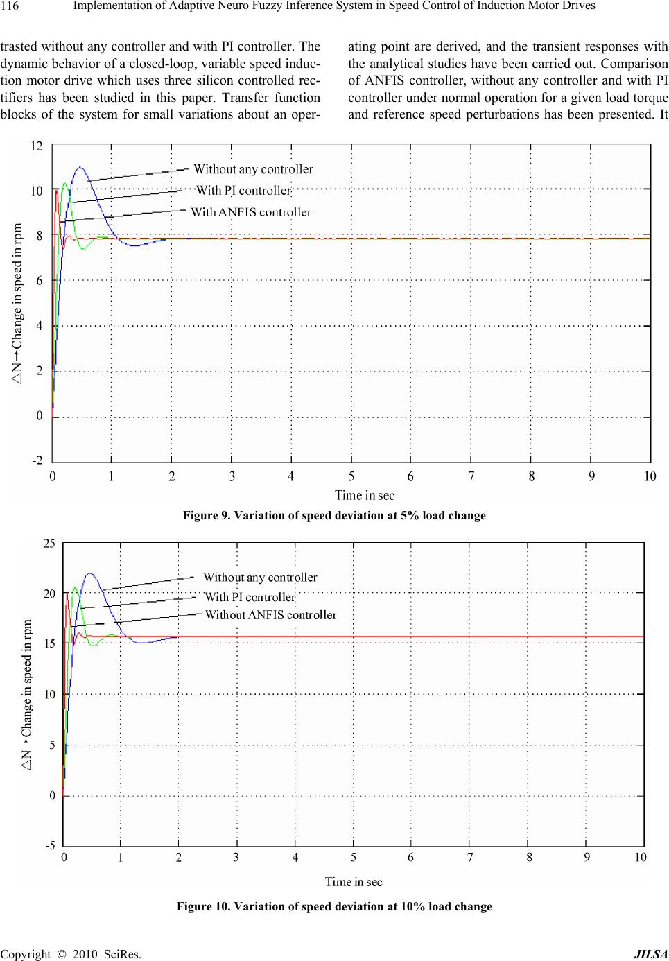 Implementation of Adaptive Neuro Fuzzy Inference System in Speed Control of Induction Motor Drives 116 trasted without any controller and with PI controller. The dynamic behavior of a closed-loop, variable speed induc- tion motor drive which uses three silicon controlled rec- tifiers has been studied in this paper. Transfer function blocks of the system for small variations about an oper- ating point are derived, and the transient responses with the analytical studies have been carried out. Comparison of ANFIS controller, without any controller and with PI controller under normal operation for a given load torque and reference speed perturbations has been presented. It Figure 9. Variation of speed deviation at 5% load change Figure 10. Variation of speed deviation at 10% load change Copyright © 2010 SciRes. JILSA 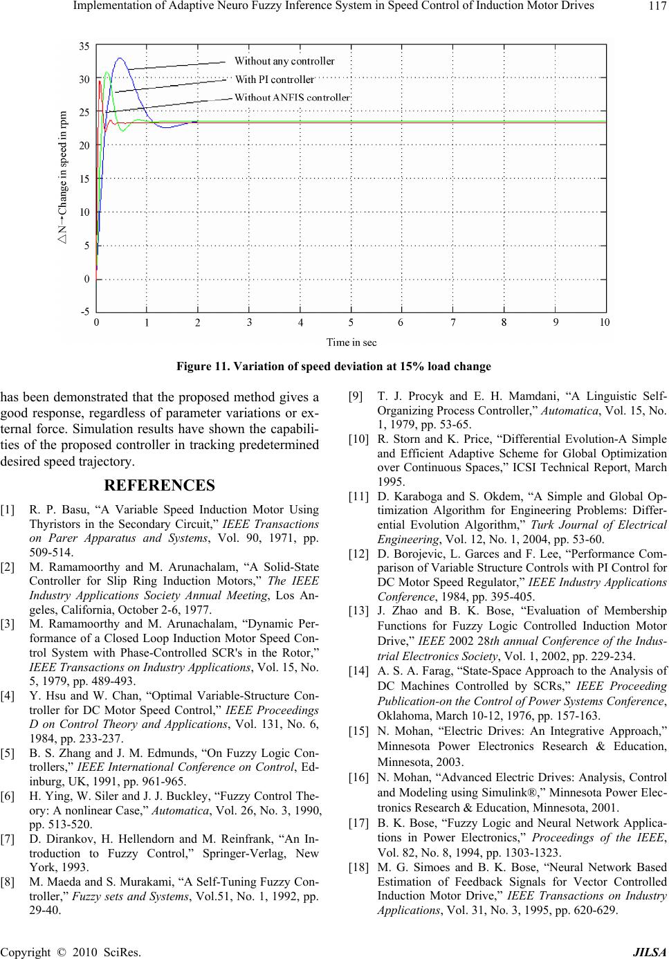 Implementation of Adaptive Neuro Fuzzy Inference System in Speed Control of Induction Motor Drives117 Figure 11. Variation of speed deviation at 15% load change has been demonstrated that the proposed method gives a good response, regardless of parameter variations or ex- ternal force. Simulation results have shown the capabili- ties of the proposed controller in tracking predetermined desired speed trajectory. REFERENCES [1] R. P. Basu, “A Variable Speed Induction Motor Using Thyristors in the Secondary Circuit,” IEEE Transactions on Parer Apparatus and Systems, Vol. 90, 1971, pp. 509-514. [2] M. Ramamoorthy and M. Arunachalam, “A Solid-State Controller for Slip Ring Induction Motors,” The IEEE Industry Applications Society Annual Meeting, Los An- geles, California, October 2-6, 1977. [3] M. Ramamoorthy and M. Arunachalam, “Dynamic Per- formance of a Closed Loop Induction Motor Speed Con- trol System with Phase-Controlled SCR's in the Rotor,” IEEE Transactions on Industry Applications, Vol. 15, No. 5, 1979, pp. 489-493. [4] Y. Hsu and W. Chan, “Optimal Variable-Structure Con- troller for DC Motor Speed Control,” IEEE Proceedings D on Control Theory and Applications, Vol. 131, No. 6, 1984, pp. 233-237. [5] B. S. Zhang and J. M. Edmunds, “On Fuzzy Logic Con- trollers,” IEEE International Conference on Control, Ed- inburg, UK, 1991, pp. 961-965. [6] H. Ying, W. Siler and J. J. Buckley, “Fuzzy Control The- ory: A nonlinear Case,” Automatica, Vol. 26, No. 3, 1990, pp. 513-520. [7] D. Dirankov, H. Hellendorn and M. Reinfrank, “An In- troduction to Fuzzy Control,” Springer-Verlag, New York, 1993. [8] M. Maeda and S. Murakami, “A Self-Tuning Fuzzy Con- troller,” Fuzzy sets and Systems, Vol.51, No. 1, 1992, pp. 29-40. [9] T. J. Procyk and E. H. Mamdani, “A Linguistic Self- Organizing Process Controller,” Automatica, Vol. 15, No. 1, 1979, pp. 53-65. [10] R. Storn and K. Price, “Differential Evolution-A Simple and Efficient Adaptive Scheme for Global Optimization over Continuous Spaces,” ICSI Technical Report, March 1995. [11] D. Karaboga and S. Okdem, “A Simple and Global Op- timization Algorithm for Engineering Problems: Differ- ential Evolution Algorithm,” Turk Journal of Electrical Engineering, Vol. 12, No. 1, 2004, pp. 53-60. [12] D. Borojevic, L. Garces and F. Lee, “Performance Com- parison of Variable Structure Controls with PI Control for DC Motor Speed Regulator,” IEEE Industry Applications Conference, 1984, pp. 395-405. [13] J. Zhao and B. K. Bose, “Evaluation of Membership Functions for Fuzzy Logic Controlled Induction Motor Drive,” IEEE 2002 28th annual Conference of the Indus- trial Electronics Society, Vol. 1, 2002, pp. 229-234. [14] A. S. A. Farag, “State-Space Approach to the Analysis of DC Machines Controlled by SCRs,” IEEE Proceeding Publication-on the Control of Power Systems Conference, Oklahoma, March 10-12, 1976, pp. 157-163. [15] N. Mohan, “Electric Drives: An Integrative Approach,” Minnesota Power Electronics Research & Education, Minnesota, 2003. [16] N. Mohan, “Advanced Electric Drives: Analysis, Control and Modeling using Simulink®,” Minnesota Power Elec- tronics Research & Education, Minnesota, 2001. [17] B. K. Bose, “Fuzzy Logic and Neural Network Applica- tions in Power Electronics,” Proceedings of the IEEE, Vol. 82, No. 8, 1994, pp. 1303-1323. [18] M. G. Simoes and B. K. Bose, “Neural Network Based Estimation of Feedback Signals for Vector Controlled Induction Motor Drive,” IEEE Transactions on Industry Applications, Vol. 31, No. 3, 1995, pp. 620-629. Copyright © 2010 SciRes. JILSA  Implementation of Adaptive Neuro Fuzzy Inference System in Speed Control of Induction Motor Drives 118 Appendix Various Gains and Time Constants used for Perturbation Study (Motor Speed 'N = 1050 rpm) K1 = 0.032 K2 = 0.25 K3 = –60 K4 = –0.0363 K5 = 40.0 T1 = 0.009 T2 = 0.22 T3 = 0.01111 K5 = –0.095 TG = 15.6 Copyright © 2010 SciRes. JILSA |