 Journal of Transportation Technologies, 2012, 2, 129-143 http://dx.doi.org/10.4236/jtts.2012.22014 Published Online April 2012 (http://www.SciRP.org/journal/jtts) Modeling of Energy Processes in Wheel-Rail Contacts Operating under Influence of Periodic Discontinuous Forces Zdzislaw Trzaska Department of Management, Warsaw University of Ecology and Managemenet, Warsaw, Poland Email: zdzislaw.trzaska@netlandia.pl Received December 16, 2011; revised January 22, 2012; accepted February 24, 2012 ABSTRACT In this paper we present new numerical simulation approaches for determining the energy processes under periodic conditions caused by time-discontinuous forces in the wheel-rail contacts. The main advantage of the presented method is the total elimination of frequency analysis, which in effect introduces important simplifications in the identification of the effects in the contact. The second important feature is the fact that the method is based on the analysis of appropriate loops on the energy phase plane leading to an easy estimation of the rail strength through the evaluation of the loop’s area. That model based simulation in the applied dynamics relies on advanced methods for model setup, robust and ef- ficient numerical solution techniques and powerful simulation tools for practical applications. Fundamental properties of contact displacements of the rail surface have been considered on the basis of the newly established method. The contact zone between railway wheels and the rail surfaces made of bulk materials is perceived as strong enough to re- sist the normal (vertical) forces introduced by heavy loads and the dynamic response induced by track and wheel ir- regularities. The analysis is carried out for a wheel running on an elastic rail rested on sleepers arranged on completely rigid foundation. The equations of displacement motion are established through the application of the Lagrange equa- tions approach. The established model of the wheel-rail contact dynamics has been applied to that same roll plane but with taking into account a nonlinear characteristic of the sleeper with respect to the ground. Attention then is focused completely on the modeling of the energy absorbed by the rail. The applied method employs the energy state variables as time functions leading to determine the susceptibility of a given contact on the strength induced by the rail roll. Keywords: Wheel-Rail Contact; Energy Process; Periodic Discontinuous Force; One-Period Energy; Energy Loop 1. Introduction In the analysis of wheel-rail contact several modeling methods can be applied and in the course of the last dec- ade new demands have emerged. They are mainly con- nected with the reduction of costs of maintenance, tech- nical diagnostics of the track and of railway vehicles, and elimination of negative effects on the environment. Many of the works have been related to the increase in train speed of railway vehicles without affecting safety and comfort [1-6]. Recently, the advanced technology is confronted in- creasingly with damping problems that do not address to issues of scaling. The contact zone (roughly 1 cm2) be- tween a railway wheel and rail is small compared with their overall dimensions and its shape depends not only on the rail and wheel geometry but also on how the wheel meets the rail influence. Thus, studying the com- plex motions of railway vehicles could give significant new insight into the defect properties of materials—a research domain where relatively little first-principles progress has been made. A hard problem arises when the wheel-rail contact is subject to an action of time-discontinuous forces. It is well known that in the contact zone between railway wheel and rail the surfaces and bulk material must be strong enough to resist the normal (vertical) forces in- troduced by heavy loads and the dynamic response in- duced by track and wheel irregularities. Thus, the inter- actions of the surface and the volume of a solid rail are important. It is not possible to materials grow without dislocations and/or other disturbances to crystalline order, such as vacancies, interstitials, or substitution impurities. In the case of polycrystalline materials, the memory fea- tures of hysteresis may be important according to the methods of their fabrication. Long before defects escalate to the point of incipient failure, they still influence vibra- tions. In its simplest form the equations of dynamic mo- tion of a wheel-rail system are given by a non-linear C opyright © 2012 SciRes. JTTs 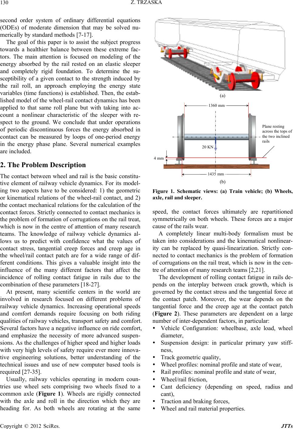 Z. TRZASKA 130 second order system of ordinary differential equations (ODEs) of moderate dimension that may be solved nu- merically by standard methods [7-17]. The goal of this paper is to assist the subject progress towards a healthier balance between these extreme fac- tors. The main attention is focused on modeling of the energy absorbed by the rail rested on an elastic sleeper and completely rigid foundation. To determine the su- sceptibility of a given contact to the strength induced by the rail roll, an approach employing the energy state variables (time functions) is established. Then, the estab- lished model of the wheel-rail contact dynamics has been applied to that same roll plane but with taking into ac- count a nonlinear characteristic of the sleeper with re- spect to the ground. We conclude that under operations of periodic discontinuous forces the energy absorbed in contact can be measured by loops of one-period energy in the energy phase plane. Several numerical examples are included. 2. The Problem Description The contact between wheel and rail is the basic constitu- tive element of railway vehicle dynamics. For its model- ing two aspects have to be considered: 1) the geometric or kinematical relations of the wheel-rail contact, and 2) the contact mechanical relations for the calculation of the contact forces. Strictly connected to contact mechanics is the problem of formation of corrugations on the rail treat, which is now in the centre of attention of many research teams. The knowledge of railway vehicle dynamics al- lows us to predict with confidence what the values of contact stress, tangential creep forces and creep age in the wheel/rail contact patch are for a wide range of dif- ferent conditions. This gives a valuable insight into the influence of the many different factors that affect the incidence of rolling contact fatigue in rails due to the combination of these parameters [18-27]. At present, many scientific centers in the world are involved in research focused on different problems of railway vehicle dynamics. Increasing operational speeds and comfort demands require focusing on both riding qualities of railway vehicles, transport safety and comfort. Several factors have a negative influence on ride comfort, and emphasize the necessity of more advanced suspen- sions. As the challenges of higher speed and higher loads with very high levels of safety require ever more innova- tive engineering solutions, better understanding of the technical issues and use of new computer based tools is required [27-35]. Usually, railway vehicles operating in modern coun- tries use wheel sets comprising two wheels fixed to a common axle (Figure 1). Wheels are rigidly connected with the axle and roll in the direction which they are heading for. As both wheels are rotating at the same (a) b) 1360 mm 20 KN 4 mm 1435 mm Plane resting across the tops o the two inclined rails (b) Figure 1. Schematic views: (a) Train vehicle; (b) Wheels, axle, rail and sleeper. speed, the contact forces ultimately are repartitioned symmetrically on both wheels. These forces are a major cause of the rails wear. A completely linear multi-body formalism must be taken into considerations and the kinematical nonlinear- ity can be replaced by quasi-linearization. Strictly con- nected to contact mechanics is the problem of formation of corrugations on the rail treat, which is now in the cen- tre of attention of many research teams [2,21]. The development of rolling contact fatigue in rails de- pends on the interplay between crack growth, which is governed by the contact stress and the tangential force at the contact patch. Moreover, the wear depends on the tangential force and the creep age at the contact patch (Figure 2). These parameters are dependent on a large number of inter-dependent factors, in particular: Vehicle Configuration: wheelbase, axle load, wheel diameter, Suspension design: in particular primary yaw stiff- ness, Track geometric quality, Wheel profiles: nominal profile and state of wear, Rail profiles: nominal profile and state of wear, Wheel/rail friction, Cant deficiency (depending on speed, radius and cant), Traction and braking forces, Wheel and rail material properties. Copyright © 2012 SciRes. JTTs 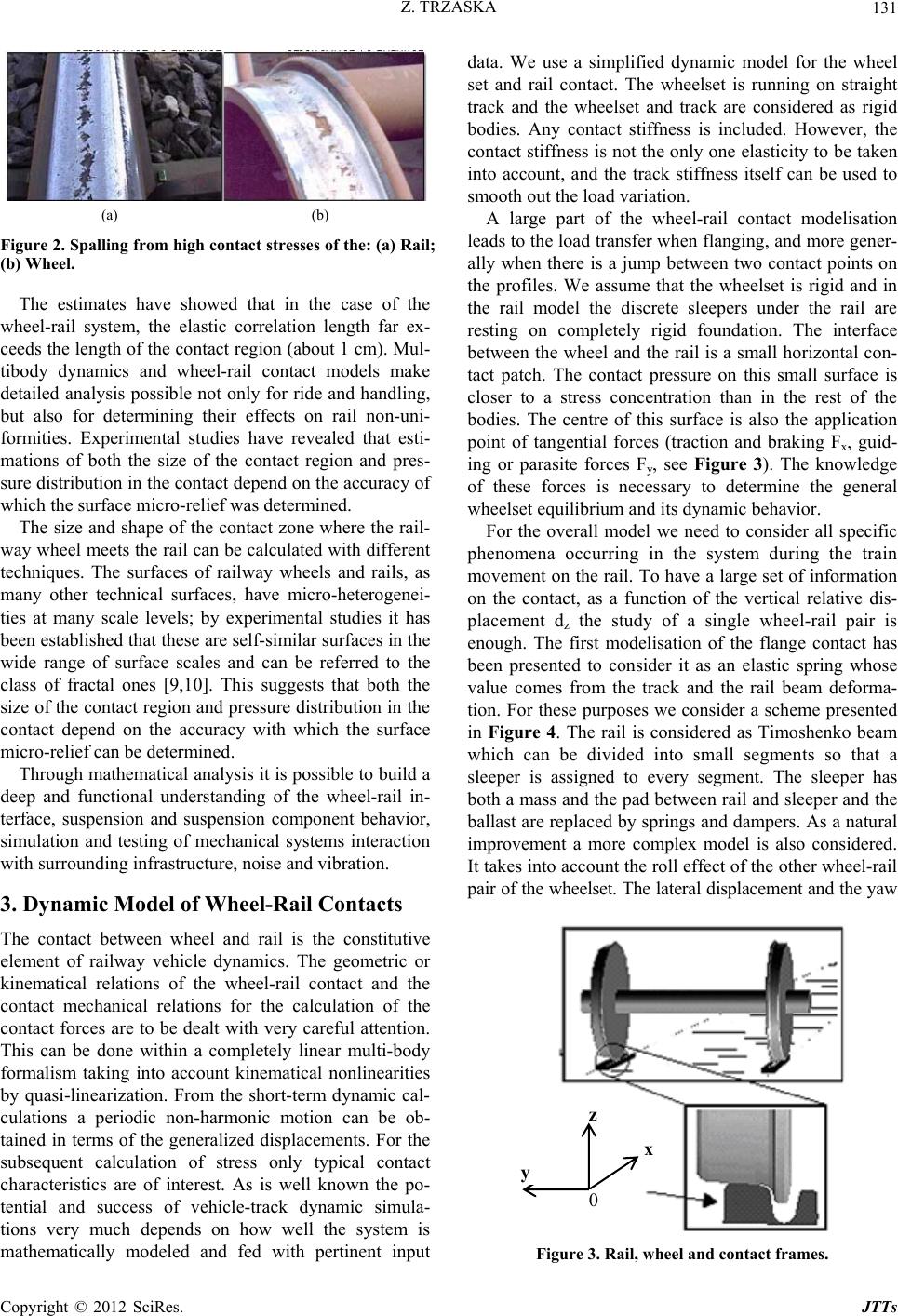 Z. TRZASKA 131 (a) (b) Figure 2. Spalling from high contact stresses of the: (a) Rail; (b) Wheel. The estimates have showed that in the case of the wheel-rail system, the elastic correlation length far ex- ceeds the length of the contact region (about 1 cm). Mul- tibody dynamics and wheel-rail contact models make detailed analysis possible not only for ride and handling, but also for determining their effects on rail non-uni- formities. Experimental studies have revealed that esti- mations of both the size of the contact region and pres- sure distribution in the contact depend on the accuracy of which the surface micro-relief was determined. The size and shape of the contact zone where the rail- way wheel meets the rail can be calculated with different techniques. The surfaces of railway wheels and rails, as many other technical surfaces, have micro-heterogenei- ties at many scale levels; by experimental studies it has been established that these are self-similar surfaces in the wide range of surface scales and can be referred to the class of fractal ones [9,10]. This suggests that both the size of the contact region and pressure distribution in the contact depend on the accuracy with which the surface micro-relief can be determined. Through mathematical analysis it is possible to build a deep and functional understanding of the wheel-rail in- terface, suspension and suspension component behavior, simulation and testing of mechanical systems interaction with surrounding infrastructure, noise and vibration. 3. Dynamic Model of Wheel-Rail Contacts The contact between wheel and rail is the constitutive element of railway vehicle dynamics. The geometric or kinematical relations of the wheel-rail contact and the contact mechanical relations for the calculation of the contact forces are to be dealt with very careful attention. This can be done within a completely linear multi-body formalism taking into account kinematical nonlinearities by quasi-linearization. From the short-term dynamic cal- culations a periodic non-harmonic motion can be ob- tained in terms of the generalized displacements. For the subsequent calculation of stress only typical contact characteristics are of interest. As is well known the po- tential and success of vehicle-track dynamic simula- tions very much depends on how well the system is mathematically modeled and fed with pertinent input data. We use a simplified dynamic model for the wheel set and rail contact. The wheelset is running on straight track and the wheelset and track are considered as rigid bodies. Any contact stiffness is included. However, the contact stiffness is not the only one elasticity to be taken into account, and the track stiffness itself can be used to smooth out the load variation. A large part of the wheel-rail contact modelisation leads to the load transfer when flanging, and more gener- ally when there is a jump between two contact points on the profiles. We assume that the wheelset is rigid and in the rail model the discrete sleepers under the rail are resting on completely rigid foundation. The interface between the wheel and the rail is a small horizontal con- tact patch. The contact pressure on this small surface is closer to a stress concentration than in the rest of the bodies. The centre of this surface is also the application point of tangential forces (traction and braking Fx, guid- ing or parasite forces Fy, see Figure 3). The knowledge of these forces is necessary to determine the general wheelset equilibrium and its dynamic behavior. For the overall model we need to consider all specific phenomena occurring in the system during the train movement on the rail. To have a large set of information on the contact, as a function of the vertical relative dis- placement dz the study of a single wheel-rail pair is enough. The first modelisation of the flange contact has been presented to consider it as an elastic spring whose value comes from the track and the rail beam deforma- tion. For these purposes we consider a scheme presented in Figure 4. The rail is considered as Timoshenko beam which can be divided into small segments so that a sleeper is assigned to every segment. The sleeper has both a mass and the pad between rail and sleeper and the ballast are replaced by springs and dampers. As a natural improvement a more complex model is also considered. It takes into account the roll effect of the other wheel-rail pair of the wheelset. The lateral displacement and the yaw x z y 0 Figure 3. Rail, wheel and contact frames. Copyright © 2012 SciRes. JTTs 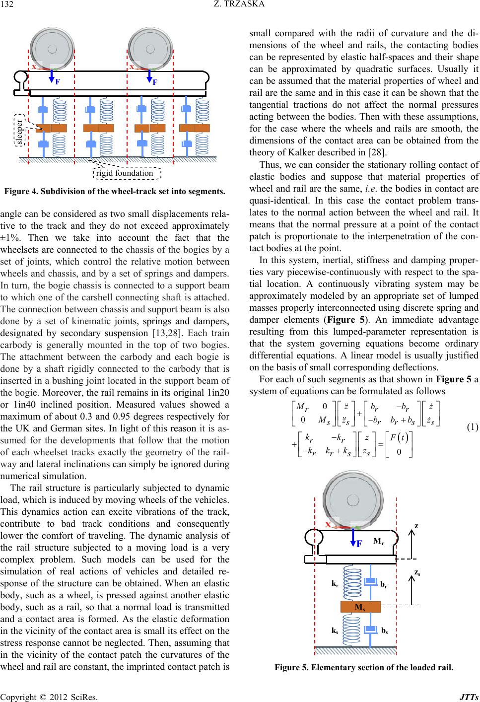 Z. TRZASKA 132 sleepe rigid foundation F F Figure 4. Subdivision of the wheel-tr a c k se t into se gments. angle can be considered as two small displacements rela- tive to the track and they do not exceed approximately ±1%. Then we take into account the fact that the wheelsets are connected to the chassis of the bogies by a set of joints, which control the relative motion between wheels and chassis, and by a set of springs and dampers. In turn, the bogie chassis is connected to a support beam to which one of the carshell connecting shaft is attached. The connection between chassis and support beam is also done by a set of kinematic joints, springs and dampers, designated by secondary suspension [13,28]. Each train carbody is generally mounted in the top of two bogies. The attachment between the carbody and each bogie is done by a shaft rigidly connected to the carbody that is inserted in a bushing joint located in the support beam of the bogie. Moreover, the rail remains in its original 1in20 or 1in40 inclined position. Measured values showed a maximum of about 0.3 and 0.95 degrees respectively for the UK and German sites. In light of this reason it is as- sumed for the developments that follow that the motion of each wheelset tracks exactly the geometry of the rail- way and lateral inclinations can simply be ignored during numerical simulation. The rail structure is particularly subjected to dynamic load, which is induced by moving wheels of the vehicles. This dynamics action can excite vibrations of the track, contribute to bad track conditions and consequently lower the comfort of traveling. The dynamic analysis of the rail structure subjected to a moving load is a very complex problem. Such models can be used for the simulation of real actions of vehicles and detailed re- sponse of the structure can be obtained. When an elastic body, such as a wheel, is pressed against another elastic body, such as a rail, so that a normal load is transmitted and a contact area is formed. As the elastic deformation in the vicinity of the contact area is small its effect on the stress response cannot be neglected. Then, assuming that in the vicinity of the contact patch the curvatures of the wheel and rail are constant, the imprinted contact patch is small compared with the radii of curvature and the di- mensions of the wheel and rails, the contacting bodies can be represented by elastic half-spaces and their shape can be approximated by quadratic surfaces. Usually it can be assumed that the material properties of wheel and rail are the same and in this case it can be shown that the tangential tractions do not affect the normal pressures acting between the bodies. Then with these assumptions, for the case where the wheels and rails are smooth, the dimensions of the contact area can be obtained from the theory of Kalker described in [28]. Thus, we can consider the stationary rolling contact of elastic bodies and suppose that material properties of wheel and rail are the same, i.e. the bodies in contact are quasi-identical. In this case the contact problem trans- lates to the normal action between the wheel and rail. It means that the normal pressure at a point of the contact patch is proportionate to the interpenetration of the con- tact bodies at the point. In this system, inertial, stiffness and damping proper- ties vary piecewise-continuously with respect to the spa- tial location. A continuously vibrating system may be approximately modeled by an appropriate set of lumped masses properly interconnected using discrete spring and damper elements (Figure 5). An immediate advantage resulting from this lumped-parameter representation is that the system governing equations become ordinary differential equations. A linear model is usually justified on the basis of small corresponding deflections. For each of such segments as that shown in Figure 5 a system of equations can be formulated as follows 0 0 0 zb bz rrr zbbb z srrs kkz Ft rr kkk z rrs s s (1) F Mr Ms br bs kr ks z zs Figure 5. Elementary section of the loaded rail. Copyright © 2012 SciRes. JTTs 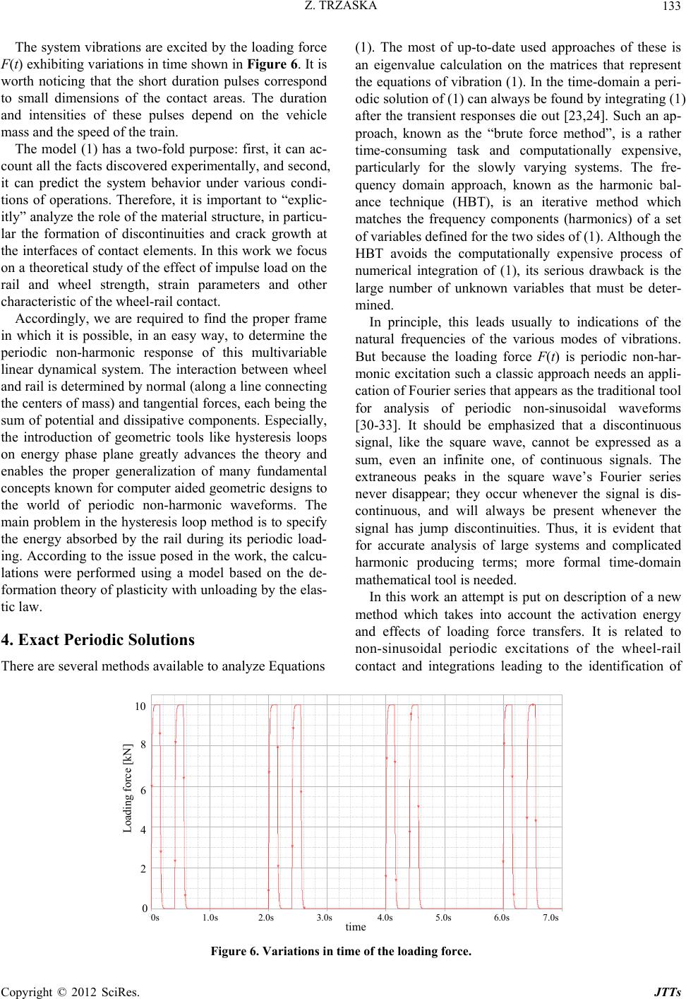 Z. TRZASKA Copyright © 2012 SciRes. JTTs 133 The system vibrations are excited by the loading force F(t) exhibiting variations in time shown in Figure 6. It is worth noticing that the short duration pulses correspond to small dimensions of the contact areas. The duration and intensities of these pulses depend on the vehicle mass and the speed of the train. (1). The most of up-to-date used approaches of these is an eigenvalue calculation on the matrices that represent the equations of vibration (1). In the time-domain a peri- odic solution of (1) can always be found by integrating (1) after the transient responses die out [23,24]. Such an ap- proach, known as the “brute force method”, is a rather time-consuming task and computationally expensive, particularly for the slowly varying systems. The fre- quency domain approach, known as the harmonic bal- ance technique (HBT), is an iterative method which matches the frequency components (harmonics) of a set of variables defined for the two sides of (1). Although the HBT avoids the computationally expensive process of numerical integration of (1), its serious drawback is the large number of unknown variables that must be deter- mined. The model (1) has a two-fold purpose: first, it can ac- count all the facts discovered experimentally, and second, it can predict the system behavior under various condi- tions of operations. Therefore, it is important to “explic- itly” analyze the role of the material structure, in particu- lar the formation of discontinuities and crack growth at the interfaces of contact elements. In this work we focus on a theoretical study of the effect of impulse load on the rail and wheel strength, strain parameters and other characteristic of the wheel-rail contact. Accordingly, we are required to find the proper frame in which it is possible, in an easy way, to determine the periodic non-harmonic response of this multivariable linear dynamical system. The interaction between wheel and rail is determined by normal (along a line connecting the centers of mass) and tangential forces, each being the sum of potential and dissipative components. Especially, the introduction of geometric tools like hysteresis loops on energy phase plane greatly advances the theory and enables the proper generalization of many fundamental concepts known for computer aided geometric designs to the world of periodic non-harmonic waveforms. The main problem in the hysteresis loop method is to specify the energy absorbed by the rail during its periodic load- ing. According to the issue posed in the work, the calcu- lations were performed using a model based on the de- formation theory of plasticity with unloading by the elas- tic law. In principle, this leads usually to indications of the natural frequencies of the various modes of vibrations. But because the loading force F(t) is periodic non-har- monic excitation such a classic approach needs an appli- cation of Fourier series that appears as the traditional tool for analysis of periodic non-sinusoidal waveforms [30-33]. It should be emphasized that a discontinuous signal, like the square wave, cannot be expressed as a sum, even an infinite one, of continuous signals. The extraneous peaks in the square wave’s Fourier series never disappear; they occur whenever the signal is dis- continuous, and will always be present whenever the signal has jump discontinuities. Thus, it is evident that for accurate analysis of large systems and complicated harmonic producing terms; more formal time-domain mathematical tool is needed. In this work an attempt is put on description of a new method which takes into account the activation energy and effects of loading force transfers. It is related to non-sinusoidal periodic excitations of the wheel-rail contact and integrations leading to the identification of 4. Exact Periodic Solutions There are several methods available to analyze Equations 0s1.0s 2.0s .0s .0s .0s .0s 7.0s Loadin force kN 10 8 6 4 2 0 0s 1.0s 2.0s 3.0s 4.0s 5.0s 6.0s 7.0s time Loading force [kN] Figure 6. Variations in time of the loading force.  Z. TRZASKA 134 response waveforms. Taking into account the above re- quirements and insufficiencies of the methods based on Fourier series, which are up-to-date most commonly used for studies of periodic non-harmonic states of linear sys- tems we propose in the sequel new method for obtaining, in closed form, the response of any linear system corre- sponding to piecewise-continuous periodic non-harmonic forcing terms. This newly involved approach is based on the exact solution of (1), segment concatenation and pe- riodizer functions. In our approach, the solution is exact, and by means of suitable unification of its piecewise representation, we can get with ease the exact expres- sions for its time derivatives. The method presented here depends on a “saw-tooth waveform” and a scheme used for unified representation of composite periodic non- harmonic waveforms. We discuss properties of linear systems with periodic non-harmonic excitations and de- velop a systematic Fourier series-less method for their studies. From this basis, more advanced theoretical re- sults are developed. The main feature of this method is the complete elimination of the frequency analysis what leads to significant simplifications in the process analysis. The second important feature is that that method is based on appropriate loops on the energy phase plane leading to an easy estimation of the energy delivery to the wheel-rail contact process through the evaluation of the loop’s area. Taking into account the periodic supplying force F(t) with pulses within each period we can represent it by more suitable form shown in Figure 7. T = T1 + T2 + T3 + T4 The supplying force F(t) = F(t + T) with two pulses within each period can be represented as follows 1 1 23 3 for 0 0 for for 0 for 2 tT TtT FtFt T TtT TtT (2) where A and Tk, with k = 1, 2, 3, denote the magnitude and moments, respectively, describing the pulses in the supplying force. The pulsed supplying force (2) can be represented by more convenient formula when introducing the unit Heaviside functions Hk(t, Tk), k = 1, 2, 3 which are shifted at the portions of period with respect to the origin point t = 0, namely 3 1 ,1 k k k tA HtTA 3 (3) A steady-state periodic solution of Equation (1) de- pends on system eigenfrequencies 121 1343 and sjssj (4) where 1j and the real and imaginary components of the system eigenfrequencies are determined by system parameters. It is easily seen from (1) and (3) that the re- sulting steady state coordinate z(t) can be expressed as follows 3 11 1 ,kk k k ztztTz tHtTztzt (5) where zk(t), k = 1, 2, 3, 4 denote the coordinate compo- nents in the successive parts, respectively, of the supply- ing force period. When t(Tk, Tk + 1) and the supplying force is equal to A or 0 with k = 1, 2, 3, 4 we obtain Loading force [kN] 10 8 6 4 2 0 0s 1.0.s 2.0s 3.0s 4.0s 5.0s 6.0s 7.0s Time T 1 T 2 T 3 Figure 7. Loading force with ideal pulses within the period. Copyright © 2012 SciRes. JTTs  Z. TRZASKA 135 4 , 1 m st kmk m ztBe Z , fk (6) where Zf,k denotes the steady state term forced by Fk and Bm,k , m = 1, 2, 3, 4, are constants to be determined from continuity and periodicity conditions fulfilled by respect- tive components of the system whole response. The steady state forced term Zf,k follows from Equa- tions (1) when successively substituting Fk, respectively. In result we get , rs k rs kk k F kk (7) To determine integration constants Bm,k we take into account the continuity and periodicity conditions which must be fulfilled by the coordinates z(t) and zs(t) [10]. For the sake of compactness of presentation we trans- form Equation (1) into standard state variable equation 1 tt xAxgt (8) where vectors x(t) and g(t) as well as constant element matrix A1 have appropriate dimensions. Here it is worth noticing that A1 must be non-critical with respect to T, i.e. the relation 1 det 0 T e A I (9) must be fulfilled. Since all eigenvalues of the studied system have nega- tive real parts, it is clear that A1 is non-critical and the condition (9) is satisfied. We now turn to describe an algorithm to compute a periodic solution for (8). The procedure for obtaining the steady state solutions of (8) is as follows. The periodizer function π arctan cot 2π TT pt t T (10) is established to have period T. In the presented proce- dure we construct the solution for one period [0, T) and then extend that solution to be periodic on the whole t line. This process is called the segment concatenation. Generalizing (3) to the case of forcing term in (8) we represent g(t) by a set of continuous terms gk(t) in the subintervals of [0, T). Such a division yields the respect- tive solutions xk(t) of x(t) that are determined as 1, t kk k te A xJX (11) for k = 1, 2, 3 ,4, where Xf,k is a forced steady state (index f) solution of (8) and has the same waveform shape as that of gk(t) in the corresponding subinterval, and Jk is a constant vector to be determined. We can find vectors Jk by analyzing the periodicity condition for the total solu- tion as follows 1 1,1 T fe A 4 xJ ,1 X (12) and from the continuity conditions it follows that 11 ,1 TT kk kfkk fk ee X AA JJ (13) for k = 1, 2, .3. Because the period [0, T) is divided into subintervals [tk, tk+1), k = 0, 1, 2, 3, then (12), (13) yield the block matrix equation 1 ,1 1 12 12,1 2 12 12,3 3 13 13,3 4 00 00 00 00 T f TT f TT f TT f e ee ee ee A AA AA AA IX J X J X J X J (14) From the Kronecker-Weierstrass form [35] it follows that the system (14) has a unique solution {J1, ··· , J4} for any T, t1, ··· , t3, and A1 Using the periodizer function p(t) we sew on continuous solutions in all subintervals during the concatenation process yielding periodic steady state solutions. Because the solutions are exact, the typi- cal drawbacks of classical methods, such as the Gibbs effect [5], are avoided 5. One-Period Energy Conception The approach presented in the previous sections can be applied to compute energy delivered by the independent supplying force to the load elements. Under periodic conditions the delivered energy is measured by one pe- riod energy loops on the energy phase plane. This new concept has been discussed in more details in the recent papers [32-34]. Then the total energy, WT delivered by supplying force F(t) = F(t + T) in one period equals 0(0) dd zT T T z WFtvtt Ftzt (15) where vt zt denotes the velocity of the rigid rail oscillations. The above integral is of the Riemann- Stieltjes type. The solutions obtained by using the perio- dizer and concatenation procedure can be easily used in (15) to find WT. We illustrate the concatenation proce- dure with two numerical examples. Example 1. Consider a particular case of the system shown in Figure 5 with forcing term F(t) characterized by A = 110 kN, T1 = 0.15 s, T2 = T3 = T = 2 s and M = 110 kg. The rigid sleeper is directly incorporated to the rigid foundation. We take into account the remaining parameters: br = 632 Ns/m and kr = 2.5 kN/m. Perform- ing computations in accord to the above presented algo- rithm yields the one-period energy loop that is presented in Figure 8. It can be easily found that the energy deliv- ered by the loading force F(t) equals WT = 110 kN·0.6 cm = 0.66 kJ. Copyright © 2012 SciRes. JTTs  Z. TRZASKA 136 For the comparison purposes we have considered the same as the above system but with F(t) =110 sin(20 πt) kN. The result of computation is presented in Figure 9. Note, that sinusoidal loading force of the same magni- tude excites vibrations exhibiting much smaller magni- tude and delivers smaller one-period energy than in the case of pulsed force. Figure 9 shows the one period en- ergy loop involved by sinusoidal loading force. The one-period energy was computed by using the Matlab function quad.m to yield WTsin = 0.124 kJ. Example 2. Let us consider the system shown in Fig- ure 5 with an elastic sleeper that is connected with the rigid foundation with a spring and a damper. The data given in Example 1 are supplemented with the sleeper mass Ms = 156 kg and remaining parameters: bs = 520 Ns/m and ks = 1.5 kN/m. For the above taken data we have determined the one-period energy loop that is shown in Figure 10. The computed one-period energy equals WT2 = 1.485 kJ. It has to be noted that for the loading force exhibiting two identical pulses within the period the magnitude of the rail vibrations is much greater and the one-period energy delivered to the system is more than five times greater with respect to the case of one pulse within the period. If the loading force F(t) takes sinusoidal form with the same magnitude and frequency f = 10 Hz then the one period energy delivered to the system has the form shown in Figure 11. The area of this loop equals - 10 0 20 40 60 80 100 120 F(t) [kN] Z t cm 1.0 0.5 0 -0.5 Figure 8. One-period energy loop for loading force with one pulse within the period and rigid sleeper. -150 -100 -50 050 100 150 -150 -100 -50 0 50 100 150 F t [kN] z(t)[mm] 1.5 1.0 0.5 0 -0.5 -1.0 -1.5 -150 Figure 9. One-period energy loop for sinusoidal loading force. Copyright © 2012 SciRes. JTTs 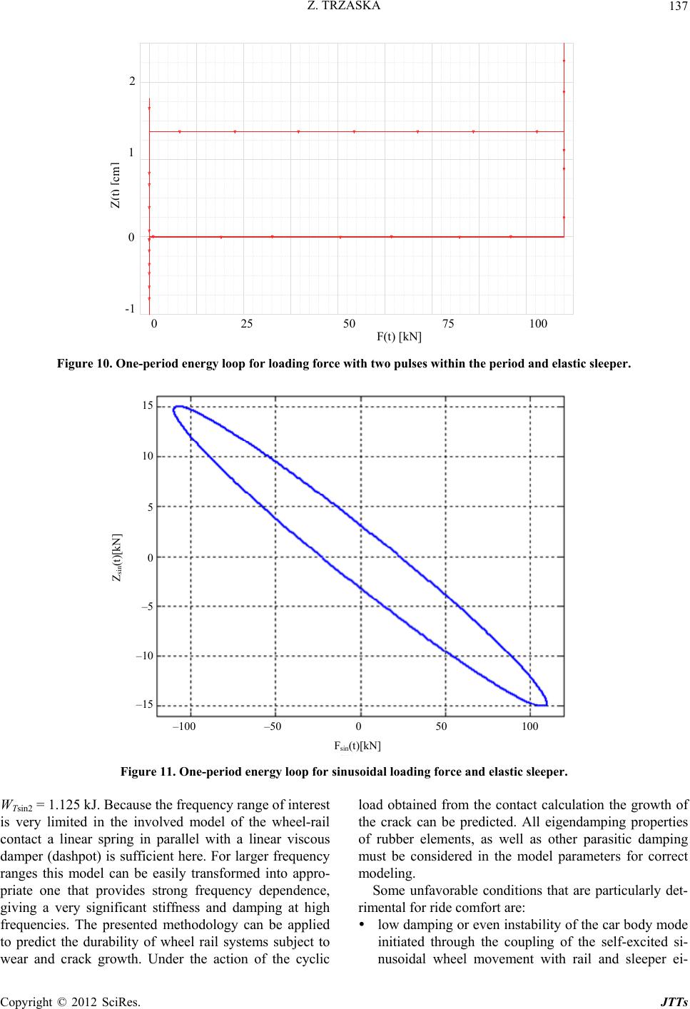 Z. TRZASKA 137 0 25 50 75 100 F(t) [kN] 2 1 0 -1 Figure 10. One-period energy loop for loading force with two pulses wi thin the period and elastic sleeper. 100 –50 0 50 100 F sin (t)[kN] 15 10 5 0 –5 –10 –15 Z sin (t)[kN] Figure 11. One-period energy loop for sinusoidal loading force and elastic sleeper. WTsin2 = 1.125 kJ. Because the frequency range of interest is very limited in the involved model of the wheel-rail contact a linear spring in parallel with a linear viscous damper (dashpot) is sufficient here. For larger frequency ranges this model can be easily transformed into appro- priate one that provides strong frequency dependence, giving a very significant stiffness and damping at high frequencies. The presented methodology can be applied to predict the durability of wheel rail systems subject to wear and crack growth. Under the action of the cyclic load obtained from the contact calculation the growth of the crack can be predicted. All eigendamping properties of rubber elements, as well as other parasitic damping must be considered in the model parameters for correct modeling. Some unfavorable conditions that are particularly det- rimental for ride comfort are: low damping or even instability of the car body mode initiated through the coupling of the self-excited si- nusoidal wheel movement with rail and sleeper ei- Copyright © 2012 SciRes. JTTs  Z. TRZASKA 138 genmodes; resonance from the eigenmode of the vehicle compo- nents with the periodic excited loading force. To study the influence of vehicle speed, we have to consider the excitation by track unevenness. This prob- lem is not considered in this paper for the sake of pres- entation compactness. In the next Section influences of nonlinear characteristics of the elastic support will be considered. 6. Sleeper Nonlinear Characteristics In order to check the efficiency of the proposed method which completely eliminates the Fourier series approach as well as to exhibit its advantages in applications the above established model of the wheel-rail contact dy- namics has been applied to that same roll plane but with taking into account a nonlinear characteristic of the sleeper with respect the ground. It is represented by the relation 2 22 3 ss zk zz (16) where constant parameters k2, α and β can be considered as bifurcating values. For α = 1.75, β = –1 the plot of the relative value f2/k2 is shown in Figure 12. In our approach, periodic solutions were determined by appropriate modifications of standard numerical solver used for solutions of nonlinear ordinary differential equations [36]. They appear as computationally not ex- pensive alternatives to the traditional harmonic balance approach and lead to quite satisfactory results. For a set of system parameters and the forcing term shown in Figure 7 and nonlinearity presented in Figure 12 the calculated time variations of the wheel-rail contact de- formations are depicted in Figure 13. Then using the alternative expression for the one-period energy, 00 dd PT T T P WFtvtt vtPt (17) where 0d t Pt F denotes the force impulse we can determine the energy absorbed by the rail during one-period of the applied force. The corresponding loop of one-period energy is presented in Figure 14. Applying suitable numerical procedure we can evaluate the loop surface which determines the energy absorbed by the rail during one-period of the force action. It takes value of 3.0 kJ. Observe that the nonlinearity influences the en- ergy absorbed by the rail at the contact of the wheel and rail in an important way. However, one can notice that the nonlinearity increases the absorbed energy in the contact. This is mainly due to the fact that, in these for- mulations, the motion of the wheel is assumed to travel with a constant forward velocity. Moreover, parameter -1 -0.500.5 11.5 2 0 0. 5 1 1. 5 zs(t)[cm] zs Nonlinear characteristic of the elastic sleeper z s (t)[cm] Nonlinear characteristic of the elastic sleeper f 2 (zs)/k 2 Figure 12. Nonlinear characteristic of the sleeper stiffness. Copyright © 2012 SciRes. JTTs 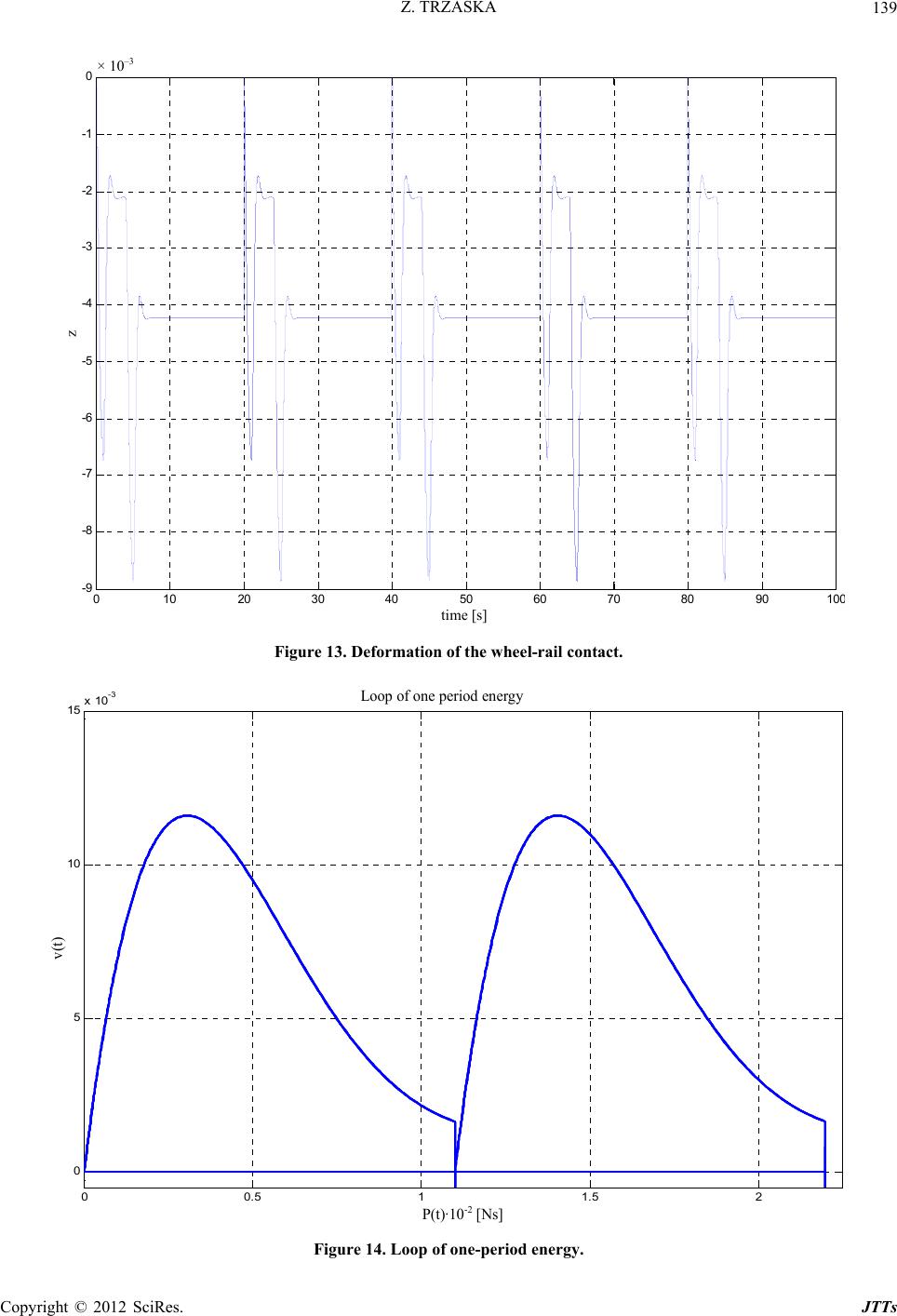 Z. TRZASKA 139 010 20 30 40 50 60 70 80 90 10 -9 -8 -7 -6 -5 -4 -3 -2 -1 0x 10 - time[s] z time [s] z × 10 –3 Figure 13. Deformation of the wheel-rail contact. 00.5 11.5 2 0 5 10 15 x 10 -3 P(t)*10 -2 [Ns] v(t) Loop of one-period energy P(t)·10 -2 [Ns] v(t) Loop of one period energy Figure 14. Loop of one-period energy. Copyright © 2012 SciRes. JTTs 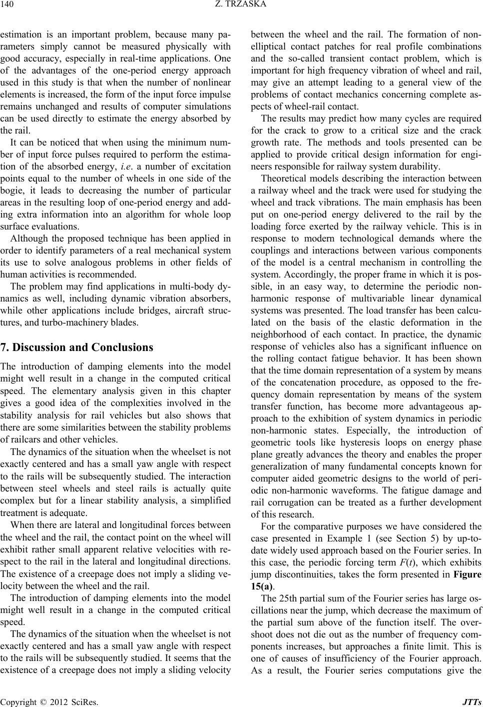 Z. TRZASKA Copyright © 2012 SciRes. JTTs 140 estimation is an important problem, because many pa- rameters simply cannot be measured physically with good accuracy, especially in real-time applications. One of the advantages of the one-period energy approach used in this study is that when the number of nonlinear elements is increased, the form of the input force impulse remains unchanged and results of computer simulations can be used directly to estimate the energy absorbed by the rail. It can be noticed that when using the minimum num- ber of input force pulses required to perform the estima- tion of the absorbed energy, i.e. a number of excitation points equal to the number of wheels in one side of the bogie, it leads to decreasing the number of particular areas in the resulting loop of one-period energy and add- ing extra information into an algorithm for whole loop surface evaluations. Although the proposed technique has been applied in order to identify parameters of a real mechanical system its use to solve analogous problems in other fields of human activities is recommended. The problem may find applications in multi-body dy- namics as well, including dynamic vibration absorbers, while other applications include bridges, aircraft struc- tures, and turbo-machinery blades. 7. Discussion and Conclusions The introduction of damping elements into the model might well result in a change in the computed critical speed. The elementary analysis given in this chapter gives a good idea of the complexities involved in the stability analysis for rail vehicles but also shows that there are some similarities between the stability problems of railcars and other vehicles. The dynamics of the situation when the wheelset is not exactly centered and has a small yaw angle with respect to the rails will be subsequently studied. The interaction between steel wheels and steel rails is actually quite complex but for a linear stability analysis, a simplified treatment is adequate. When there are lateral and longitudinal forces between the wheel and the rail, the contact point on the wheel will exhibit rather small apparent relative velocities with re- spect to the rail in the lateral and longitudinal directions. The existence of a creepage does not imply a sliding ve- locity between the wheel and the rail. The introduction of damping elements into the model might well result in a change in the computed critical speed. The dynamics of the situation when the wheelset is not exactly centered and has a small yaw angle with respect to the rails will be subsequently studied. It seems that the existence of a creepage does not imply a sliding velocity between the wheel and the rail. The formation of non- elliptical contact patches for real profile combinations and the so-called transient contact problem, which is important for high frequency vibration of wheel and rail, may give an attempt leading to a general view of the problems of contact mechanics concerning complete as- pects of wheel-rail contact. The results may predict how many cycles are required for the crack to grow to a critical size and the crack growth rate. The methods and tools presented can be applied to provide critical design information for engi- neers responsible for railway system durability. Theoretical models describing the interaction between a railway wheel and the track were used for studying the wheel and track vibrations. The main emphasis has been put on one-period energy delivered to the rail by the loading force exerted by the railway vehicle. This is in response to modern technological demands where the couplings and interactions between various components of the model is a central mechanism in controlling the system. Accordingly, the proper frame in which it is pos- sible, in an easy way, to determine the periodic non- harmonic response of multivariable linear dynamical systems was presented. The load transfer has been calcu- lated on the basis of the elastic deformation in the neighborhood of each contact. In practice, the dynamic response of vehicles also has a significant influence on the rolling contact fatigue behavior. It has been shown that the time domain representation of a system by means of the concatenation procedure, as opposed to the fre- quency domain representation by means of the system transfer function, has become more advantageous ap- proach to the exhibition of system dynamics in periodic non-harmonic states. Especially, the introduction of geometric tools like hysteresis loops on energy phase plane greatly advances the theory and enables the proper generalization of many fundamental concepts known for computer aided geometric designs to the world of peri- odic non-harmonic waveforms. The fatigue damage and rail corrugation can be treated as a further development of this research. For the comparative purposes we have considered the case presented in Example 1 (see Section 5) by up-to- date widely used approach based on the Fourier series. In this case, the periodic forcing term F(t), which exhibits jump discontinuities, takes the form presented in Figure 15(a). The 25th partial sum of the Fourier series has large os- cillations near the jump, which decrease the maximum of the partial sum above of the function itself. The over- shoot does not die out as the number of frequency com- ponents increases, but approaches a finite limit. This is one of causes of insufficiency of the Fourier approach. As a result, the Fourier series computations give the 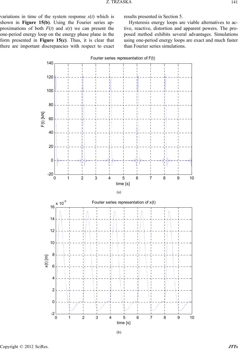 Z. TRZASKA 141 variations in time of the system response x(t) which is shown in Figure 15(b). Using the Fourier series ap- proximations of both F(t) and x(t) we can present the one-period energy loop on the energy phase plane in the form presented in Figure 15(c). Thus, it is clear that there are important discrepancies with respect to exact results presented in Section 5. Hysteresis energy loops are viable alternatives to ac- tive, reactive, distortion and apparent powers. The pro- posed method exhibits several advantages. Simulations using one-period energy loops are exact and much faster than Fourier series simulations. 0 12 3 45 6 7 8910 -20 0 20 40 60 80 100 120 140 time [s] F(t) [kN] Fouri er seri es repres entati on of F(t ) (a) 0 12 3 45 6 7 8910 -2 0 2 4 6 8 10 12 14 16 x 10 -3 time [ s] x(t) [m] Fourier series repres ent at i on of x (t ) (b) Copyright © 2012 SciRes. JTTs 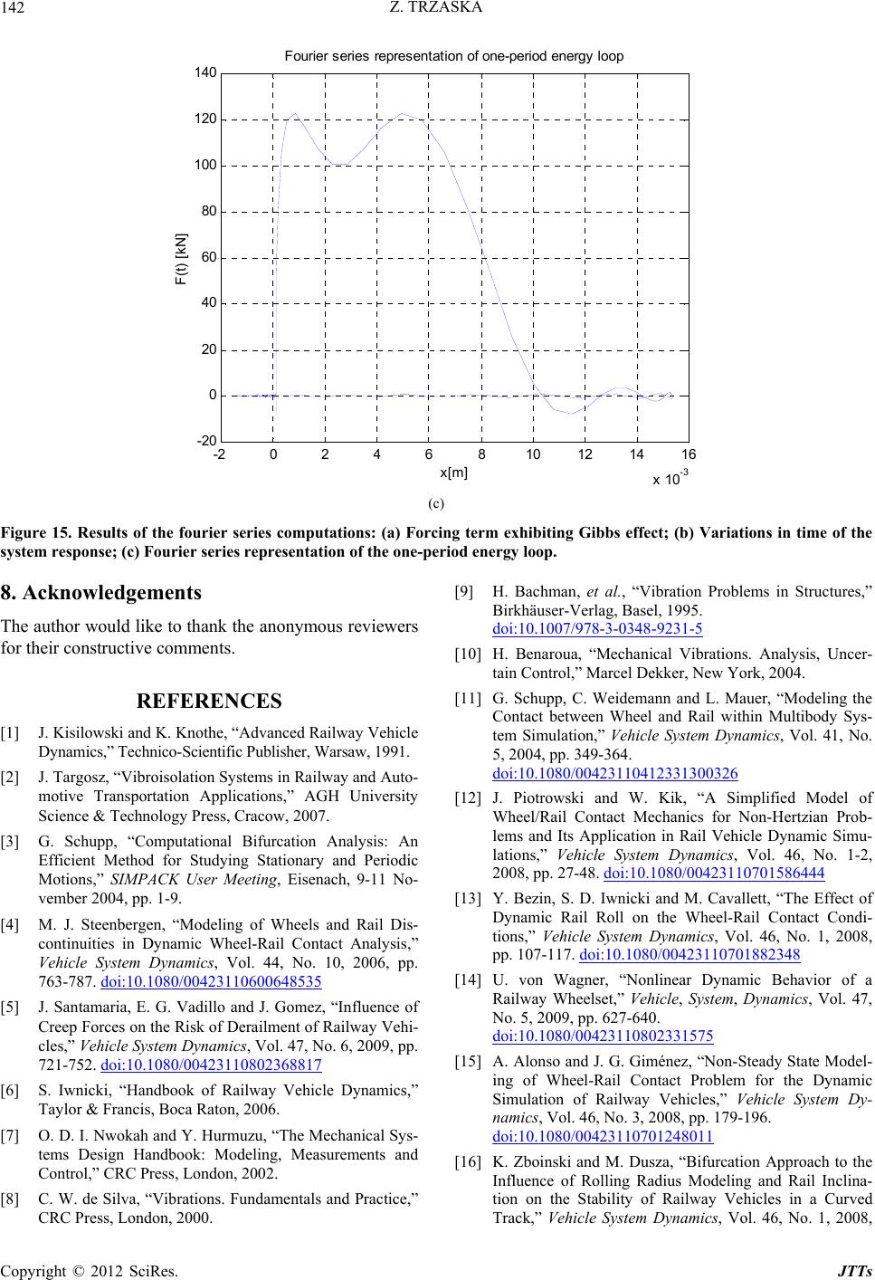 Z. TRZASKA 142 -2 0 2 4 6810 12 14 16 x 10 -3 -20 0 20 40 60 80 100 120 140 x[m] F(t) [kN] Fourier s eri es repres ent ati on of one-period energy l oop (c) Figure 15. Results of the fourier series computations: (a) Forcing term exhibiting Gibbs effect; (b) Variations in time of the system response; (c) Fourier series representation of the one-period energy loop. 8. Acknowledgements The author would like to thank the anonymous reviewers for their constructive comments. REFERENCES [1] J. Kisilowski and K. Knothe, “Advanced Railway Vehicle Dynamics,” Technico-Scientific Publisher, Warsaw, 1991. [2] J. Targosz, “Vibroisolation Systems in Railway and Auto- motive Transportation Applications,” AGH University Science & Technology Press, Cracow, 2007. [3] G. Schupp, “Computational Bifurcation Analysis: An Efficient Method for Studying Stationary and Periodic Motions,” SIMPACK User Meeting, Eisenach, 9-11 No- vember 2004, pp. 1-9. [4] M. J. Steenbergen, “Modeling of Wheels and Rail Dis- continuities in Dynamic Wheel-Rail Contact Analysis,” Vehicle System Dynamics, Vol. 44, No. 10, 2006, pp. 763-787. doi:10.1080/00423110600648535 [5] J. Santamaria, E. G. Vadillo and J. Gomez, “Influence of Creep Forces on the Risk of Derailment of Railway Vehi- cles,” Vehicle System Dynamics, Vol. 47, No. 6, 2009, pp. 721-752. doi:10.1080/00423110802368817 [6] S. Iwnicki, “Handbook of Railway Vehicle Dynamics,” Taylor & Francis, Boca Raton, 2006. [7] O. D. I. Nwokah and Y. Hurmuzu, “The Mechanical Sys- tems Design Handbook: Modeling, Measurements and Control,” CRC Press, London, 2002. [8] C. W. de Silva, “Vibrations. Fundamentals and Practice,” CRC Press, London, 2000. [9] H. Bachman, et al., “Vibration Problems in Structures,” Birkhäuser-Verlag, Basel, 1995. doi:10.1007/978-3-0348-9231-5 [10] H. Benaroua, “Mechanical Vibrations. Analysis, Uncer- tain Control,” Marcel Dekker, New York, 2004. [11] G. Schupp, C. Weidemann and L. Mauer, “Modeling the Contact between Wheel and Rail within Multibody Sys- tem Simulation,” Vehicle System Dynamics, Vol. 41, No. 5, 2004, pp. 349-364. doi:10.1080/00423110412331300326 [12] J. Piotrowski and W. Kik, “A Simplified Model of Wheel/Rail Contact Mechanics for Non-Hertzian Prob- lems and Its Application in Rail Vehicle Dynamic Simu- lations,” Vehicle System Dynamics, Vol. 46, No. 1-2, 2008, pp. 27-48. doi:10.1080/00423110701586444 [13] Y. Bezin, S. D. Iwnicki and M. Cavallett, “The Effect of Dynamic Rail Roll on the Wheel-Rail Contact Condi- tions,” Vehicle System Dynamics, Vol. 46, No. 1, 2008, pp. 107-117. doi:10.1080/00423110701882348 [14] U. von Wagner, “Nonlinear Dynamic Behavior of a Railway Wheelset,” Vehicle, System, Dynamics, Vol. 47, No. 5, 2009, pp. 627-640. doi:10.1080/00423110802331575 [15] A. Alonso and J. G. Giménez, “Non-Steady State Model- ing of Wheel-Rail Contact Problem for the Dynamic Simulation of Railway Vehicles,” Vehicle System Dy- namics, Vol. 46, No. 3, 2008, pp. 179-196. doi:10.1080/00423110701248011 [16] K. Zboinski and M. Dusza, “Bifurcation Approach to the Influence of Rolling Radius Modeling and Rail Inclina- tion on the Stability of Railway Vehicles in a Curved Track,” Vehicle System Dynamics, Vol. 46, No. 1, 2008, Copyright © 2012 SciRes. JTTs  Z. TRZASKA 143 pp. 1023-1037. doi:10.1080/00423110802037255 [17] K. Knothe and S. Stichel, “Schienenfahrzeugdynamik,” Springer, Berlin, 2007. [18] R. P. Feynman, “There’s Plenty of Room at the Bottom: An Invitation to Enter a New World of Physics,” Caltech Engineering and Science, Vol. 23, No. 5, 1960, pp. 22-36. http://www.zyvex.com/nanotech/feynman.html [19] C. W. de Silva, “Vibration and Shock Handbook,” Taylor & Francis, Boca Raton, 2005. [20] K. E. Drexler, “Nanosystems: Molecular Machinery, Manu- facturing, and Computation,” Wiley, New York, 1992. [21] V. L. Popov, et al., “Friction Coefficient in ‘Rail-Wheel’- Contacts as a Function of Material and Loading Parame- ters,” Physical Mesomechanics, Vol. 5, No. 3, 2002, pp. 113-120. [22] A. A. Shabanaa, K. E. Zaazaaa, J. L. Escalonab and J. R. Sany, “Development of Elastic Force Model for Wheel/ Rail Contact Problems,” Journal of Sound and Vibrations, Vol. 269, No. 1-2, 2004, pp. 295-325. doi:10.1016/S0022-460X(03)00074-9 [23] R. von Schwerin, “Multibody System Simulation: Nu- merical Methods, Algorithms, and Software,” Springer- Verlag, Berlin, 1999. [24] D. T. Greenwood, “Advanced Dynamics,” CUP, Cambridge, 2003. [25] J. Misiak and S. Stachura, “Selected Problems of Static Stability and Dynamics of Rod and Shell Structures,” Publishing Office of the Warsaw University of Ecology and Management, Warsaw, 2010. [26] W. Blajer, “A Geometrical Interpretation and Uniform Matrix Formulation of Multibody System Dynamics,” Zeitschrift für Angewandte Mathematik und Mechanik, Vol. 81, No. 4, 2001, pp. 247-259. [27] A. Orlova, Y. Boronenko, H. Scheffel, R Fröhling and W. Kik, “Tuning von Üterwagendrehgestellen Durch Rad- satzkopplungen,” ZEV-Glasers Annalen, Vol. 126, No. 4, 2002, pp. 270-282. [28] J. Evans and S. Iwnicki, “Vehicle Dynamics and the Wheel Rail Interface,” 2002. http://www.railtechnologyunit.com [29] D. Karnopp, “Vehicle Stability,” Marcel Dekker Inc., New York, 2004. doi:10.1201/9780203913567 [30] Z. Trzaska and W. Marszalek, “Periodic Solutions of DAEs with Applications to Dissipative Electric Circuits,” Proceedings of the IASTED Conference Modeling, Identi- fication and Control, Lanzarote, 6-8 February 2006, pp. 309-314. [31] Z. Trzaska, “Straightforward Method for Studies of Peri- odic Non-Harmonic States of Linear Systems,” Archive of Electrical Engineering, Vol. 53, No. 2, 2004, pp. 191- 215. [32] Z. Trzaska, “A New Approach to Shaping One-Period En- ergies of Dynamical Systems Operating in Non-Sinu- soidal States,” Archive of Electrical Engineering, Vol. 54, No. 3, 2005, pp. 265-287. [33] Z. Trzaska and W. Marszalek, “Computing Periodic So- lutions of Linear Differential-Algebraic Systems with Nonsinusoidal Excitations,” Archive of Electrical Engi- neering, Vol. 55, No. 3-4, 2006, pp. 255-271. [34] Z. Trzaska, “One-Period Energy in Dynamical Systems with Periodic Discontinuous Excitations,” Elektronika, Vol. 48, No. 3, 2007, pp. 26-32. [35] E. Zerzm, “Topics in Multidimensional Linear Systems Theory,” Springer, London, 2000. [36] R. R. Borrelli and C. S. Colleman, “Differential Equa- tions: A Modeling Perspective,” Wiley, New York, 2004. Copyright © 2012 SciRes. JTTs
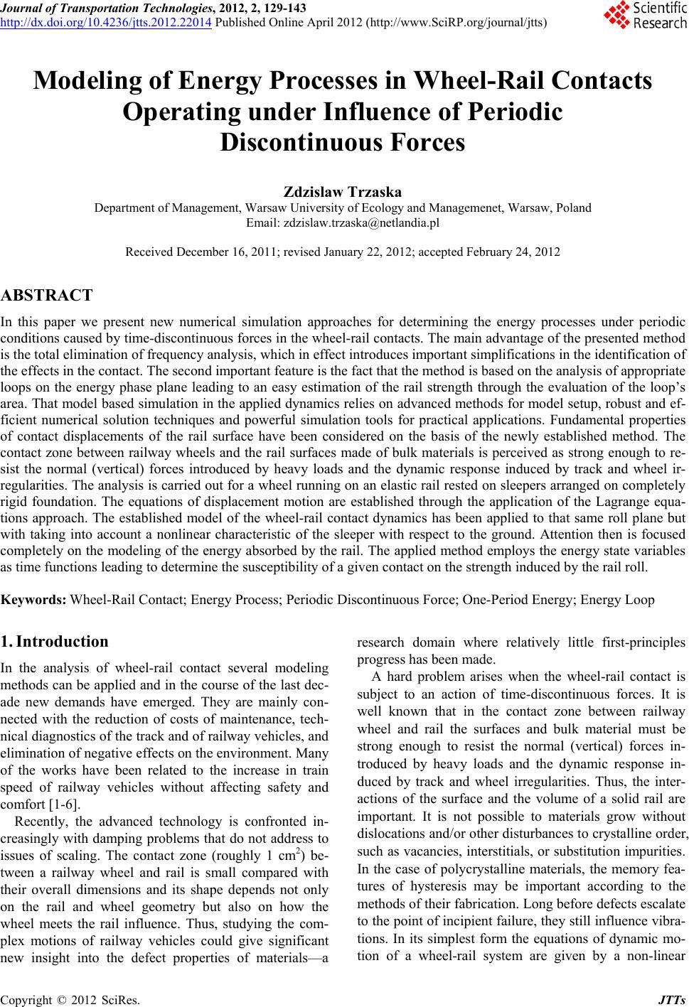
|