Paper Menu >>
Journal Menu >>
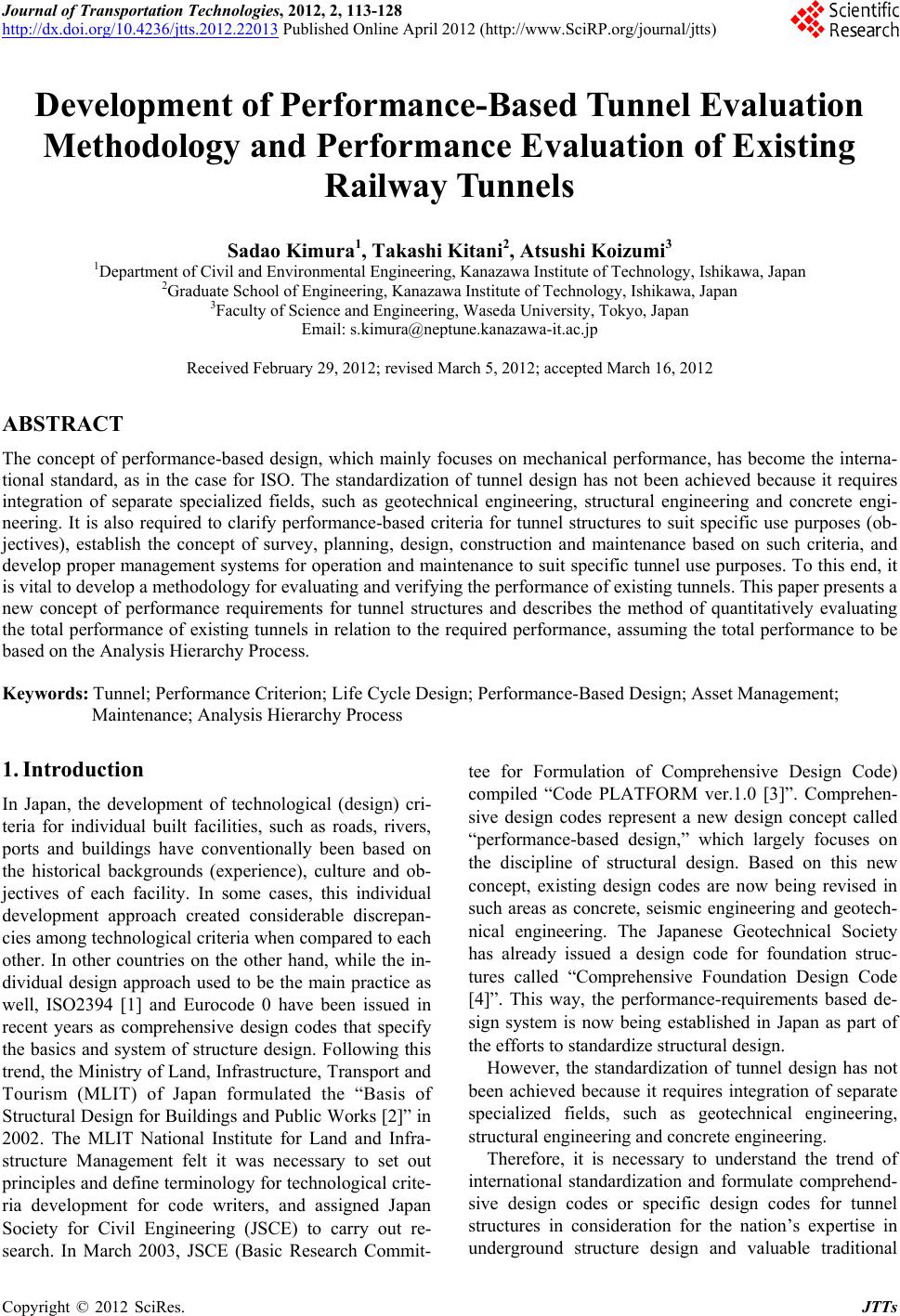 Journal of Transportation Technologies, 2012, 2, 113-128 http://dx.doi.org/10.4236/jtts.2012.22013 Published Online April 2012 (http://www.SciRP.org/journal/jtts) Development of Performance-Based Tunnel Evaluation Methodology and Performance Evaluation of Existing Railway Tunnels Sadao Kimura1, Takashi Kitani2, Atsushi Koizumi3 1Department of Civil and Environmental Engineering, Kanazawa Institute of Technology, Ishikawa, Japan 2Graduate School of Engineering, Kanazawa Institute of Technology, Ishikawa, Japan 3Faculty of Science and Engineering, Waseda University, Tokyo, Japan Email: s.kimura@neptune.kanazawa-it.ac.jp Received February 29, 2012; revised March 5, 2012; accepted March 16, 2012 ABSTRACT The concept of performance-based design, which mainly focuses on mechanical performance, has become the interna- tional standard, as in the case for ISO. The standardization of tunnel design has not been achieved because it requires integration of separate specialized fields, such as geotechnical engineering, structural engineering and concrete engi- neering. It is also required to clarify performance-based criteria for tunnel structures to suit specific use purposes (ob- jectives), establish the concept of survey, planning, design, construction and maintenance based on such criteria, and develop proper management syste ms for operation and maintenance to suit specific tunnel use pur poses. To this end, it is vital to develop a methodology for evaluating and verifying the performance of existing tunnels. This paper presents a new concept of performance requirements for tunnel structures and describes the method of quantitatively evaluating the total performance of existing tunnels in relation to the required performance, assuming the total performance to be based on the Analysis Hierarchy Process. Keywords: Tunnel; Performance Criterion; Life Cycle Design; Performance-Based Design; Asset Management; Maintenance; Analysis Hierarchy Process 1. Introduction In Japan, the development of technological (design) cri- teria for individual built facilities, such as roads, rivers, ports and buildings have conventionally been based on the historical backgrounds (experience), culture and ob- jectives of each facility. In some cases, this individual development approach created considerable discrepan- cies among technological criteria when compared to each other. In other countries on the other hand, while the in- dividual design approach used to be the main practice as well, ISO2394 [1] and Eurocode 0 have been issued in recent years as comprehensive design codes that specify the basics and system of structure design. Following this trend, the Ministry of Land, Infrastructure, Transport and Tourism (MLIT) of Japan formulated the “Basis of Structural Design for Buildings and Public Works [2]” in 2002. The MLIT National Institute for Land and Infra- structure Management felt it was necessary to set out principles and define terminology for technological crite- ria development for code writers, and assigned Japan Society for Civil Engineering (JSCE) to carry out re- search. In March 2003, JSCE (Basic Research Commit- tee for Formulation of Comprehensive Design Code) compiled “Code PLATFORM ver.1.0 [3]”. Comprehen- sive design codes represent a new design concept called “performance-based design,” which largely focuses on the discipline of structural design. Based on this new concept, existing design codes are now being revised in such areas as concrete, seismic engineering and geotech- nical engineering. The Japanese Geotechnical Society has already issued a design code for foundation struc- tures called “Comprehensive Foundation Design Code [4]”. This way, the performance-requirements based de- sign system is now being established in Japan as part of the efforts to standardize structural design. However, the standardization of tunnel design has not been achieved because it requires integration of separate specialized fields, such as geotechnical engineering, structural engineering and concrete engineering. Therefore, it is necessary to understand the trend of international standardization and formulate comprehend- sive design codes or specific design codes for tunnel structures in consideration for the nation’s expertise in underground structure design and valuable traditional C opyright © 2012 SciRes. JTTs  S. KIMURA ET AL. 114 technologies. On the other hand, it should be noted that the existing structures have been undergoing deterioration almost at the same time, notably since the turning of the century. Figure 1 shows a history of tunnel development in Japan denoted by tunnel length and construction year, featuring railway tunnels as an example. It has been pointed out that today’s infrastructure development should place im- portance on technolog ies that provide better maintenanc e of existing structures to prolong their service life, in ad- dition to new structure development technologies. In other words, there is a need to shift our behavior focus from new built environment development (monozukuri), i.e. building new structures as part of the infrastructure to “system development,” i.e. using existing structures in a sensible way in consideration for the specific mode of service assigned to each structure. This is also the case for the field of underground structures; structure design professionals are now required to shift design con cept for the better utilization of underground space in the future. The current focus on conventional design technologies, which aim to ensure structural safety based on the notion of new built environment development (monozukuri), should be shifted to the development of a new design approach called the “Life Cycle Design Method [6]”, which involves close examination of functions of struc- tures to better use the existing built environment and is employed throughout service life including the mainte- nance phase. Tunnels and other underground structures are different from ground structures in that they can not simply be abandoned once constructed; if an under- ground space becomes unused due to some defects and abandoned, certain disturbance in the surrounding ground may be caused in the long run, such as in the form of subsidence and deformation of foundations of adjacent structures. To serve as the international standard for the mainte- nance of existing structures, ISO13822 [7] was issued. Based on the concept of structure reliability and risk management, it sets forth the basic concepts of evaluat- ing existing structures (e.g. buildings and bridges) by Figure 1. Change in the railway tunnel length in Tokyo Metro [5]. classifying them into the following: 1) Expected modi- fication of use purpose, expected repairs, and prolonga- tion of design service life; 2) examination of reliability as required by the administrator and insurance company; 3) time-dependent deterioration caused by loading and ac- tions; and 4) damages, etc. caused by accidental actions. The code, however, does not describe how to evaluate the functions and service performance of a structure to ensure its original objectiv es. Considering the international trend of standardization of tunnel structures that focuses on performance criteria as described above, this paper first reestablishes the per- formance requirements for tunnel structures proposed by JSCE, and discusses the concepts of performance re- qui rements for existing tunnels in their maintenance phase and management strategies based on them [8,9]. The pa- per goes on to taking existing road tunnels as the exam- ple to describe the method of calculating the Total Per- formance Index designed to comprehensively evaluate their actual performance at the maintenance phase. 2. Performance Requirements [10] for Tunnel Structures Based on Specific Objectives 2.1. Concept of Performance Requirements The performance requirements for tunnels, which are used for various purposes such as roads, railways, water supply and sewage systems, power supply, and commu- nication, are designated individually to suit their specific objectives within the basic performance requirements. It should be noted that the concept of structural design of tunnel structures is significantly varied among construc- tion methods [11], and thus the specific performance requirements for a tunnel structure should be developed with careful consideration of its construction method. In the mountain tunnel construction method employed for considerably strong and highly self-supporting ground, the main structural system that provides a space to con- struct a tunnel is the natural ground itself, and thus the purpose of structural design is to maximize its natural capacity and provide manmade support. On the other hand, the shielding method, typically urban tunneling construction, is employed where hardly any self-support capacity is expected. The main structural system here should be manmade. This is one of the factors that make the structural design of tunnels difficult. It is thus neces- sary to identify major factors that differ between tunnel- ing methods. Table 1 shows an example of factors that differ between the mountain and shield tunneling meth- ods (for railway tunnels). When closely examining the required performance, these differences among tunneling methods should be taken into account. Copyright © 2012 SciRes. JTTs  S. KIMURA ET AL. Copyright © 2012 SciRes. JTTs 115 2.2. Development of Performance Requirement Specific performance requirements are developed here based on the basic ones. Table 2 shows an example of identification of performance requirements for road tun- nels constructed in the mountain tunneling method. The primary categories for required performance consist of the basic performance requirements and their descrip- tions. Secondary categories and subcategories consist of phenomena used for evaluating the primary categories and for further evaluating the secondary categories, re- spectively. This means the performance given by the primary categories is satisfied if all the subcategory phe- nomena are satisfied. It should be noted here that the subcategory phenomena consist of those that can directly be evaluated and those that cannot, and that some of them allow quantitative evaluation while others only al- low qualitative evaluation due to obscurity. To carry out the detailed evaluation of individual performance, spe- cific verification indexes should be developed for all phases of planning, design, construction, and mainte- nance (service) to evaluate the actual performance. Fo- cusing on the maintenance phase, the sections below de- scribe the concept of evaluation of actual performance and management concept based on performance criteria. Table 1. Differences in factors betwee n tunneling methods (for railw ay tunne ls). Mountain tunneling Shield tunneling Construction site Mainly mountain ous regions and su burbs (frost inside the tunnel considered) Mainly urban areas (frost inside the tunnel Not considered) Portal Entrance exists in principle No entrance in principle Construction load Not necessary to consider construction load in general May be disturbed by construction load Require measures for stabilizing the cutting face during construction Lining system The lining concrete does not serve as a structural member in general (Plain concrete system in principle) The lining (segment) serves as a structural member (Reinforced concrete, steel structure, and composite sys- tem) Roadbed Roadbed may be disturbed where there is no invert, affecting the running stability The closure system consisting of segments creates no disturbance Table 2. Performance requir eme nts fr agme nted (shield tunneling method/railw ay). Primary categories Secondary categories Subcategories Ensure safe driving Not directly threatening to user safety User safety Ensure user safety Ensure safe eva cuation of users in emergency Ensure ride quality User usability Ensure user comfort Not making users uncomfortable or feel insecure Ensure stability against continuous load Provide necessary seismic performance Ensure stability against assumed load change Structural stability Ensure stability against assumed load Ensure stability against assumed construction load High corrosion resistance No deterioration in concrete Durability Ensure durability against assumed deterioration factors Provide high water tightness Satisfy req uired demands (traffic capacity) Ensure trai ns can be operated in a stable manner (at the fixed time) Administrator usability Ensure proper utilization by administrator Ensure operation of auxiliary facilities for regular train operation Ensure safe & easy inspection Maintainability Ensure provision of proper maintenance Ensure safe & easy repair Minor impacts on ground water Minor impa cts on surrounding grounds To ensure required traffic volume safety and smoothly during the required service period Impact on surroundings Minimize impact on surroundings Minor impacts on surround ing real estates  S. KIMURA ET AL. 116 3. Performance Criteria Based Performance Criteria [12] 3.1. Concept of Management Based on Performance Criteria “Performance criteria based management” means a stra- tegic management in consideration of the lifecycle of the tunnel through deter mination of evaluation ind exes based on performance requirements at all phases of planning, survey, design, construction, and maintenance and through execution of performance verification based on such evaluation indexes. Figure 2 shows the management procedure based on pe rf o rmance criteria. The basic concept of performance-criteria based man- agement is to evaluate and verify the actual performance based on the same performance requirements for each phase of planning and design, construction, and mainte- nance (service) according to the use purpose (objectives) of a tunnel. To describe this concept, the maintenance phase of existing tunnel structures is highlighted here. Conventionally, in the maintenance of existing tunnel structures, inspection, evaluation and remedial measures have been carried out or devised by setting individual criteria [13]. Such maintenance basically focuses on the development of remedies for individual troubles, and does not take the procedure of identifying the perform- ance criteria, evaluating/verifying the actual performance, and devising necessary remedies. In practice, future measures are only considered on an as-needed basis within the limited budgetary restrictions. On the other hand, performance-criteria based man- agement is largely different in that it estimates future conditions based on the evaluation/verification of actual current performance, and makes decisions on the timing and method of remedies by employing the life cycle cost optimization approach based on the strategies of admin- istrator. It should be noted, however, that the evalua- tion/verification items used in the evaluation/verification of actual performance are not very different from con- ventional inspection items; each inspection item serves as a performance verification index or alternative perform- ance verification index used for evaluating or verifying the required performance. Figure 3 shows only the basic principles of evaluating /verifying the actual performance, as compared to the basic performance requirements. The figure shows some examples of performance verification indexes that allow quantitative evaluation, corresponding to the basic per- formance requirements. Some performance verification indexes are designed to evaluate by employing an analy- sis or statistical approach based on the yield strength of members, cracking and other data obtained in tunnel in- spection. As mentioned before, some indexes allow quan- titative evaluation and some do not. It is thus practical to base comprehensive performance verification on a rating method using verification criteria consisting of five or so grades. In so doing, it becomes possible to weigh the priority of each performance requirement in terms of such conditions o f target tunnel structure as use purpose, tunneling method, owner strategies and serviceability. For performance verification indexes that are difficult to evaluate quantitatively, the Analytic Hierarchy Process and other appropriate approaches, which will be men- tioned in later sections, are employed to manage quanti- tative evaluation. The Total Performance Index is ob- tained by performing evaluation /verification of actual Figure 2. Procedure for performance-based management. Copyright © 2012 SciRes. JTTs  S. KIMURA ET AL. 117 Figure 3. Concept of evaluation/verification method for current performance corresponding to the required performance. performance in the manner described above for each tunnel or span. This way, integrated management of the actual performance of tunnel structures becomes possi- ble. 3.2. Prediction of Future Conditions In performance-based management, it is required to en- sure tunnel performance with minimum costs during the target service period or the actual service period that ex- tends beyond the former. This concept is presented in Figure 4. To ensure the required performance in accor- dance with a reduction in the actual performance level, it is necessary to take measures for preven tive maintenance or preventive management [14]. However, evaluation of the actual performance often involves considerable un- certainties because, as mentioned before, tunnel struc- tures are constructed in highly uncertain ground. That means even where the average actual perform- ance meets performance requirements, the required per- formance may not be achieved when the damage prob- ability shown in Figure 5 is taken into account. In such cases, emergency remedies are required. Thus, the prop er procedure for tunnel structures should be to frequently perform inspection to check the actual performance and ensure preventive management that provides repairs be- fore the important actual performance, even if it is at the local level, becomes short of the required level [15]. It should also be noted that the inspection frequency con- Copyright © 2012 SciRes. JTTs  S. KIMURA ET AL. 118 Figure 4. Concept of maintenance optimization strategy. Figure 5. Concept of damage probability. siderably affects the accuracy of prediction of future conditions based on the current conditions. Figure 6 shows the concept of prediction accuracy in relation to inspection frequency. In the case of road tunnels for ex- ample, inspections are carried out almost every five years (every two years in more frequent cases) in general. An extremely low inspection frequency increases uncertain- ties. A reduction in the prediction accuracy is directly reflected in preventive management policies; it is thus necessary to properly determine the inspection frequency according to the serviceability of the tunnel. 3.3. Tunnel Serviceability The serviceability of a tunnel structure depends on such factors as the use purpose, social functions, administra- tor’s operation size, and financial resources, and is hence affected by the social roles and importance of the tunnel. It is thus necessary to determine the serviceability of each tunnel and consider a suitable management method. Table 3 shows the service levels derived from service- ability and correspond ing basic methods of management. The service levels are from “low” to “high”. Tunnels categorized as “high” are defined as those such as ex- pressways in urban areas having particularly significant social roles, which require detailed inspections and con- tinuous monitoring at the maintenance phase and evalua- tion/verification of actual performance using indexes that allow numerical expression to a maximum extent. Tun- nels categorized as “low”, on the other hand, are neces- sary for the society but are not very busy or subject to particularly tight budgetary restrictions by the adminis- trator. Such differences in serviceability should also be taken into consideration in the management method. 4. Evaluation/Verification of Actual Performance of Tunnels by Rating 4.1. Concept of Evaluation/Verification of Actual Performance of Tunnels by Rating [15] The procedure for evaluating/verifying the actual per- formance by rating consists of identification of evalua- tion/verification indexes or alternative indexes for each item of performance requirements; determination of standard performance values in five grades for each in- dex; calculation of actual performance values; integrate the values to obtain the Total Performance Index; and perform evaluation/verification using the Total Perform- ance Index. Tables 4(a) and 4(b) show an example of relationship between performance requirement items and performance verification/alternative indexes derived from past design documents and inspections (shield tunnel- ing/railway tunnels). This approach allows integrated quantitative evalua- tion of changes with time in the actual performance of individual tunnels and is effective in formulating mid- to long-term strategies. Tunnel structures required to pro- vide a high level of serviceability need in-depth study of the probability of local damage and performance dete- ri o r ation, and more detailed evaluation/verification through an increased frequency of inspection, continuous moni- toring of locations having trouble risk, and calculations and statistical analysis using the insp ection data obtained. 4.2. Evaluation of Actual Performance by the Analytic Hierarchy Process [16] This section explains evaluation of the actual perform- Figure 6. Inspection frequency and accuracy of predicting future conditions. Copyright © 2012 SciRes. JTTs  S. KIMURA ET AL. Copyright © 2012 SciRes. JTTs 119 Table 3. Concept of serviceability-based management. Service level Low Low traffic volume/ Deterioration not progressed/Mountainous region High High traffic volume/ Deterioration highly progressed/ Important route/ Emergency transportatio n route Performance criteria User safety/Usability/Structural stability/Durability/Administrator usability/ Maintainability/ Impacts on the surroundings Performance verification i ndex Select indexes that allow numerical expression to a maximum extent Design method Presumptive design Performance design Monitoring Inspection + Simple measurements as needed Inspection + Measurements Soundness evaluation method Rating in principle Performance-based evaluation method Performanc e verification method at maintenance phase Rating based on results of inspection (+ sim p le measurements) Verification using numerical indexes, mainly derive d from measur ements Prediction method for future conditions Deterministic prediction (residual strength) Prediction with uncertainties considered, e.g. through probabilistic approach Decision making through LCC optimization Life cycle costs assuming inspections and repairs Perform optimization of life cycle costs 4.3. AHP-Based Evaluation of Actual Performance and Current Inspection Evaluation [16] ance of a tunnel by the Analytic Hierarchy Process (“AHP”) using lining data obtained from daily and regu- lar inspections (observation/measurement data inside the tunnel). The Total Performance Index, TPI per tunnel span is given by The actual performance is evaluated in AHP using the inspection results for railway tunnels constructed in the shield tunneling method. Two types of single track shield tunnels, i.e. a small-to-medium box segment section. 1 N ii i TPIP C (1) Rating tunnels using performance evaluation criteria based on the interior view of lining drawn from the re- sults of inspection on 350 rings of box segment section, TPI is calculated using Equation (1). The results are compared against those of existing inspection evaluation implemented [17] (hereinafter, the “existing method”), the validity of AHP-based quantitative performance evaluation method is examined. According to the exist- ing method, the soundness of tunnels is assessed in rela- tion to: a) Users (safety and usability); b) Structural sys- tems (load-bearing capacity and durability); c) Adminis- trator (maintenance); and d) Progressiveness and (com- mon) characteristics of disturbance. Judgment criteria are defined for each of the following cases: 1) Disturbance is caused by external force (cracking); 2) By material dete- rioration; and 3) By water leakage. The soundness of tunnels is evaluated by th e judgment categories shown in Table 7, and then the timing of remedies is determined. The probability distributions of a set of TPI for each judgment result by the existing method are shown in Figure 7. where score given by the performance evaluation criteria, weighing factor derived from evaluation by advanced engineers, and the number of required performance evaluation item. Table 5 shows an example of weighing by evaluation by advanced engineers engaging in the design, construc- tion and management of tunnels, citing railway tunnels constructed in the shield tunneling method. By going through the procedure described above, each evaluation value (TPI) for each construction span is rep-resented numerically for all performance require- ments in an integrated way. The probability distributions that represent the route and a set of TPI per section give total generalized evaluation of actual performance of the target route and section. The performance evaluation criteria are defined in five grades for each required per- formance subcategory, i.e. 1) Undergoing no perform- ance deterioration or assumed to be so; 2) Undergoing slight performance deterioration; 3) Undergoing per- formance deterioration; 4) Undergoing remarkable per- formance deterioration; and 5) In need of immediate remedy), wh ich are scor ed 1, 3, 5, 7, and 15, respectively. Tables 6(a) and 6(b) show examples of performance evaluation criteria for railway tunnels constructed in the shield tunneling method. In the case of box segment, the average values of TPI are 1.006, 1.074, 1.335, and 2.446 for Judgment Cate- gory S, C, B and A, respectively. It is thus indicated that TPI more or less represen ts the otal results obtained in the existing method. These re- t  S. KIMURA ET AL. 120 Table 4(a). Performance requireme nts fr agmented (shie l d tunneling method/railway). Performance requirements Primary categories Secondary categoriesSubcategories Performance evaluation items Ensure good railway track alignment1Amount of tra c k d i s p l a c e ment (any impacts on driving safety) 2Amount of displ a cement in tunnel alignment 3 Conditions of any cracking or loosening of segments/secondary lining and of any corrosion, etc. in rebars in a region(s) that may threaten driving safety (e.g. directly above the tracks) Ensure safe driving 4Exposure of tracks to leaked water Ensure safe driving Ensure proper construction gauge 5Leeway outside the construction gauge No flaking occurr ed 6 Conditions of any cracking or loosening of segments/secondary lining and of any corrosion, etc. in reinforcement\cement in a region(s) that may threaten driving safety (e.g. directly above the tracks) Not directly threatening to user safety No water leakage occurred 7Conditions of any water leakage in a region(s) that may threaten driving safety (e.g. platforms/concourse ceiling) User safety Ensure user safety Ensure safe evacuation of users in emergency Allow proper layout/usage of disaster prevention equipment and provide evacuation routes for users 8Leeway outside the construction gauge (clearance from disaster prevention equipment and room for evacuation) Ensure ride quality Ensure good alignment and avoid any tunnel deformation that affects riding comfort 9Amount o f track displacement (any impacts on riding comfort) User usability Ensure user comfort Not making users uncomfortabl e or feel insecure No water leakage/cracking that makes users uncomfortable o r feel insecure is observed 10 Development of water leakage/ cracking in a region(s) visible to users (e.g. platforms/concourse ceiling) 11 Amount of tunne l convergence 12 Development of cracking or damag e in segments or secondary lining (structural deformation) Ensure stability against continuous load Provide necessary load-bearing performance against continuous load 13 Stress intensity or stress resultant of lining obtained in deformation analysis Provide necessary seismic performance Lining provides necessary seismic performance against earthquake motions assumed during service life 14 Identification of s eismic performance and damage level by analysis 15 Amount of tunnel convergence and linear displacement Ensure stability against assumed load change Provide required load bearing capacity against impacts by neighboring co nstruction work and load condition changes caused by change in surrounding environment assumed during service life 16 Stress intensity or stress resultant of lining obtained in impact analysis Ensure stability against assumed load Ensure stability against assumed load High corrosion resistance Lining provides necessary seismic performance against earthquake motions assumed during service life 17 Not evaluated in the maintenance phase 18 Presence of cracking/loosening, etc. in segments and secondary lining 19 State of corrosion in rebars, bolts and splice plates High corrosion resistance Rebars & steel segments with minimum speed of rust development in steels, e.g. bolts and splice plate 20 Degradation indexes, e.g. cover concrete, remaining non-carbonated depth, chloride concentration, and water content No deterioration in concrete No erosion or de terioration in liming concrete 21 State that cracking/erosion of segments and secondary lining Durability Ensure durability against assumed deterioration factors Provide high water tightness Minimize inducing any wa t er leak that may cause deterioration of lining/equipment 22 Occurrence of water leakage Copyright © 2012 SciRes. JTTs  S. KIMURA ET AL. 121 Table 4(b). Performance requirements fragmented (shield tunneling method/railway). Performance requirements Primary categories Secon dary categories Subcategories Performance evaluation items Satisfy requi red demands (traffic capacity) Provide an inner space that accommodates the required number of railway tracks. En-sure the alignment is designed to allow the required train speed. 23Not evaluated in the maintenance phase 24 State of e.g. cracking and loosening in the regions of segments/secondary lining that affect auxiliary facilities involved in train operation. 25 State of corrosion in steels in a region(s) that may affect auxiliary facilities involved in train operation Ensure trains can be operated in a stable manner (at the fixed time) Prevent the occurrence of water leakage or flaking that may obstruc t the functions of auxiliary facilities involved in train operation 26 State of water leakage in regions that affect auxiliary facilities involved in train operation Allow proper lay-out/usage of auxiliary facilities involved in train operation 27 Allowances outside the construction gauge, esp. in relation to auxiliary facilities Administrator usability Ensure proper utilization by administrator Ensure operati o n of auxiliary facilities for regular train operation Water inside the tunnel is properly drained to avoid any impacts on auxiliary facilities 28 Conditions of drainage facilities (e.g. blockage of drain ditches) Ensure safe & easy inspection Allow safe & easy daily patrolling, inspection and cleaning 29 Allowances outside the construction gauge (escape space used during patrolling/inspection) Maintainability Ensure provision of proper maintenance Ensure safe & easy repair Allow installation of scaffoldings and stockyards for repair/reinforcement works Proper margin for repair /reinforcement provided in the inner section 30 Not evaluated in the maintenance phase 31 Changes in the groundwater level in surrounding areas 32 Groundwater quality in nearby areas Minor impa cts on ground water Minimize g round-water leve l changes Do not affect groundwater contamination o n th e surroundings 33Water leakage survey inside the tunnel 34 Amount of ground surface displacement in surrounding areas Minor impa cts on surrounding grounds Minimize ground surface settlement/upheaval 35Occurrence of water leakage Minor impa cts on surrounding real estates Impacts on adjacent buildings/buried utilities are within the allowable range 36Amount of displacement or development of cracks in neighboring properties Impact on surroundings Minimize impact on surroundings Minor vibration and noise in the surroundings Minimize impact of vibration /noise on the surrounding due to operation of train 37 Vibration/noise levels of ground surface and surrounding buildings Copyright © 2012 SciRes. JTTs  S. KIMURA ET AL. 122 Table 5. Weighting factors given by evaluation by tunnel engineers. Primary categories weight factor (SD*) Secondary categories weight factor (SD*) Sub categories weight factor (SD*) No Avoid any tunnel deformation that may obstruct the ensure safe driving 0.052 (0.128) 1 Ensure good alignment and avoid any tunnel deformation that may obstruct the ensure safe driving 0.050 (0.148) 2,5 Ensure safe driving for users 0.152 (0.222) Prevent the occurrence of water leakage or flaking that may obstruct the ensure safe driving 0.050 (0.210) 3,4 Not directly threatening to user safety 0.092 (0.197) -(nothing) - 6,7 User safety 0.317 (0.125) Allow disaster prevention equipment to function in emergency 0.073 (0.191) -(nothing) - 8 Ensure ride quality 0.079 (0.235) -(nothing) - 9 User usability 0.124 (0.075) Not making users uncomfortable or feel insecure 0.045 (0.235) - (nothing) - 10 Ensure stability against continuous load 0.088 (0.146) -(nothing) - 11,12,13 Provide necessary seismic performance 0.039 (0.099) -(nothing) - 14 Ensure stability against assumed load change 0.047 (0.088) -(nothing) - 15,16 Structural stability 0.211 (0.093) Ensure stability against assumed construction load 0.037 (0.134) -(nothing) - 17 High corrosion resistance of steel 0.041 (0.162) -(nothing) - 18,19,20 No deterioration in concrete 0.037 (0.160) -(nothing) - 21 Durability 0.128 (0.085) Provide high water tightness 0.049 (0.209) -(nothing) - 22 Satisfy requir ed demands 0.011 (0.188) -(nothing) - 23 Ensure trains can be operated in a stable manner (at the fixed time) 0.015 (0.199) -(nothing) - 24,25,26 Allow proper layout/usage of auxiliary facilities involved in train operation 0.005 (0.235) 27 Administrator usability 0.037 (0.017) Ensure operati o n of auxiliary facilities for regular train operation 0.010 (0.162) Water inside the tunnel is properly drained to avoid any impacts on auxiliary facilities 0.005 (0.235) 28 Ensure safe & easy inspection 0.031 (0.213) -(nothing) - 29 Maintainability 0.056 (0.037) Ensure safe & easy repair 0.025 (0.213) -(nothing) - 30 Minor impacts on ground water 0.027 (0.152) -(nothing) - 31,32,33 Minor impacts on ground surface 0.027 (0.120) -(nothing) - 34,35 Minor impacts on surrounding real estates 0.036 (0.162) -(nothing) - 36 Impact on surroundings 0.127 (0.077) Minor vibration and noise in the surroundin gs 0.037 (0.178) -(nothing) - 37 Total (1.000) (1.000) (1.000) Copyright © 2012 SciRes. JTTs  S. KIMURA ET AL. 123 Table 6(a). Performance evaluation criteria used in AHP (shield tunne ling method/ railway tunnels). No Performance evaluation items Monitoring items The monitoring method is parenthesized 1 Amount of track displacement (any impacts on driving safety) Amount of track displacement 2 Amount of displac ement in tunnel alignment Differential leveling and tunnel center line survey 3 Conditions of any cracking or loosening of segments/secondary lining and of any corrosion, etc. in rebars in a region(s) that may threaten driving safety (e.g. directly above the tracks) • Location, length, width and range of cracking and corrosion: Visual observation and visible images • Loosening range : Hammering and infrared camera • Crack Pattern: Unfolded view of deformation • Progressiveness: Marking photographing, and cracking gauge • State of steel corrosion: Self potential, polarization resistance, and visual observation by chipping 4 Exposure of tracks to leaked water • Location and amount of water leakage: Visual observation • Quality of leaked water: Water quality test 5 Leeway outside the construction gauge • Measurement with a clearance car and electro-optical distance meter 6 Conditions of any cracking or loosening of segments/secondary lining and of any corrosion, etc. in reinforcement \cement in a region(s) that may threaten driving safety (e.g. direct ly above the tracks) • Location, length, width and range of cracking/damage: Visual observation and visible images • Loosening range : Hammering and infrared camera • Crack Pattern: Unfolded view of deformation • Progressiveness: Marking, p hotographing, and cracking gaug e • State of steel corrosion: Self potential, polarization resistance, and visual observation by chipping 7 Conditions of any water leakage in a region(s) that may threaten driving safety (e.g. platform s/concourse ceiling) • Location and amount of water leakage and visual ob servation 8 Leeway outside the construction gauge (clearance from disaster prevention equipment and room for evacuation) • Measurement with a clearance car and visual inspection 9 Amount of track displacement (any impacts on riding comfort) • Measurement of amount of track displacement and train oscillation 10 Development of water leakage/ cracking in a region(s) visible to users (e.g. platforms/concourse ceiling) • Visual observation 11 Am ount of tunnel conv ergence • Amount of convergence: Convergence gauge and electro-optical distance meter 12 Development of cracking or damage in segments or secondary lining (structural deformation) • Location, length, width and range of cracking/damage: Visual observation and visible images • Loosening range : Hammering and infrared camera • Crack Pattern: Unfolded view of deformation • Progressiveness: Marking ,photographing, and cracking gauge • State of steel corrosion: Self potential, polarization resistance, and visual observation by chipping 13 Stress intensity or stress resultant of lining obtained in deformation analysis • Displacement: Convergence measurement and measurement of openings and joint offsets between adjacent segments • Strain and stress of members: Strain measurement • Strength and deforma tion characteristics of lining concrete: Strength test (boring test, rebound hammer method, hammering & sounding, and anchor pullout method), and elastic modulus test 14 Identification of seismic performance and damage level by analysis • Characteristic values of materials: Design characteristic values of materials, measurement of strain in the actual structure, and stren g th t e st a n d d ynamic elastic modulus test on the actual structure 15 Am ount of tunnel conv ergence and linear displacement • Amount of crown settlement: Differential leveling and electro-optical distance meter • Amount of convergence: Convergence gauge and electro-optical distance meter • Amount of linear displacement: Differential leveling and electro-optical distance meter • Crack patterns: Visual observation 16 Stress intensity or stress resultant of lining obtained in impact analysis • Displacement: Convergence measurement, measurement of openings and joint offsets between adjacent segments • Strain and stress of members: Strain measurement • Strength and deforma tion characteristics of lining concrete: Strength test (boring test, rebound hammer method, hammering & sounding, and anchor pullout method), and elastic modulus test 17 Not evaluated in the maintenance phase - Copyright © 2012 SciRes. JTTs  S. KIMURA ET AL. 124 Table 6(b). Performance evaluation criteria used in AHP (shield tunneling method/r ailway tunnels). No Performance evaluation items Monitoring items the monitoring method is parenthesize d 18 Presence of cracking/loosening, etc. in segments and secondary lining • Location, length, width and range of cracking/flaking: Visual observation and visible images • Loosening range : Hammering and infrared camera • Crack patterns : Unfolded view of deformation • Progressiveness: Marking, p hotographing, and cracking gaug e 19 State of corrosion in rebars, bolts and splice plates • State of corrosion of exposed steels: Visual observation and measurement of thickness red uction due to corrosion • State of corrosion of steels in concrete: Self-potential polarization resistance electromagnetic wave radar and visual observation by chipping • Progressiveness: Photographing and rust fluid status 20 Degradation indexes, e.g. cover concrete, remaining non-carbonated depth, chloride concentration, and water content • Cover depth: RC radar, chipping and scaling • Remaining no n-carbonated depth: Measurement of carbonation depth chloride concentration: • Measurement of chloride concentration Water content: Water content test • Environmental conditions: Measurement of airborne saline matter, chloride concentration of leaked water, exposure to rainwater, exposure to sunlight, tem p erature and humidity 21 State that cracking/erosion of segments and secondary lining • Cracking: Bleeding of gel, location/length/width/range/depth of corrosion and scaling, visual observation, hammering, measurement of thickne ss reduction due to corrosion • Crack patterns : Unfolded view of deformation • Progressiveness: Marking, p hotographing and cracking gauge • Physical property deteriorati on of lining concrete: Strength test, elastic modulus test, physical prope rty test (e.g. alkali content, aggregate reaction, microstructure, and chemical composit ion) • Environmental conditions: Concentration of toxic substances in leaked water, water supply status, exposure to sunlight, temperature and humidity) 22 Occurrence of water leakage • Location of water leakage: Visual inspection • Quality of leaked water: Water quality test • Changes in water leakage: Sensor measurement 23 Not evaluated in the maintenance phase - 24 State of e.g. cracking and loosening in the regions of segments/secondary lining that affect auxiliary facilities involved in train operation. • Location, leng th, width and range of cracking: Visual observation and visible images • Loosening range : Hammering and infrared camera • Cracking patterns: Unfolded view of disturbance • Progressiveness: Marking, p hotographing, and crack gauge 25 State of corrosion in steels in a region(s) that may affect auxiliary facilities involved in train operation • State of corrosion of exposed steels: Visual observation, measurement of thickness reduction due to corrosion • State of corrosion of steels in concrete Self-potential polarization ,résistance electromagnetic wave radar and visual observation by chipping • Progressiveness: Photographing and rust fluid status 26 State of water leakage in regions that affect auxiliary facilities involved in train operation • Location of water leakage: Visual inspection • Quality of leaked water: Water quality test 27 Allowances outside the construction gauge, esp. in relation to auxiliary facilities • Measurement with a clearance car and electro-optical distance meter 28 Conditions of drainage facilities (e.g. blockage of drain ditches) • Location and status: Visual observation and photographing 29 Allowances outside the construction gauge (escape space used during patrolling/inspection) • Measurement with a clearance car, visual observation and electro-optical distance meter 30 Not evaluated in the maintenance phase - 31 Changes in the groundwater level in surrounding areas • Water level measurement 32 Groundwater quality in nearby areas • Water quality test 33 Water leakage survey inside the tunnel • Visual inspection and photographing 34 Amount of ground surface displacement in surrounding areas • Ground surface displacement: Observation of ground fissure and subsidence and displacement measurement 35 Occurrence of water leakage • Amount of leaked water: Visual observation, phot o g raphing and measurement of amount of l e a k ag e 36 Amount of displacement or development of cracks in neighboring properties • Amount of displacement: Di s placement measurement • Cracking: Cracking s u rvey, e.g. crack width 37 Vibration/noise levels of ground surface and surrounding buildings • Vibration/noise level: Measurement of v ibration and noise Copyright © 2012 SciRes. JTTs 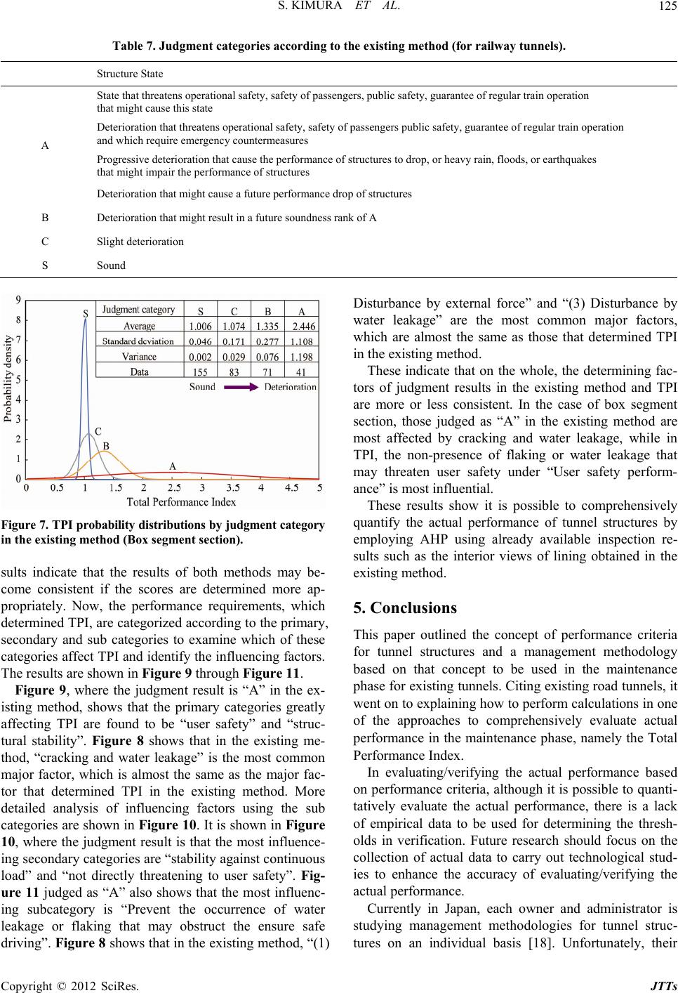 S. KIMURA ET AL. Copyright © 2012 SciRes. JTTs 125 Table 7. Judgment categories acc or ding to the existing method (for railway tunnels). Structure State State that threatens operational safety, safety of passengers, public safety, guarantee of regular train operation that might cause this state Deterioration that threatens operational safety, safety of passengers public safety, guarantee of regular train operation and which requir e emergency countermeasur es Progressive deterioration that cause the performance of structures to drop, or heavy rain, floods, or earthquakes that might impair the performance of structures A Deterioration that might cause a future perform ance drop of structures B Deterioration that might resul t in a future soundness rank of A C Slight deterioration S Sound Figure 7. TPI probability distributions by judgment cate gory in the existing method (Box segment section). sults indicate that the results of both methods may be- come consistent if the scores are determined more ap- propriately. Now, the performance requirements, which determined TPI, are categorized according to the primary, secondary and sub categories to examine which of these categories affect TPI and identify the influencing factors. The results are shown in Figure 9 through Fi gure 11. Figure 9, where the judgment result is “A” in the ex- isting method, shows that the primary categories greatly affecting TPI are found to be “user safety” and “struc- tural stability”. Figure 8 shows that in the existing me- thod, “cracking and water leakage” is the most common major factor, which is almost the same as the major fac- tor that determined TPI in the existing method. More detailed analysis of influencing factors using the sub categories are shown in Figure 10. It is shown in Figure 10, where the judgment result is that the most influence- ing secondary categories are “stability against continuou s load” and “not directly threatening to user safety”. Fig- ure 11 judged as “A” also shows that the most influenc- ing subcategory is “Prevent the occurrence of water leakage or flaking that may obstruct the ensure safe driving”. Figure 8 shows that in the existing method, “(1) Disturbance by external force” and “(3) Disturbance by water leakage” are the most common major factors, which are almost the same as those that determined TPI in the existing method. These indicate that on the whole, the determining fac- tors of judgment results in the existing method and TPI are more or less consistent. In the case of box segment section, those judged as “A” in the existing method are most affected by cracking and water leakage, while in TPI, the non-presence of flaking or water leakage that may threaten user safety under “User safety perform- ance” is most influential. These results show it is possible to comprehensively quantify the actual performance of tunnel structures by employing AHP using already available inspection re- sults such as the interior views of lining obtained in the existing method. 5. Conclusions This paper outlined the concept of performance criteria for tunnel structures and a management methodology based on that concept to be used in the maintenance phase for existing tunnels. Citing existing road tunnels, it went on to explaining how to perform calculations in one of the approaches to comprehensively evaluate actual performance in the maintenance phase, namely the Total Performance Index. In evaluating/verifying the actual performance based on performance criteria, although it is po ssible to quanti- tatively evaluate the actual performance, there is a lack of empirical data to be used for determining the thresh- olds in verification. Future research should focus on the collection of actual data to carry out technological stud- ies to enhance the accuracy of evaluating/verifying the actual performance. Currently in Japan, each owner and administrator is studying management methodologies for tunnel struc- tures on an individual basi [18]. Unfortunately, their s 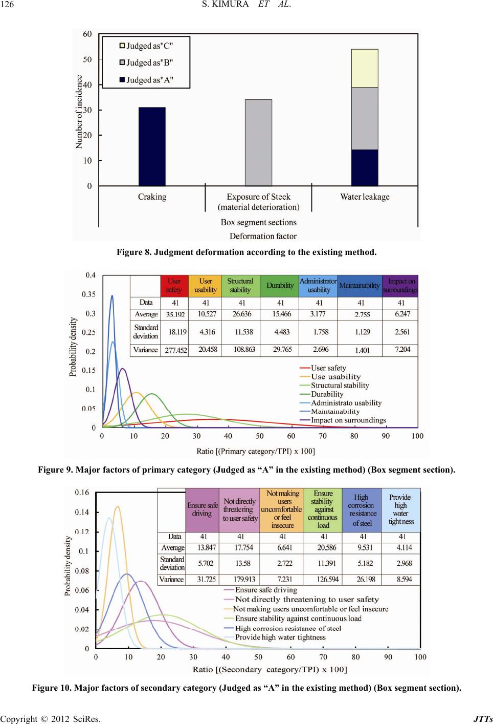 S. KIMURA ET AL. 126 Figure 8. Judgment deformation according to the existing method. Figure 9. Major factors of primary category (Judged as “A” in the existing method) (Box segment section). Figure 10. Major factors of secondary category (Judged as “A” in the existing method) (Box segment section). Copyright © 2012 SciRes. JTTs 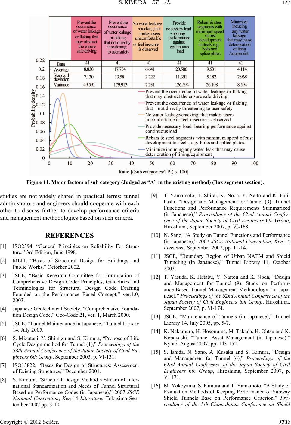 S. KIMURA ET AL. 127 Figure 11. Major factors of sub category (Judged as “A” in the existing method) (Box segment section). studies are not widely shared in practical terms; tunnel administrators and engineers should cooperate with each other to discuss further to develop performance criteria and management methodologies based on such criteria. REFERENCES [1] ISO2394, “General Principles on Reliability For Struc- ture,” 3rd Edition, June 1998. [2] MLIT, “Basis of Structural Design for Buildings and Public Works,” Octorber 2002. [3] JSCE, “Basic Research Committee for Formulation of Comprehensive Design Code: Principles, Guidelines and Terminologies for Structural Design Code Drafting Founded on the Performance Based Concept,” ver.1.0, 2003. [4] Japanese Geotechnical Society, “Comprehensive Founda- tion Design Code,” Geo-Code 21, ver. 1, March 2000. [5] JSCE, “Tunnel Maintenance in Japanese,” Tunnel Library 14, July 2005. [6] S. Mizutani, Y. Shimizu and S. Kimura, “Propose of Life Cycle Design method for Tunnel (1),” Proceedings of the 58th Annual Conference of the Japan Society of Civil En- gineers 6th Group, September 2003, p. VI-131. [7] ISO13822, “Bases for Design of Structures: Assessment of Existing Structures,” December 2001. [8] S. Kimura, “Structural Design Method’s Stream of Inter- national Standardization and Needs of Tunnel Structural Based on Performance Codes (in Japanese),” 2007 JSCE National Convention, Ken-14 Literature, Tokusima Sep- tember 2007 pp. 3-10. [9] T. Yamamoto, T. Shirai, K. Noda, Y. Naito and K. Fuji- hashi, “Design and Management for Tunnel (3): Tunnel Functions and Performance Requirements Summarized (in Japanese),” Proceedings of the 62nd Annual Confer- ence of the Japan Society of Civil Engineers 6th Group, Hiroshima, September 2007, p. Ⅵ-168. [10] N. Sano, “A Study on Tunnel Functions and Performance (in Japanese),” 2007 JSCE National Convention, Ken-14 literature, September 2007, pp. 11-14. [11] JSCE, “Boundary Region of Urban NATM and Shield Tunneling (in Japanese),” Tunnel Library 11, October 2003. [12] T. Yasuda, K. Hatabu, Y. Naitou and K. Noda, “Design and Management for Tunnel (9): Study on Perform- ance-Based Tunnel Management Methodology (in Japa- nese),” Proceedings of the 62nd Annual Conference of the Japan Society of Civil Engineers 6th Group, Hiroshima, September 2007, p. Ⅵ-174. [13] JSCE, “Maintenance of Tunnels (in Japanese),” Tunnel Library 14, July 2005, pp. 5-7. [14] K. Nakamura, H. Hosonuma, M. Takada, H. Ohtsu and K. Kobayashi, “Tunnel Asset Management (in Japanese),” Kyoto, August 2007, pp. 143-152. [15] S. Ishida, N. Sano, A. Kusaka and S. Kimura, “Design and Management for Tunnel (6),” Proceedings of the 62nd Annual Conference of the Japan Society of Civil Engineers 6th Group, Hiroshima, September 2007, p. Ⅵ-171. [16] M. Yokoyama, S. Kimura and T. Yamamoto, “A Study of Evaluation Methods of Keeping Performance of Subway Shield Tunnels Base on Performance Criterion,” Pro- ceedings of the 5th China-Japan Conference on Shield Copyright © 2012 SciRes. JTTs 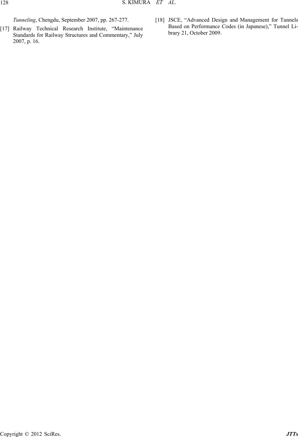 S. KIMURA ET AL. 128 Tunneling, Chengdu, September 2007, pp. 267-277. [17] Railway Technical Research Institute, “Maintenance Standards for Railway Structures and Commentary,” July 2007, p. 16. [18] JSCE, “Advanced Design and Management for Tunnels Based on Performance Codes (in Japanese),” Tunnel Li- brary 21, October 2009. Copyright © 2012 SciRes. JTTs |