Paper Menu >>
Journal Menu >>
 Int. J. Communications, Network and System Sciences, 2010, 3, 477-482 doi:10.4236/ijcns.2010.35064 Published Online May 2010 (http://www.SciRP.org/journal/ijcns/) Copyright © 2010 SciRes. IJCNS Research on Access Network Intrusion Detection System Based on DMT Technology Lingxi Wu, Jie Zhan, Qiange He, Shuiyan He Hunan University of Science and Technology, Xiangtan, China E-mail: lxwhsy@126.com Received January 19, 2010; revised March 1, 2010; accepted April 7, 2010 Abstract Analysis is done on the inter-carrier interference (ICI) that caused by multi-carrier communication system frequency offset. The application model of DFT/IDFT in ADSL access network is analyzed further; the hardware detection and software analysis scheme of the system are proposed for the accessing network. Ex- periments have proved that monitoring system can filter the network data flow and carry on statistical and analysis, achieving real-time monitoring. Keywords: DMT, ICI, Intrusion Detection, DFT/IDFT 1. Introduction The Discrete Multi-Tone DMT () technology has been applied successfully on the ADSL (Asymmetric Digital Subscriber Line) transmission system, and has developed the broadband transmission system that based on Twist- Pair. The problems of network detection and monitoring will be inherent in the development of network, yet the rapid development of the network has been ahead of the real-time monitoring. To solve it, data detection system based on DMT technology has been studied systemati- cally, and data acquisition equipment has been devised, which can achieve filtering analysis and statistics of the network data stream with no influence on the user and the phone company end of the line. 2. Multi-carrier Communication System Modeling QAM (Quadrature Amplitude Modulation) is the basis of DMT, Model use multiple QAM constellation diagram encoders, and each constellation diagram encoder use a different carrier frequency, The DMT code element that were formed by summing all the carries transmitted through the channel. If the receiver can separate sine waves from cosine waves on different frequencies, each wave can be decoded independently, the method of en- coded and decoded are consist with the QAM signals; to ensure no interference from f1 to fn sub-channel, we must make sure that a sine and cosine wave in one sub-chan- nel are orthogonality with any other sub-channels, and its formula is as follow [1,2]: 0cos() cos()0 Tnt mtdt 0cos( )sin()0 Tnt mtdt 0sin( )sin()0 Tnt mtdt n and m are unequal integers, and ω is the base rate. By the expression of orthogonality, we concluded the each sub-channel frequency must be an integral multiple of base frequency, and the code element period T is re- ciprocal of the base frequency or an integral multiple of the reciprocal of the base frequency. Two situations wo- uld appear: First, the frequency offset is an integral mul- tiple of sub-carrier; second, the frequency offset is not an integral multiple of sub-carriers; both of two situations will make system characteristics deteriorate. Assuming the number of carrier is limited, Figure 1 is a block diagram of a DMT communication system model [3], and ac- cording to the system, we make the following discussion: During the ‘i’ symbol cycle, Assuming the original data symbol is{a0,i, a1,i ,…, an-1,i}, after IDFT calculate, we can get: 1 ,, 0 12 exp N ki li l jlk ba NN (1) Therefore, we can get the output signal x(t) as follow: 1 , 0 x( )exp(2) N cki k kT tjftbpt N (2) 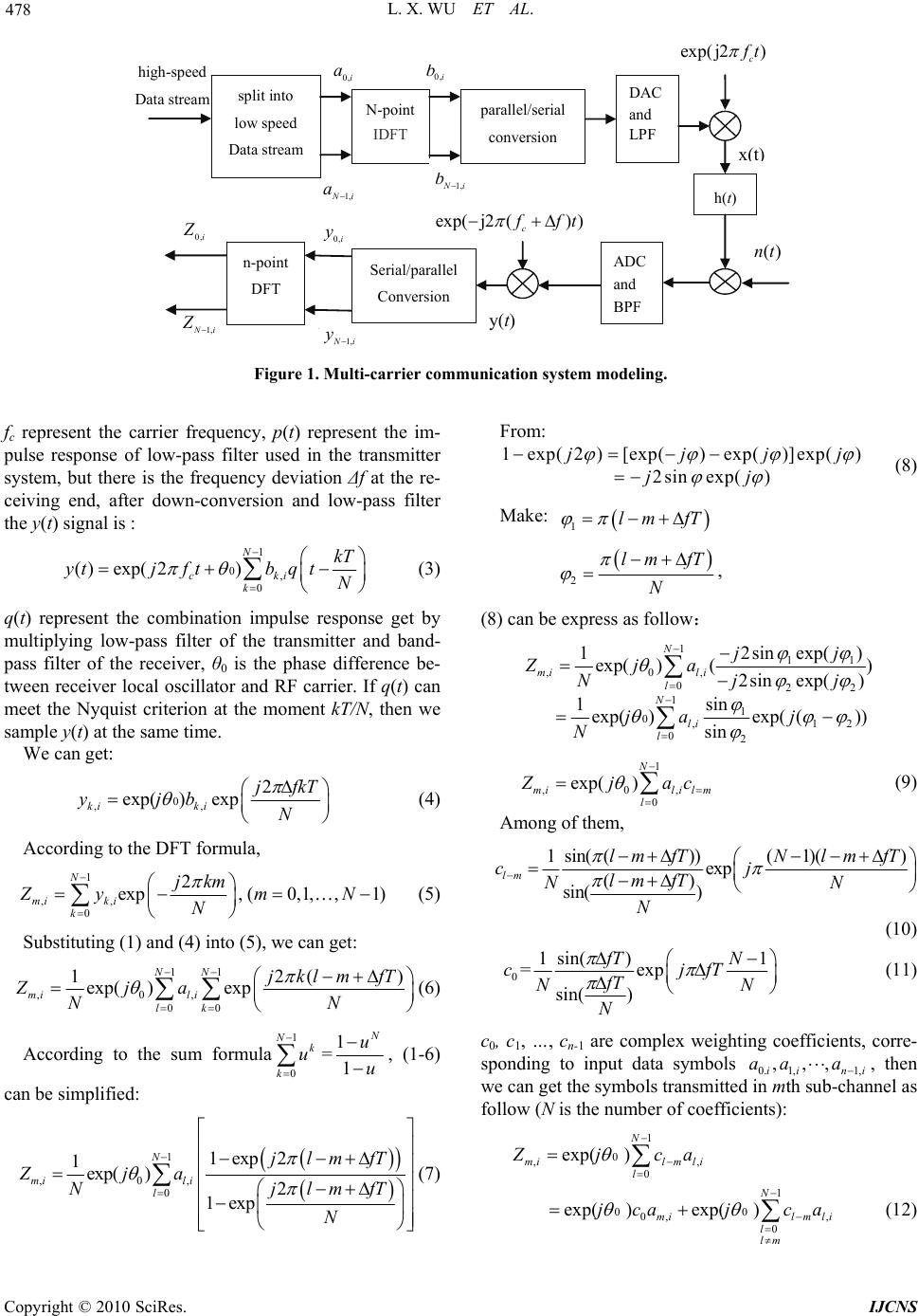 L. X. WU ET AL. Copyright © 2010 SciRes. IJCNS 478 x ( t ) h(t) exp(-j2π( f c + Δf ) t ) ADC and BPF z N-1,i z 0,i b 0,i a 0,i b N-1,i a N-1,i y N 1 i y 0,i y(t) n-point DFT high-speed Data stream split into low speed Data stream N-point IDFT parallel/serial conversion DAC and LP F Serial/parallel Conversion n( t ) 0,i a 0,i b 1, N i a 1, N i b exp( j2) c f t exp(j2() ) c f ft 0,i Z 0,i y 1, N i Z 1, N i y ()nt Figure 1. Multi-carrier communication system modeling. fc represent the carrier frequency, p(t) represent the im- pulse response of low-pass filter used in the transmitter system, but there is the frequency deviation Δf at the re- ceiving end, after down-conversion and low-pass filter the y(t) signal is : 1 0, 0 ()exp( 2) N cki k kT ytjftbq tN (3) q(t) represent the combination impulse response get by multiplying low-pass filter of the transmitter and band- pass filter of the receiver, θ0 is the phase difference be- tween receiver local oscillator and RF carrier. If q(t) can meet the Nyquist criterion at the moment kT/N, then we sample y(t) at the same time. We can get: 0 ,, 2 exp( )exp ki ki jfkT yjb N (4) According to the DFT formula, 1 ,, 0 2 exp, (0,1,,1) N mi ki k jkm Zym N N (5) Substituting (1) and (4) into (5), we can get: 11 ,0, 00 12() exp( )exp NN mi li lk jklm fT Zja NN (6) According to the sum formula 1 0 Nk k u =1 1 N u u , (1-6) can be simplified: 1 ,0, 0 1exp 2 1exp( )2 1exp N mi li l jlmfT Zja NjlmfT N (7) From: 1exp( 2)[exp()exp()]exp() 2sin exp() jjjj jj (8) Make: 1lm fT 2 lm fT N , (8) can be express as follow: 1 11 ,0, 022 1 1 0,12 02 2sin exp() 1exp( )() 2sin exp() sin 1exp()exp( ()) sin N mi li l N li l jj Zja Njj ja j N 1 ,0, 0 exp( ) N mililm l Z jac (9) Among of them, 1sin(())(1)( ) exp () sin( ) lm lm fTNlm fT cj lm fT NN N (10) 0 1 sin()1 =exp sin( ) f TN cjfT fT NN N (11) c0, c1, …, cn-1 are complex weighting coefficients, corre- sponding to input data symbols 0. 1,1, ,,, ii ni aa a , then we can get the symbols transmitted in mth sub-channel as follow (N is the number of coefficients): 1 0 ,, 0 exp( ) N milmli l Z jca 1 00 0, , 0 exp( )exp( ) N mil mli l lm jcaj ca (12) 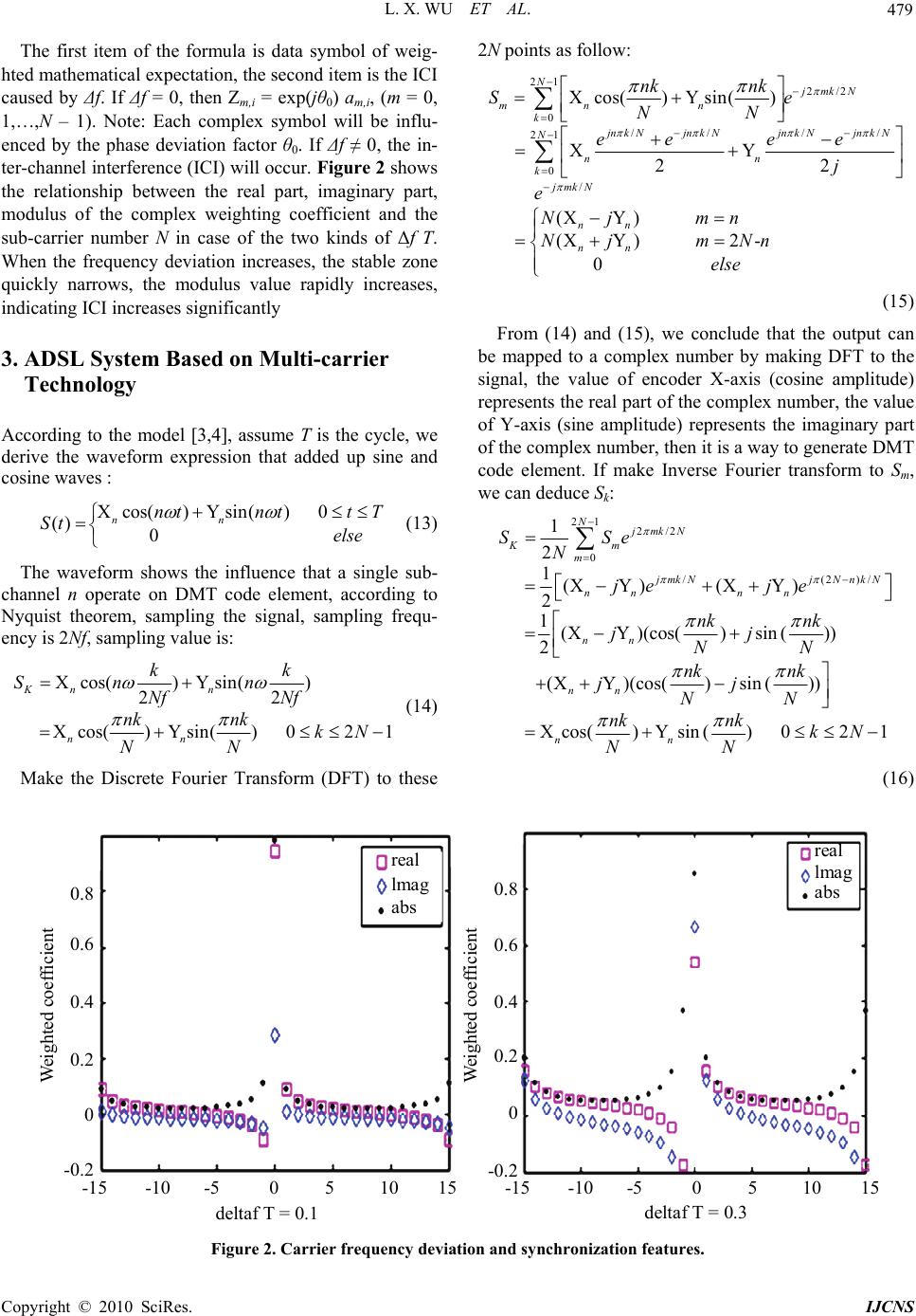 L. X. WU ET AL. Copyright © 2010 SciRes. IJCNS 479 The first item of the formula is data symbol of weig- hted mathematical expectation, the second item is the ICI caused by Δf. If Δf = 0, then Zm,i = exp(jθ0) am,i, (m = 0, 1,…,N – 1). Note: Each complex symbol will be influ- enced by the phase deviation factor θ0. If Δf ≠ 0, the in- ter-channel interference (ICI) will occur. Figure 2 shows the relationship between the real part, imaginary part, modulus of the complex weighting coefficient and the sub-carrier number N in case of the two kinds of Δf T. When the frequency deviation increases, the stable zone quickly narrows, the modulus value rapidly increases, indicating ICI increases significantly 3. ADSL System Based on Multi-carrier Technology According to the model [3,4], assume T is the cycle, we derive the waveform expression that added up sine and cosine waves : Xcos()Ysin()0 () 0 nn ntntt T St else (13) The waveform shows the influence that a single sub- channel n operate on DMT code element, according to Nyquist theorem, sampling the signal, sampling frequ- ency is 2Nf, sampling value is: Xcos()Ysin() 22 Xcos()Ysin()021 Kn n nn kk Sn n Nf Nf nknk kN NN (14) Make the Discrete Fourier Transform (DFT) to these 2N points as follow: 21 2/2 0 // // 21 0 / Xcos()Ysin() XY 22 (XY) (XY)2- 0 NjmkN mn n k jnk Njnk Njn k Njn k N N nn k jmkN nn nn nk nk Se NN ee ee j e Nj mn Nj mNn else (15) From (14) and (15), we conclude that the output can be mapped to a complex number by making DFT to the signal, the value of encoder X-axis (cosine amplitude) represents the real part of the complex number, the value of Y-axis (sine amplitude) represents the imaginary part of the complex number, then it is a way to generate DMT code element. If make Inverse Fourier transform to Sm, we can deduce Sk: 21 2/2 0 /(2)/ 1 2 1(XY )(XY ) 2 1(XY)(cos()sin ()) 2 (XY)(cos()sin()) Xcos() Ysin()021 NjmkN Km m jmkNjN nkN nn nn nn nn nn SSe N je je nk nk jj NN nk nk jj NN nknk kN NN (16) real lmag abs real lmag abs 0.8 0.6 0.4 0.2 0 -0.2 0.8 0.6 0.4 0.2 0 -0.2 -15 -10 -5 0 5 10 15 deltaf T = 0.1 deltaf T = 0.3 Weighted coefficient Weighted coefficient -15 -10 -5 0 5 10 1 5 Figure 2. Carrier frequency deviation and synchronization features. 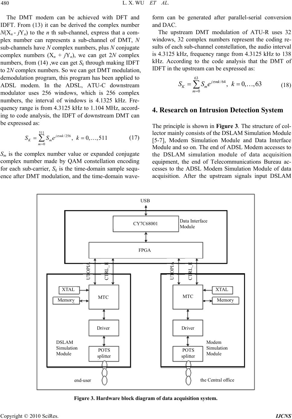 L. X. WU ET AL. Copyright © 2010 SciRes. IJCNS 480 The DMT modem can be achieved with DFT and IDFT. From (13) it can be derived the complex number N(Xn - jYn) to the n th sub-channel, express that a com- plex number can represents a sub-channel of DMT, N sub-channels have N complex numbers, plus N conjugate complex numbers (Xn + jYn), we can get 2N complex numbers, from (14) ,we can get Sk through making IDFT to 2N complex numbers. So we can get DMT modulation, demodulation program, this program has been applied to ADSL modem. In the ADSL, ATU-C downstream modulator uses 256 windows, which is 256 complex numbers, the interval of windows is 4.1325 kHz. Fre- quency range is from 4.3125 kHz to 1.104 MHz, accord- ing to code analysis, the IDFT of downstream DMT can be expressed as: 511 /256 0 ,0, ,511 jmk Km m SSe k (17) Sm is the complex number value or expanded conjugate complex number made by QAM constellation encoding for each sub-carrier, Sk is the time-domain sample sequ- ence after DMT modulation, and the time-domain wave- form can be generated after parallel-serial conversion and DAC. The upstream DMT modulation of ATU-R uses 32 windows, 32 complex numbers represent the coding re- sults of each sub-channel constellation, the audio interval is 4.3125 kHz, frequency range from 4.3125 kHz to 138 kHz. According to the code analysis that the DMT of IDFT in the upstream can be expressed as: 63 /64 0 ,0,,63 jmk Km m SSe k (18) 4. Research on Intrusion Detection System The principle is shown in Figure 3. The structure of col- lector mainly consists of the DSLAM Simulation Module [5-7], Modem Simulation Module and Data Interface Module and so on. The end of ADSL Modem accesses to the DSLAM simulation module of data acquisition equipment, the end of Telecommunications Bureau ac- cesses to the ADSL Modem Simulation Module of data acquisition. After the upstream signals input DSLAM USB CY7C68001 Data Interface Module FPGA MTC MTC Driver Driver POTS splitter POTS splitt er XTAL XTAL Memor y Memor y Modem Simulation Module DSLAM Simulation Module the Central office end-user UTOPIA CTRL_E UTOPIA CTRL_E Figure 3. Hardware block diagram of data acquisition system. 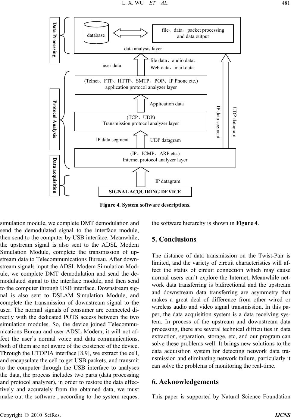 L. X. WU ET AL. Copyright © 2010 SciRes. IJCNS 481 database file 、data、packet processing and data output data analysis layer Protocol Analysis datagram IP data segment (Telnet、FTP、HTTP、SMTP、POP、IP Phone etc.) application protocol analyzer layer (TCP,UDP) Transmission protocol analyzer layer (IP、ICMP、ARP etc.) Internet protocol analyzer layer SIGNAL ACQUIRING DEVICE IP datagram file data、audio data、 Web data、mail data user data data segment UDP datagram A pplication data Data Processing data acquisition database data analysis layer file、data、packet processing and data output file data、audio data、 Web data、mail data user data (Telnet、FTP、HTTP、SMTP、POP、IP Phone etc.) application protocol analyzer layer Application data (TCP、UDP) Transmission protocol analyzer layer UDP datagram IP data segment (IP、ICM P 、ARP etc.) Internet protocol analyzer layer IP datagram SIGNAL ACQUIRING DEVICE IP data segment Data Processing UDP datagram Protocol Analysis Data acquisition Figure 4. System software descriptions. simulation module, we complete DMT demodulation and send the demodulated signal to the interface module, then send to the computer by USB interface. Meanwhile, the upstream signal is also sent to the ADSL Modem Simulation Module, complete the transmission of up- stream data to Telecommunications Bureau. After down- stream signals input the ADSL Modem Simulation Mod- ule, we complete DMT demodulation and send the de- modulated signal to the interface module, and then send to the computer through USB interface. Downstream sig- nal is also sent to DSLAM Simulation Module, and complete the transmission of downstream signal to the user. The normal signals of consumer are connected di- rectly with the dedicated POTS access between the two simulation modules. So, the device joined Telecommu- nications Bureau and user ADSL Modem, it will not af- fect the user’s normal voice and data communications, both of them are not aware of the existence of the device. Through the UTOPIA interface [8,9], we extract the cell, and encapsulate the cell to get USB packets, and transmit to the computer through the USB interface to analyses the data, the process includes two parts (data processing and protocol analyzer), in order to restore the data effec- tively and accurately from the obtained data, we must make out the software , according to the system request the software hierarchy is shown in Figure 4. 5. Conclusions The distance of data transmission on the Twist-Pair is limited, and the variety of circuit characteristics will af- fect the status of circuit connection which may cause normal users can’t explore the Internet, Meanwhile net- work data transferring is bidirectional and the upstream and downstream data transferring are asymmetry that makes a great deal of difference from other wired or wireless audio and video signal transmission. In this pa- per, the data acquisition system is a data receiving sys- tem. In process of the upstream and downstream data processing, there are several technical difficulties in data extraction, separation, storage, etc, and our program can solve these problems well. It brings new solutions to the data acquisition system for detecting network data tra- nsmission and eliminating network failure, particularly it can solve the problems of monitoring the real-time. 6. Acknowledgements This paper is supported by Natural Science Foundation  L. X. WU ET AL. Copyright © 2010 SciRes. IJCNS 482 of Hunan Provincial, China (Grant No. 07JJ6128). 7. References [1] W. Stallings, “Data and Computer Communications,” Prentice Hall Upper Saddle River, New Jersey, 2000. [2] T. Pollet and M. Moeneclaey, “Synchronization of OF- DM Signals,” IEEE Globecom’95, Singapore, Vol. 3, No- vember 1995, pp. 2054-2058. [3] H. V. Poor, “Iterative Multiuser Detection,” IEEE Singal Processing Magazine, Vol. 21, No. 1, 2004, pp. 81-88. [4] “ITU-T Recommendation G.992.3, Asymmetric digital subscriber line transceivers2 (ADSL2),” July 2002. [5] J. Heinanen, “RFC1483: Multi-protocol Encapsulation over ATM Adaptation Layer 5,” RFC Editor, United States, 1993. [6] L. X. Wu, Z. P. Huang, G. L. Tang and L. Y. Pan, “Design and Realization of Data Acquisition Access Circuit Based on ATM Network,” Telecommunication Engineering, Vol. 44, No. 6, 2004, pp. 107-110. [7] AFE-20154 Data Sheet rev.1- June 1999. [8] L. X. Wu and T. F. Jiang, “Research and Aealization of Real-time Data Acquisition System Based on ADSL Acc- ess Network,” Engineering Journal of Wuhan Uni- versity, Vol. 39, No. 6, 2006, pp. 113-116. [9] “CY7C68001 EZ-USB SX2™ High-Speed USB Inter- face Device,” Cypress Semiconductor Corporation, July 2003, pp. 1-50. |