Paper Menu >>
Journal Menu >>
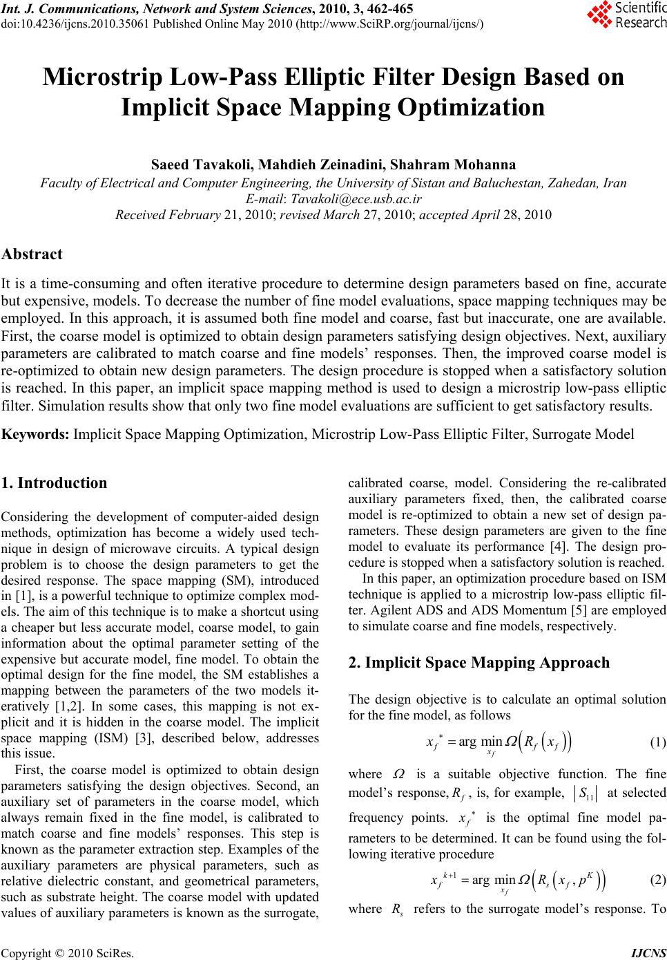 Int. J. Communications, Network and System Sciences, 2010, 3, 462-465 doi:10.4236/ijcns.2010.35061 Published Online May 2010 (http://www.SciRP.org/journal/ijcns/) Copyright © 2010 SciRes. IJCNS Microstrip Low-Pass Elliptic Filter Design Based on Implicit Space Mapping Optimization Saeed Tavakoli, Mahdieh Zeinadini, Shahram Mohanna Faculty of Electrical and Computer Engineering, the University of Sistan and Baluchestan, Zahedan, Iran E-mail: Tavakoli@ece.usb.ac.ir Received February 21, 2010; revised March 27, 2010; accepted April 28, 2010 Abstract It is a time-consuming and often iterative procedure to determine design parameters based on fine, accurate but expensive, models. To decrease the number of fine model evaluations, space mapping techniques may be employed. In this approach, it is assumed both fine model and coarse, fast but inaccurate, one are available. First, the coarse model is optimized to obtain design parameters satisfying design objectives. Next, auxiliary parameters are calibrated to match coarse and fine models’ responses. Then, the improved coarse model is re-optimized to obtain new design parameters. The design procedure is stopped when a satisfactory solution is reached. In this paper, an implicit space mapping method is used to design a microstrip low-pass elliptic filter. Simulation results show that only two fine model evaluations are sufficient to get satisfactory results. Keywords: Implicit Space Mapping Optimization, Microstrip Low-Pass Elliptic Filter, Surrogate Model 1. Introduction Considering the development of computer-aided design methods, optimization has become a widely used tech- nique in design of microwave circuits. A typical design problem is to choose the design parameters to get the desired response. The space mapping (SM), introduced in [1], is a powerful technique to optimize complex mod- els. The aim of this technique is to make a shortcut using a cheaper but less accurate model, coarse model, to gain information about the optimal parameter setting of the expensive but accurate model, fine model. To obtain the optimal design for the fine model, the SM establishes a mapping between the parameters of the two models it- eratively [1,2]. In some cases, this mapping is not ex- plicit and it is hidden in the coarse model. The implicit space mapping (ISM) [3], described below, addresses this issue. First, the coarse model is optimized to obtain design parameters satisfying the design objectives. Second, an auxiliary set of parameters in the coarse model, which always remain fixed in the fine model, is calibrated to match coarse and fine models’ responses. This step is known as the parameter extraction step. Examples of the auxiliary parameters are physical parameters, such as relative dielectric constant, and geometrical parameters, such as substrate height. The coarse model with updated values of auxiliary parameters is known as the surrogate, calibrated coarse, model. Considering the re-calibrated auxiliary parameters fixed, then, the calibrated coarse model is re-optimized to obtain a new set of design pa- rameters. These design parameters are given to the fine model to evaluate its performance [4]. The design pro- cedure is stopped when a satisfactory solution is reached. In this paper, an optimization procedure based on ISM technique is applied to a microstrip low-pass elliptic fil- ter. Agilent ADS and ADS Momentum [5] are employed to simulate coarse and fine models, respectively. 2. Implicit Space Mapping Approach The design objective is to calculate an optimal solution for the fine model, as follows arg min f fff x x Rx (1) where is a suitable objective function. The fine model’s response, f R, is, for example, 11 S at selected frequency points. f x is the optimal fine model pa- rameters to be determined. It can be found using the fol- lowing iterative procedure 1arg min, f kK fsf x xRxp (2) where s R refers to the surrogate model’s response. To 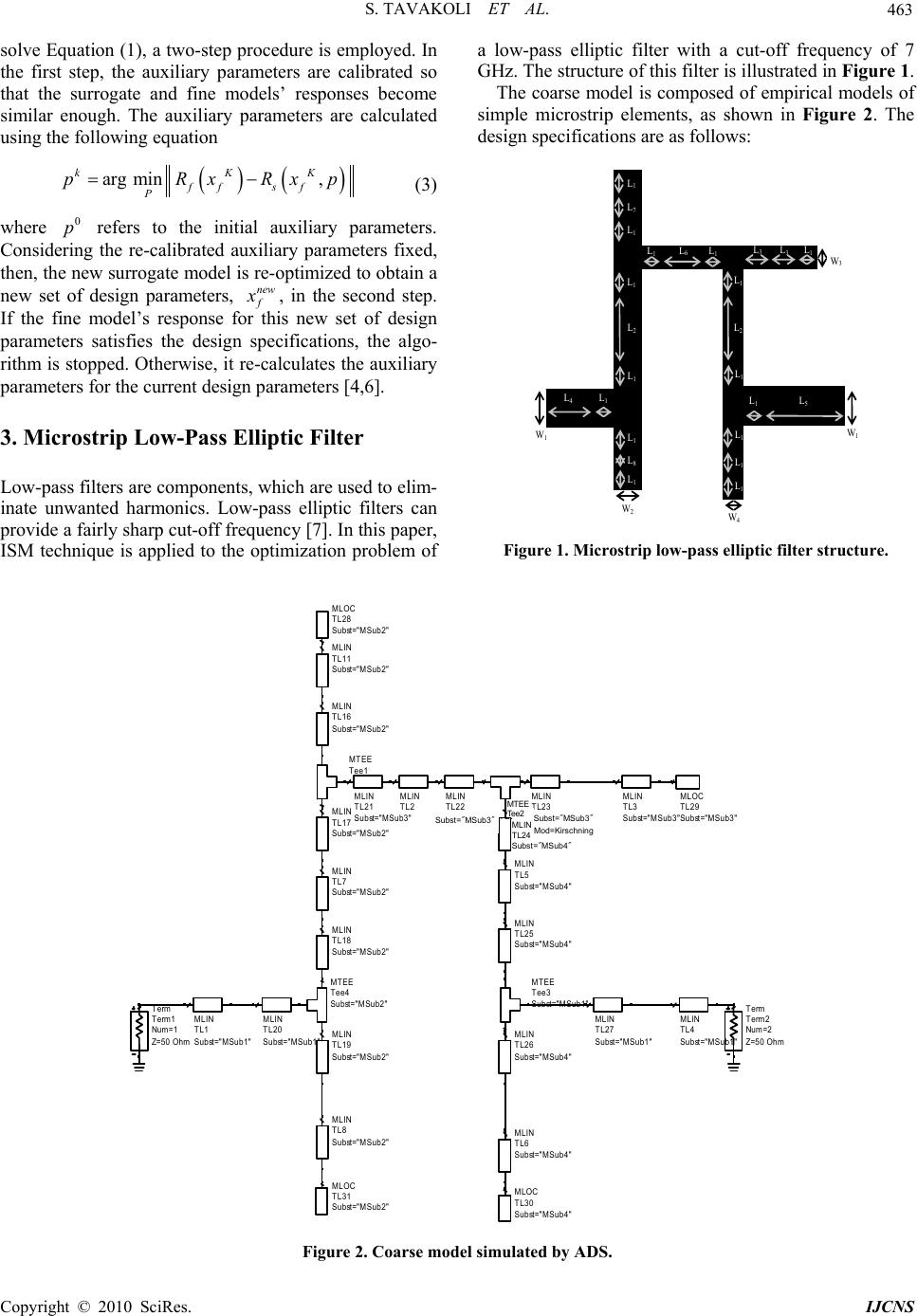 S. TAVAKOLI ET AL. Copyright © 2010 SciRes. IJCNS 463 solve Equation (1), a two-step procedure is employed. In the first step, the auxiliary parameters are calibrated so that the surrogate and fine models’ responses become similar enough. The auxiliary parameters are calculated using the following equation arg min, kKK ff sf P pRxRxp (3) where 0 p refers to the initial auxiliary parameters. Cons ider in g the re-calibrated auxiliary parameters fixed, then, the new surrogate model is re-optimized to obtain a new set of design parameters, new f x , in the second step. If the fine model’s response for this new set of design parameters satisfies the design specifications, the algo- rithm is stopped. Otherwise, it re-calculates the auxiliary parameters for the current design parameters [4,6]. 3. Microstrip Low-Pass Elliptic Filter Low-pass filters are components, which are used to elim- inate unwanted harmonics. Low-pass elliptic filters can provide a fairly sharp cut-off frequency [7]. In this paper, ISM technique is applied to the optimization problem of a low-pass elliptic filter with a cut-off frequency of 7 GHz. The structure of this filter is illustrated in Figure 1. The coarse model is composed of empirical models of simple microstrip elements, as shown in Figure 2. The design specifications are as follows: L 1 L 7 W 3 W 1 W 1 W 2 W 4 L 1 L 1 L 1 L 2 L 1 L 8 L 1 L 1 L 4 L 1 L 1 L 6 L 1 L 3 L 3 L 1 L 2 L 1 L 1 L 5 L 1 L 1 L 1 Figure 1. Microstrip low-pass elliptic filter structure. MLOC TL30 Subst="MSub4" MLIN TL6 Subst="MSub4" MLIN TL26 Subst="MSub4" MLIN TL4 Subst="MSub1" MLIN TL27 Subst="MSub1" MLIN TL25 Subst="MSub4" MTEE Tee3 Subst="MSub1" MLIN TL5 Subst="MSub4" MLOC TL29 Subst="MSub3" MLIN TL3 Subst="MSub3" MLIN TL23 Mod=Kirschning Subst="MSub3" MLIN TL24 Subst="MSub4" MTEE Tee2 MLIN TL22 Subst="MSub3" MLIN TL2 MLIN TL21 Subst="MSub3" MLOC TL28 Subst="MSub2" MLIN TL11 Subst="MSub2" MLIN TL16 Subst="MSub2" MTEE Tee1 MLIN TL17 Subst="MSub2" MLIN TL7 Subst="MSub2" MTEE Tee4 Subst="MSub2" MLIN TL18 Subst="MSub2" MLIN TL19 Subst="MSub2" MLIN TL8 Subst="MSub2" MLOC TL31 Subst="MSub2" MLIN TL20 Subst="MSub1" MLIN TL1 Subst="MSub1" Term Term2 Z=50 Ohm Num=2 Term Term1 Z=50 Ohm Num=1 Subst="MSub3" MLIN TL24 Subst="MSub4" Mod=Kirschning Subst="MSub3" MTEE Tee2 Figure 2. Coarse model simulated by ADS. 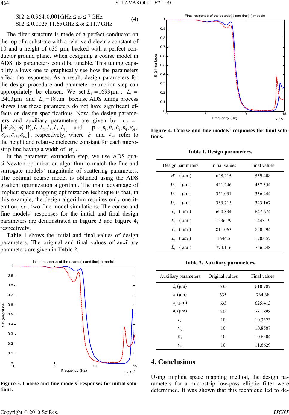 S. TAVAKOLI ET AL. Copyright © 2010 SciRes. IJCNS 464 |S12 |0.964,0.001GHz7 GHz |S12 |0.0025,11.65GHz11.7 GHz (4) The filter structure is made of a perfect conductor on the top of a substrate with a relative dielectric constant of 10 and a height of 635 µm, backed with a perfect con- ductor ground plane. When designing a coarse model in ADS, its parameters could be tunable. This tuning capa- bility allows one to graphically see how the parameters affect the responses. As a result, design parameters for the design procedure and parameter extraction step can appropriately be chosen. We set41693 mL, 5 L 2403 m and 818 mL because ADS tuning process shows that these parameters do not have significant ef- fects on design specifications. Now, the design parame- ters and auxiliary parameters are given by f x 123412367 ,,,,,,,,WWWWL LLLLand 1234 1 p [, ,, ,, r hhhh 234 ,,] rrr , respectively, where i h and ri ε refer to the height and relative dielectric constant for each micro- strip line having a width of i W. In the parameter extraction step, we use ADS qua- si-Newton optimization algorithm to match the fine and surrogate models’ magnitude of scattering parameters. The optimal coarse model is obtained using the ADS gradient optimization algorithm. The main advantage of implicit space mapping optimization technique is that, in this example, the design algorithm requires only one it- eration, i.e., two fine model simulations. The coarse and fine models’ responses for the initial and final design parameters are demonstrated in Figure 3 and Figure 4, respectively. Table 1 shows the initial and final values of design parameters. The original and final values of auxiliary parameters are given in Table 2. 05 10 1 5 x 10 9 0 0.1 0.2 0.3 0.4 0.5 0.6 0.7 0.8 0.9 1 Frequency (Hz) S12 (magnitude) Initial response of the coarse(-) and fine(--) models Figure 3. Coarse and fine models’ responses for initial solu- tions. 05 10 1 5 x 10 9 0 0.1 0.2 0.3 0.4 0.5 0.6 0.7 0.8 0.9 1 Frequency (Hz) S12 (magnitude ) Final response of the coarse(-) and fine(--) models Figure 4. Coarse and fine models’ responses for final solu- tions. Table 1. Design parameters. Design parameters Initial values Final values 1 W ( m ) 638.215 559.408 2 W ( m ) 421.246 437.354 3 W ( m ) 351.031 336.444 4 W ( m ) 333.715 343.167 1 L ( m ) 690.834 647.674 2 L ( m ) 1536.79 1443.19 3 L ( m ) 811.063 820.294 6 L ( m ) 1646.5 1705.57 7 L ( m ) 774.116 766.248 Table 2. Auxiliary parameters. Auxiliary parametersOriginal values Final values 1(m)h 635 610.787 2(m)h 635 764.68 3(m)h 635 625.413 4(m)h 635 781.898 1r 10 10.3323 2r 10 10.8587 3r 10 10.6504 4r 10 11.6629 4. Conclusions Using implicit space mapping method, the design pa- rameters for a microstrip low-pass elliptic filter were determined. It was shown that this technique led to de- 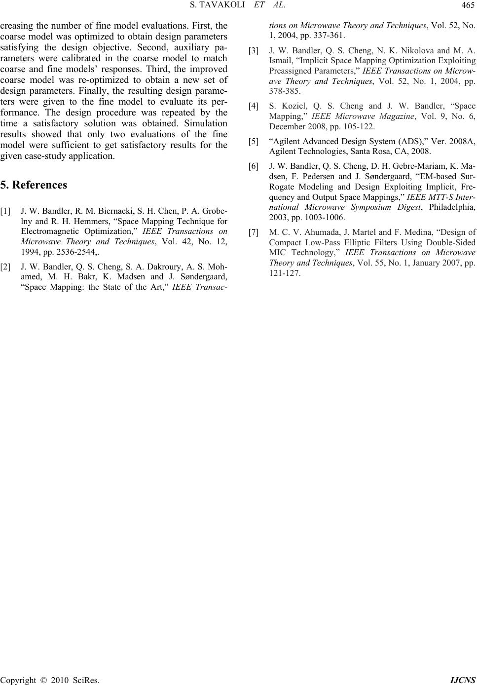 S. TAVAKOLI ET AL. Copyright © 2010 SciRes. IJCNS 465 creasing the number of fine model evaluations. First, the coarse model was optimized to obtain design parameters satisfying the design objective. Second, auxiliary pa- rameters were calibrated in the coarse model to match coarse and fine models’ responses. Third, the improved coarse model was re-optimized to obtain a new set of design parameters. Finally, the resulting design parame- ters were given to the fine model to evaluate its per- formance. The design procedure was repeated by the time a satisfactory solution was obtained. Simulation results showed that only two evaluations of the fine model were sufficient to get satisfactory results for the given case-study application. 5. References [1] J. W. Bandler, R. M. Biernacki, S. H. Chen, P. A. Grobe- lny and R. H. Hemmers, “Space Mapping Technique for Electromagnetic Optimization,” IEEE Transactions on Microwave Theory and Techniques, Vol. 42, No. 12, 1994, pp. 2536-2544,. [2] J. W. Bandler, Q. S. Cheng, S. A. Dakroury, A. S. Moh- amed, M. H. Bakr, K. Madsen and J. Søndergaard, “Space Mapping: the State of the Art,” IEEE Transac- tions on Microwave Theory and Techniques, Vol. 52, No. 1, 2004, pp. 337-361. [3] J. W. Bandler, Q. S. Cheng, N. K. Nikolova and M. A. Ismail, “Implicit Space Mapping Optimization Exploiting Preassigned Parameters,” IEEE Transactions on Microw- ave Theory and Techniques, Vol. 52, No. 1, 2004, pp. 378-385. [4] S. Koziel, Q. S. Cheng and J. W. Bandler, “Space Mapping,” IEEE Microwave Magazine, Vol. 9, No. 6, December 2008, pp. 105-122. [5] “Agilent Advanced Design System (ADS),” Ver. 2008A, Agilent Technologies, Santa Rosa, CA, 2008. [6] J. W. Bandler, Q. S. Cheng, D. H. Gebre-Mariam, K. Ma- dsen, F. Pedersen and J. Søndergaard, “EM-based Sur- Rogate Modeling and Design Exploiting Implicit, Fre- quency and Output Space Mappings,” IEEE MTT-S Inter- national Microwave Symposium Digest, Philadelphia, 2003, pp. 1003-1006. [7] M. C. V. Ahumada, J. Martel and F. Medina, “Design of Compact Low-Pass Elliptic Filters Using Double-Sided MIC Technology,” IEEE Transactions on Microwave Theory and Techniques, Vol. 55, No. 1, January 2007, pp. 121-127. |