Paper Menu >>
Journal Menu >>
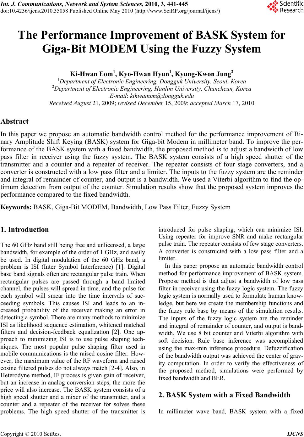 Int. J. Communications, Network and System Sciences, 2010, 3, 441-445 doi:10.4236/ijcns.2010.35058 Published Online May 2010 (http://www.SciRP.org/journal/ijcns/) Copyright © 2010 SciRes. IJCNS The Performance Improvement of BASK System for Giga-Bit MODEM Using the Fuzzy System Ki-Hwan Eom1, Kyo-Hwan Hyun1, Kyung-Kwon Jung2 1Department of Electronic Engineering, Dongguk University, Seoul, Korea 2Department of Electronic Engineering, Hanlim University, Chuncheun, Korea E-mail: kihwanum@dongguk.edu Received August 21, 2009; revised December 15, 2009; accepted March 17, 2010 Abstract In this paper we propose an automatic bandwidth control method for the performance improvement of Bi- nary Amplitude Shift Keying (BASK) system for Giga-bit Modem in millimeter band. To improve the per- formance of the BASK system with a fixed bandwidth, the proposed method is to adjust a bandwidth of low pass filter in receiver using the fuzzy system. The BASK system consists of a high speed shutter of the transmitter and a counter and a repeater of receiver. The repeater consists of four stage converters, and a converter is constructed with a low pass filter and a limiter. The inputs to the fuzzy system are the reminder and integral of remainder of counter, and output is a bandwidth. We used a Viterbi algorithm to find the op- timum detection from output of the counter. Simulation results show that the proposed system improves the performance compared to the fixed bandwidth. Keywords: BASK, Giga-Bit MODEM, Bandwidth, Low Pass Filter, Fuzzy System 1. Introduction The 60 GHz band still being free and unlicensed, a large bandwidth, for example of the order of 1 GHz, and easily be used. In digital modulation of the 60 GHz band, a problem is ISI (Inter Symbol Interference) [1]. Digital base band signals often are rectangular pulse train. When rectangular pulses are passed through a band limited channel, the pulses will spread in time, and the pulse for each symbol will smear into the time intervals of suc- ceeding symbols. This causes ISI and leads to an in- creased probability of the receiver making an error in detecting a symbol. There are many methods to minimize ISI as likelihood sequence estimation, whitened matched filters and decision-feedback equalization [2]. One ap- proach to minimizing ISI is to use pulse shaping tech- niques. The most popular pulse shaping filter used in mobile communications is the raised cosine filter. How- ever, the maximum value of the RF waveform and raised cosine filtered pulses do not always match [2-4]. Also, in Heterodyne method, IF process is given gain of receiver, but an increase in analog conversion steps, the more the price will also increase. The BASK system consists of a high speed shutter and a mixer of the transmitter, and a counter and a repeater of the receiver for solves these problems. The high speed shutter of the transmitter is introduced for pulse shaping, which can minimize ISI. Using repeater for improve SNR and make rectangular pulse train. The repeater consists of few stage converters. A converter is constructed with a low pass filter and a limiter. In this paper propose an automatic bandwidth control method for performance improvement of BASK system. Propose method is that adjust a bandwidth of low pass filter in receiver using the fuzzy logic system. The fuzzy logic system is normally used to formulate human know- ledge, but here we create the membership functions and the fuzzy rule base by means of the simulation results. The inputs of the fuzzy logic system are the reminder and integral of remainder of counter, and output is band- width. We use 8 bit counter and Viterbi algorithm with soft decision. Rule base inference was accomplished using the max-min inference procedure. Defuzzification of the bandwidth output was achieved the center of grav- ity computation. In order to verify the effectiveness of the proposed method, simulations were performed by fixed bandwidth and BER. 2. BASK System with a Fixed Bandwidth In millimeter wave band, BASK system with a fixed  K.-H. EOM ET AL. Copyright © 2010 SciRes. IJCNS 442 bandwidth of Giga-bit MODEM without IF process us- ing high speed shutter for pulse shaping of input signal and minimize ISI in the transmitter, and using repeater for improve SNR and make rectangular pulse train in receiver. Figure 1 shows the block diagram of BASK system with a fixed bandwidth. In the transmitter, RCS is raised cosine signal genera- tor. The transmitter uses a high speed shutter that can truncate the side lobe of the raised cosine filter. A shutter performs switching window. The output of a shutter is given by sin(/ ) (), 1 () 0,0 s s tT tn ht t n (1) Where ()t is a gain for the symbol period, is the roll off factor, t is the time, S T is the symbol pe- riod, and n is the state of the symbol. A shutter func- tion is to make a constant envelope. The receiver uses a repeater without IF (Intermediate Frequency) that consists of two stage converters. A con- verter is constructed with the LPF and the limiter. Design parameters of converters are bandwidth of the LPF (BLPF) and stiffness of the limiter (SL: Stiffest Limiter). The theoretical solution is given by ()( ()) ii ytSL xtG (2) Where () i x tG is the input of the limiter, () i yt is the output of the converter, SL is a transfer function of the limiter. The block diagram of a converter is shown in Figure 2. Pulse train Viterbi Encode r Shutter Mixer LPF Antenna Amp RCS A c cos(2 ) i f t (a) The transmitter Antenna BDF Amp Rectifle r LPF Amp DC cut filte r Pulse train Viterbi Decoder Counter nth Converte r 1th Converte r U n U 1 Repeater (b) The receiver Figure 1. The block diagram of BASK system with a fixed bandwidth. The repeater can improve signal-to-noise ratio (SNR), and make rectangular pulse train. 3. Proposed Method The block diagram of proposed automatic bandwidth control is shown in Figure 3. The proposed method is that adjust the bandwidth of low pass filter in receiver using a fuzzy logic system. The output of counter in receiver depends on the pattern sequence deeply, so we need the controls for the ranges of bandwidth to improve the performance of the system. The inputs to the fuzzy logic system are the remainder and integral of remainder of counter, and output is a bandwidth. In order to create the membership functions and fuzzy rule base, we simulated on reminder and inte- gral of reminder of counter. The simulation results of the reminder and integral reminder of 8 bit counter is shown in Figure 4. In Figure 4, we can study that the sum of reminder jumps if a big reminder happens in negative or positive. Therefore we apply the bandwidth control using the fuzzy logic system due to such situations. The inputs are fuzzified according to the input mem- bership functions and output membership functions in Figures 5 and 6. The fuzzy rule-base consists of a total of 15 rules. The LPF Gain output i nput σ1 xi(t)Gxi(t) yi(t) Figure 2. The block diagram of a converter. Antenna BDF Amp Rectifle r LPF Amp DC cut filter Pulse train Viterbi Decoder Counter nth Converte r 1th Converte r U n U 1 Repeater F y look Figure 3. The block diagram of proposed bandwidth con- trol system. 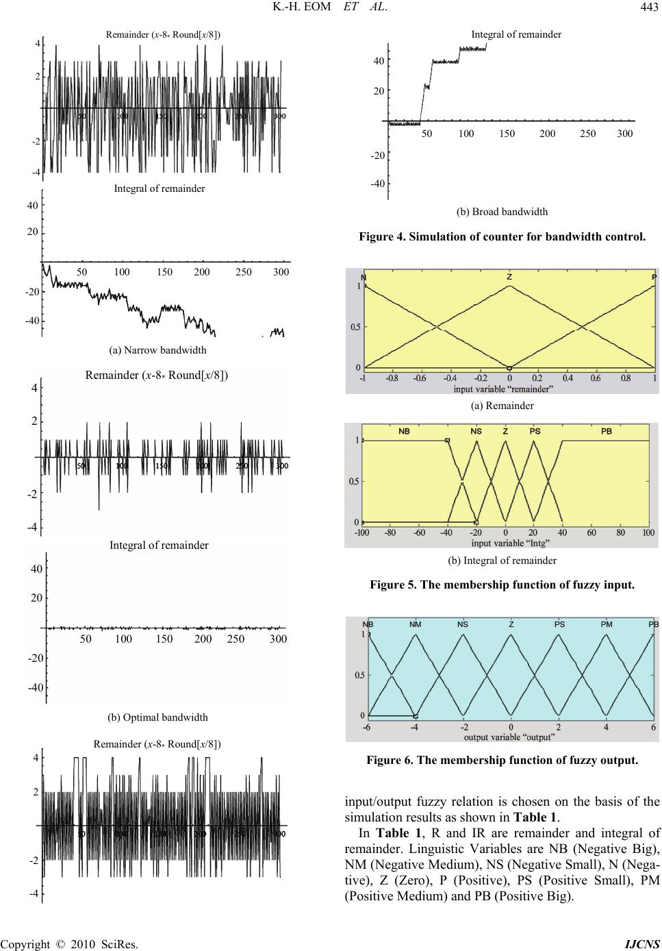 K.-H. EOM ET AL. Copyright © 2010 SciRes. IJCNS 443 Remainder (x-8 * Round[x/8]) 4 2 -2 -4 Integral of remainder 40 20 -20 -40 50 100 150 200 250 300 (a) Narrow bandwidth Remainder (x-8 * Round[x/8]) 4 2 -2 -4 Integral of remainder 40 20 -20 -40 50 100 150 200 250 300 (b) Optimal bandwidth Remainder (x-8 * Round[x/8]) 4 2 -2 -4 Integral of remainder 40 20 -20 -40 50 100 150 200 250 300 (b) Broad bandwidth Figure 4. Simulation of counter for bandwidth control. (a) Remainder (b) Integral of remainder Figure 5. The membership function of fuzzy input. Figure 6. The membership function of fuzzy output. input/output fuzzy relation is chosen on the basis of the simulation results as shown in Table 1. In Table 1, R and IR are remainder and integral of remainder. Linguistic Variables are NB (Negative Big), NM (Negative Medium), NS (Negative Small), N (Nega- tive), Z (Zero), P (Positive), PS (Positive Small), PM (Positive Medium) and PB (Positive Big). 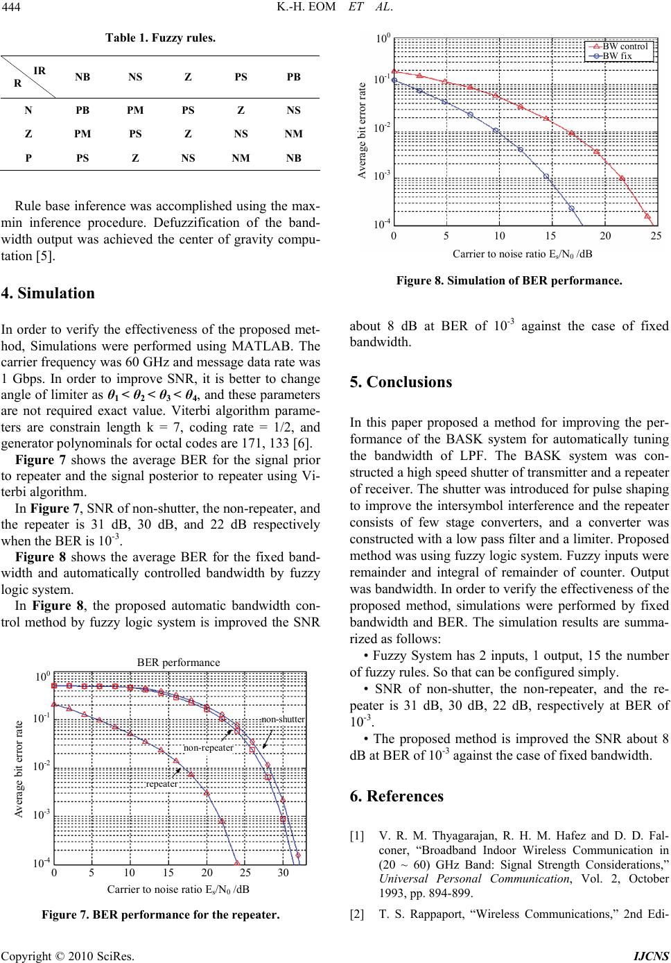 K.-H. EOM ET AL. Copyright © 2010 SciRes. IJCNS 444 Table 1. Fuzzy rules. IR R NB NS Z PS PB N PB PM PS Z NS Z PM PS Z NS NM P PS Z NS NM NB Rule base inference was accomplished using the max- min inference procedure. Defuzzification of the band- width output was achieved the center of gravity compu- tation [5]. 4. Simulation In order to verify the effectiveness of the proposed met- hod, Simulations were performed using MATLAB. The carrier frequency was 60 GHz and message data rate was 1 Gbps. In order to improve SNR, it is better to change angle of limiter as θ1 < θ2 < θ3 < θ4, and these parameters are not required exact value. Viterbi algorithm parame- ters are constrain length k = 7, coding rate = 1/2, and generator polynominals for octal codes are 171, 133 [6]. Figure 7 shows the average BER for the signal prior to repeater and the signal posterior to repeater using Vi- terbi algorithm. In Figure 7, SNR of non-shutter, the non-repeater, and the repeater is 31 dB, 30 dB, and 22 dB respectively when the BER is 10-3. Figure 8 shows the average BER for the fixed band- width and automatically controlled bandwidth by fuzzy logic system. In Figure 8, the proposed automatic bandwidth con- trol method by fuzzy logic system is improved the SNR BER performance Carrier to noise ratio E s /N 0 / dB 0 5 10 15 20 25 30 Average bit error rate repeater non-repeater non-shutter 10 0 10 -1 10 -2 10 -3 10 -4 Figure 7. BER performance for the repeater. Carrier to noise ratio E s /N 0 /dB 0 5 10 15 20 25 Average bit error rate BW control BW fix 10 0 10 -1 10 -2 10 -3 10 -4 Figure 8. Simulation of BER performance. about 8 dB at BER of 10-3 against the case of fixed bandwidth. 5. Conclusions In this paper proposed a method for improving the per- formance of the BASK system for automatically tuning the bandwidth of LPF. The BASK system was con- structed a high speed shutter of transmitter and a repeater of receiver. The shutter was introduced for pulse shaping to improve the intersymbol interference and the repeater consists of few stage converters, and a converter was constructed with a low pass filter and a limiter. Proposed method was using fuzzy logic system. Fuzzy inputs were remainder and integral of remainder of counter. Output was bandwidth. In order to verify the effectiveness of the proposed method, simulations were performed by fixed bandwidth and BER. The simulation results are summa- rized as follows: • Fuzzy System has 2 inputs, 1 output, 15 the number of fuzzy rules. So that can be configured simply. • SNR of non-shutter, the non-repeater, and the re- peater is 31 dB, 30 dB, 22 dB, respectively at BER of 10-3. • The proposed method is improved the SNR about 8 dB at BER of 10-3 against the case of fixed bandwidth. 6. References [1] V. R. M. Thyagarajan, R. H. M. Hafez and D. D. Fal- coner, “Broadband Indoor Wireless Communication in (20 ~ 60) GHz Band: Signal Strength Considerations,” Universal Personal Communication, Vol. 2, October 1993, pp. 894-899. [2] T. S. Rappaport, “Wireless Communications,” 2nd Edi- 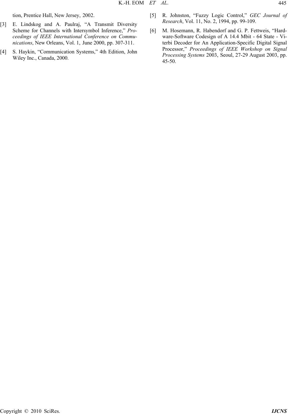 K.-H. EOM ET AL. Copyright © 2010 SciRes. IJCNS 445 tion, Prentice Hall, New Jersey, 2002. [3] E. Lindskog and A. Paulraj, “A Transmit Diversity Scheme for Channels with Intersymbol Inference,” Pro- ceedings of IEEE International Conference on Commu- nications, New Orleans, Vol. 1, June 2000, pp. 307-311. [4] S. Haykin, “Communication Systems,” 4th Edition, John Wiley Inc., Canada, 2000. [5] R. Johnston, “Fuzzy Logic Control,” GEC Journal of Research, Vol. 11, No. 2, 1994, pp. 99-109. [6] M. Hosemann, R. Habendorf and G. P. Fettweis, “Hard- ware-Software Codesign of A 14.4 Mbit - 64 State - Vi- terbi Decoder for An Application-Specific Digital Signal Processor,” Proceedings of IEEE Workshop on Signal Processing Systems 2003, Seoul, 27-29 August 2003, pp. 45-50. |