Paper Menu >>
Journal Menu >>
 Engineering, 2010, 2, 391-396 doi:10.4236/eng.2010.25051 Published Online May 2010 (http://www.SciRP.org/journal/eng) Copyright © 2010 SciRes. ENG 391 Influence of Clad Metal Chemistry on Stress Corrosion Cracking Behaviour of Stainless Steels Claddings in Chloride Solution Edmilson O. Correa1, Reginaldo P. Barbosa2, Augusto J. A. Buschinelli3, Eduardo M. Silva1 1Universidade Federal de Itajuba, Instituto de Engenharia Mecânica, Itajubá, Brazil 2Arcelor Mittal Inox Brazil, Praça 1º de maio, S/N, Centro, Timóteo, Brazil 3Universidade Federal de Santa Catarina, Departamento de Engenharia Mecânica, Florianópolis, Brazil E-mail: ecotoni@unifei.edu.br Received December 1, 2009; revised February 7, 2010; accepted February 12, 2010 Abstract The effect of clad metal composition on stress corrosion cracking (SCC) behavior of three types of SMAW filler metals (E308L-16, E309-16 and E316L-16), used for cladding components subjected to highly corro- sive conditions, was investigated in boiling 43% MgCl2 solution. In order to evaluate the stress corrosion cracking susceptibility of the top layer, constant load tests and metallographic examinations in tested SCC specimens were conducted. The susceptibility to stress corrosion cracking was evaluated in terms of the time-to-fracture. Results showed that the E309-16 clad metal presented the best SCC resistance. This may be attributed to the presence of a discontinuous delta-ferrite network in the austenitic matrix, which acted as a barrier to cracks propagation. Concerning to E308-16 and E316L-16 clad metals, results showed that these presented a similar SCC test performance. Their higher SCC susceptibility may be attributed to the presence of continuous vermicular delta-ferrite in their microstructure. Keywords: Stainless Steels, Cladding, Stress Corrosion Cracking 1. Introduction It is well established that sensitization-induced intergranu- lar stress corrosion cracking of similar austenitic stainless steels weldments occurs predominantly in the heat af- fected zone (HAZ). Because that, traditionally, these steels are joined each other with weld metals containing 5% to ~10% residual delta ferrite in the interdendritic boundaries with the unique objective of reducing the occurrence of hot cracking and microfissuring in the weld metal. In general, little importance is given to the evaluation of the SCC resistance of the weld metal once the HAZ is the region less resistant to SCC and it needs much more attention [1-4]. However, in applications where the austenitic stainless steels are used for cladding components subjected to highly corrosive conditions, the evaluation of the suscep- tibility to SCC of the weld metal turns more relevant [5]. It is worthwhile mentioning that, in cladding applications, reduction of corrosion is achieved by applying a corro- sion resistant surface onto a cheaper and a tougher core material by welding, generally mild carbon steels. According to the literature [4,5], during the early stages of solidification of the major of the austenitic stainless filler metals, the liquid phase initially trans- forms to delta ferrite in a dendritic manner. Simultane- ously, elements with low solubility in the ferrite phase (C, Ni, N, Mn) are rejected to the remaining liquid. As cool- ing continues, the formed delta ferrite undergoes a solid- state transformation to austenite. This solid-state trans- formation occurs by diffusion-controlled migration of the delta ferrite interface and involves the transport of ferrite stabilizers to the ferrite and redistribution of the austenite stabilizers. Previous work has shown that the ferritic phase is more active electrochemically than the austenite phase, resulting in the preferential corrosion of the ferrite on exposure to aggressive environments [6]. The weld metal composition together with the welding thermal cycle experimented by the austenitic stainless steel during the cladding operation have influence on the content of delta ferrite and on the elemental partitioning in the weld metal. Consequently, the SCC resistance of weld metal can differ to that observed in this same mate- rial heat treated by annealing. 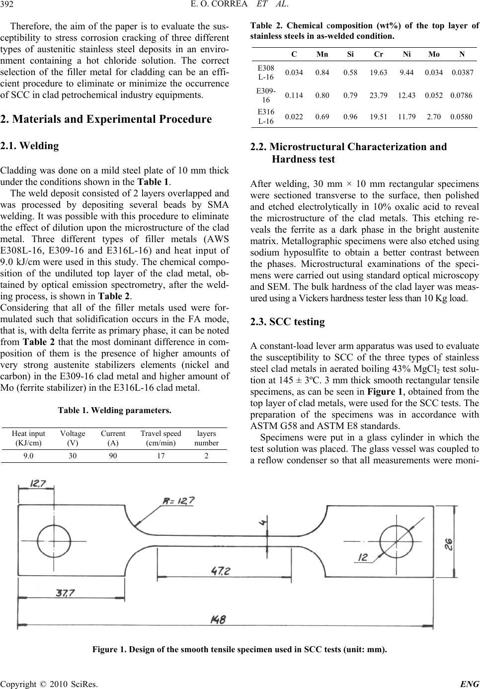 E. O. CORREA ET AL. 392 Therefore, the aim of the paper is to evaluate the sus- ceptibility to stress corrosion cracking of three different types of austenitic stainless steel deposits in an enviro- nment containing a hot chloride solution. The correct selection of the filler metal for cladding can be an effi- cient procedure to eliminate or minimize the occurrence of SCC in clad petrochemical industry equipments. 2. Materials and Experimental Procedure 2.1. Welding Cladding was done on a mild steel plate of 10 mm thick under the conditions shown in the Table 1. The weld deposit consisted of 2 layers overlapped and was processed by depositing several beads by SMA welding. It was possible with this procedure to eliminate the effect of dilution upon the microstructure of the clad metal. Three different types of filler metals (AWS E308L-16, E309-16 and E316L-16) and heat input of 9.0 kJ/cm were used in this study. The chemical compo- sition of the undiluted top layer of the clad metal, ob- tained by optical emission spectrometry, after the weld- ing process, is shown in Table 2. Considering that all of the filler metals used were for- mulated such that solidification occurs in the FA mode, that is, with delta ferrite as primary phase, it can be noted from Table 2 that the most dominant difference in com- position of them is the presence of higher amounts of very strong austenite stabilizers elements (nickel and carbon) in the E309-16 clad metal and higher amount of Mo (ferrite stabilizer) in the E316L-16 clad metal. Table 1. Welding parameters. Heat input (KJ/cm) Voltage (V) Current (A) Travel speed (cm/min) layers number 9.0 30 90 17 2 Table 2. Chemical composition (wt%) of the top layer of stainless steels in as-welded condition. C Mn Si Cr Ni Mo N E308 L-16 0.0340.840.5819.63 9.44 0.0340.0387 E309- 16 0.1140.800.7923.79 12.43 0.0520.0786 E316 L-16 0.0220.690.9619.51 11.79 2.700.0580 2.2. Microstructural Characterization and Hardness test After welding, 30 mm × 10 mm rectangular specimens were sectioned transverse to the surface, then polished and etched electrolytically in 10% oxalic acid to reveal the microstructure of the clad metals. This etching re- veals the ferrite as a dark phase in the bright austenite matrix. Metallographic specimens were also etched using sodium hyposulfite to obtain a better contrast between the phases. Microstructural examinations of the speci- mens were carried out using standard optical microscopy and SEM. The bulk hardness of the clad layer was meas- ured using a Vickers hardness tester less than 10 Kg load. 2.3. SCC testing A constant-load lever arm apparatus was used to evaluate the susceptibility to SCC of the three types of stainless steel clad metals in aerated boiling 43% MgCl2 test solu- tion at 145 ± 3ºC. 3 mm thick smooth rectangular tensile specimens, as can be seen in Figure 1, obtained from the top layer of clad metals, were used for the SCC tests. The preparation of the specimens was in accordance with ASTM G58 and ASTM E8 standards. Specimens were put in a glass cylinder in which the test solution was placed. The glass vessel was coupled to a reflow condenser so that all measurements were moni- Figure 1. Design of the smooth tensile specimen used in SCC tests (unit: mm). Copyright © 2010 SciRes. ENG 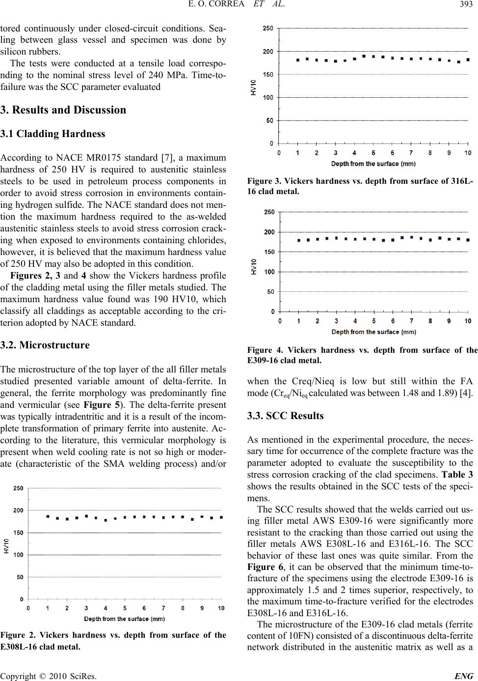 E. O. CORREA ET AL.393 tored continuously under closed-circuit conditions. Sea- ling between glass vessel and specimen was done by silicon rubbers. The tests were conducted at a tensile load correspo- nding to the nominal stress level of 240 MPa. Time-to- failure was the SCC parameter evaluated 3. Results and Discussion 3.1 Cladding Hardness According to NACE MR0175 standard [7], a maximum hardness of 250 HV is required to austenitic stainless steels to be used in petroleum process components in order to avoid stress corrosion in environments contain- ing hydrogen sulfide. The NACE standard does not men- tion the maximum hardness required to the as-welded austenitic stainless steels to avoid stress corrosion crack- ing when exposed to environments containing chlorides, however, it is believed that the maximum hardness value of 250 HV may also be adopted in this condition. Figures 2, 3 and 4 show the Vickers hardness profile of the cladding metal using the filler metals studied. The maximum hardness value found was 190 HV10, which classify all claddings as acceptable according to the cri- terion adopted by NACE standard. 3.2. Microstructure The microstructure of the top layer of the all filler metals studied presented variable amount of delta-ferrite. In general, the ferrite morphology was predominantly fine and vermicular (see Figure 5). The delta-ferrite present was typically intradentritic and it is a result of the incom- plete transformation of primary ferrite into austenite. Ac- cording to the literature, this vermicular morphology is present when weld cooling rate is not so high or moder- ate (characteristic of the SMA welding process) and/or Figure 2. Vickers hardness vs. depth from surface of the E308L-16 clad metal. Figure 3. Vickers hardness vs. depth from surface of 316L- 16 clad metal. Figure 4. Vickers hardness vs. depth from surface of the E309-16 clad metal. when the Creq/Nieq is low but still within the FA mode (Creq/Nieq calculated was between 1.48 and 1.89) [4]. 3.3. SCC Results As mentioned in the experimental procedure, the neces- sary time for occurrence of the complete fracture was the parameter adopted to evaluate the susceptibility to the stress corrosion cracking of the clad specimens. Table 3 shows the results obtained in the SCC tests of the speci- mens. The SCC results showed that the welds carried out us- ing filler metal AWS E309-16 were significantly more resistant to the cracking than those carried out using the filler metals AWS E308L-16 and E316L-16. The SCC behavior of these last ones was quite similar. From the Figure 6, it can be observed that the minimum time-to- fracture of the specimens using the electrode E309-16 is approximately 1.5 and 2 times superior, respectively, to the maximum time-to-fracture verified for the electrodes E308L-16 and E316L-16. The microstructure of the E309-16 clad metals (ferrite content of 10FN) consisted of a discontinuous delta-ferrite network distributed in the austenitic matrix as well as a Copyright © 2010 SciRes. ENG 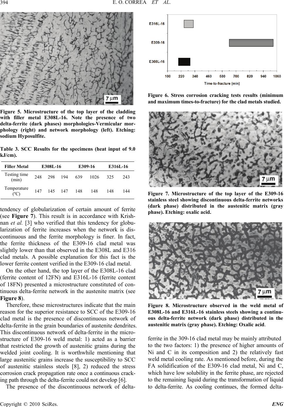 E. O. CORREA ET AL. 394 Figure 5. Microstructure of the top layer of the cladding with filler metal E308L-16. Note the presence of two delta-ferrite (dark phases) morphologies-Vermicular mor- phology (right) and network morphology (left). Etching: sodium Hyposulfite. Table 3. SCC Results for the specimens (heat input of 9.0 kJ/cm). Filler Metal E308L-16 E309-16 E316L-16 Testing time (min) 248 298 194 639 1026 325243 Temperature (ºC) 147 145 147 148 148 148144 tendency of globularization of certain amount of ferrite (see Figure 7). This result is in accordance with Krish- nan et al. [3] who verified that this tendency for globu- larization of ferrite increases when the network is dis- continuous and the ferrite morphology is finer. In fact, the ferrite thickness of the E309-16 clad metal was slightly lower than that observed in the E308L and E316 clad metals. A possible explanation for this fact is the lower ferrite content verified in the E309-16 clad metal. On the other hand, the top layer of the E308L-16 clad (ferrite content of 12FN) and E316L-16 (ferrite content of 18FN) presented a microstructure constituted of con- tinuous delta-ferrite network in the austenite matrix (see Figure 8). Therefore, these microstructures indicate that the main reason for the superior resistance to SCC of the E309-16 clad metal is the presence of discontinuous network of delta-ferrite in the grain boundaries of austenite dendrites. This discontinuous network of delta-ferrite in the micro- structure of E309-16 weld metal: 1) acted as a barrier that restricted the growth of austenitic grains during the welded joint cooling. It is worthwhile mentioning that large austenitic grains increase the susceptibility to SCC of austenitic stainless steels [8], 2) reduced the stress corrosion crack propagation rate once a continuous crack- ing path through the delta-ferrite could not develop [6]. The presence of the discontinuous network of delta- Figure 6. Stress corrosion cracking tests results (minimum and maximum times-to-fracture) for the clad metals studied. Figure 7. Microstructure of the top layer of the E309-16 stainless steel showing discontinuous delta-ferrite networks (dark phase) distributed in the austenitic matrix (gray phase). Etching: oxalic acid. Figure 8. Microstructure observed in the weld metal of E308L-16 and E316L-16 stainless steels showing a continu- ous delta-ferrite network (dark phase) distributed in the austenitic matrix (gray phase). Etching: Oxalic acid. ferrite in the 309-16 clad metal may be mainly attributed to the two factors: 1) the presence of higher amounts of Ni and C in its composition and 2) the relatively fast weld metal cooling rate. As mentioned before, during the FA solidification of the E309-16 clad metal, Ni and C, which have low solubility in the ferrite phase, are rejected to the remaining liquid during the transformation of liquid to delta-ferrite. As cooling continues, the formed delta- Copyright © 2010 SciRes. ENG 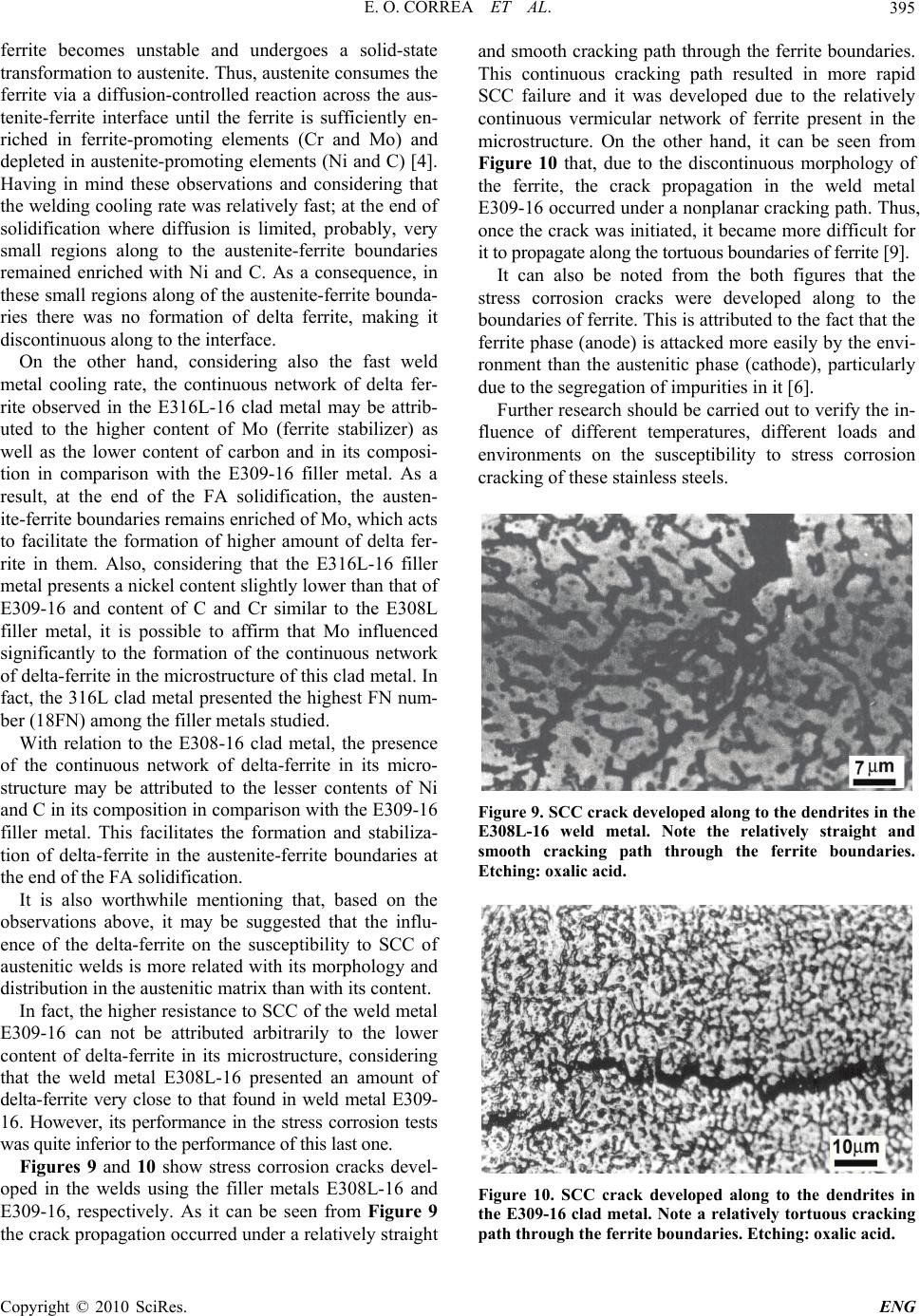 E. O. CORREA ET AL.395 ferrite becomes unstable and undergoes a solid-state transformation to austenite. Thus, austenite consumes the ferrite via a diffusion-controlled reaction across the aus- tenite-ferrite interface until the ferrite is sufficiently en- riched in ferrite-promoting elements (Cr and Mo) and depleted in austenite-promoting elements (Ni and C) [4]. Having in mind these observations and considering that the welding cooling rate was relatively fast; at the end of solidification where diffusion is limited, probably, very small regions along to the austenite-ferrite boundaries remained enriched with Ni and C. As a consequence, in these small regions along of the austenite-ferrite bounda- ries there was no formation of delta ferrite, making it discontinuous along to the interface. On the other hand, considering also the fast weld metal cooling rate, the continuous network of delta fer- rite observed in the E316L-16 clad metal may be attrib- uted to the higher content of Mo (ferrite stabilizer) as well as the lower content of carbon and in its composi- tion in comparison with the E309-16 filler metal. As a result, at the end of the FA solidification, the austen- ite-ferrite boundaries remains enriched of Mo, which acts to facilitate the formation of higher amount of delta fer- rite in them. Also, considering that the E316L-16 filler metal presents a nickel content slightly lower than that of E309-16 and content of C and Cr similar to the E308L filler metal, it is possible to affirm that Mo influenced significantly to the formation of the continuous network of delta-ferrite in the microstructure of this clad metal. In fact, the 316L clad metal presented the highest FN num- ber (18FN) among the filler metals studied. With relation to the E308-16 clad metal, the presence of the continuous network of delta-ferrite in its micro- structure may be attributed to the lesser contents of Ni and C in its composition in comparison with the E309-16 filler metal. This facilitates the formation and stabiliza- tion of delta-ferrite in the austenite-ferrite boundaries at the end of the FA solidification. It is also worthwhile mentioning that, based on the observations above, it may be suggested that the influ- ence of the delta-ferrite on the susceptibility to SCC of austenitic welds is more related with its morphology and distribution in the austenitic matrix than with its content. In fact, the higher resistance to SCC of the weld metal E309-16 can not be attributed arbitrarily to the lower content of delta-ferrite in its microstructure, considering that the weld metal E308L-16 presented an amount of delta-ferrite very close to that found in weld metal E309- 16. However, its performance in the stress corrosion tests was quite inferior to the performance of this last one. Figures 9 and 10 show stress corrosion cracks devel- oped in the welds using the filler metals E308L-16 and E309-16, respectively. As it can be seen from Figure 9 the crack propagation occurred under a relatively straight and smooth cracking path through the ferrite boundaries. This continuous cracking path resulted in more rapid SCC failure and it was developed due to the relatively continuous vermicular network of ferrite present in the microstructure. On the other hand, it can be seen from Figure 10 that, due to the discontinuous morphology of the ferrite, the crack propagation in the weld metal E309-16 occurred under a nonplanar cracking path. Thus, once the crack was initiated, it became more difficult for it to propagate along the tortuous boundaries of ferrite [9]. It can also be noted from the both figures that the stress corrosion cracks were developed along to the boundaries of ferrite. This is attributed to the fact that the ferrite phase (anode) is attacked more easily by the envi- ronment than the austenitic phase (cathode), particularly due to the segregation of impurities in it [6]. Further research should be carried out to verify the in- fluence of different temperatures, different loads and environments on the susceptibility to stress corrosion cracking of these stainless steels. Figure 9. SCC crack developed along to the dendrites in the E308L-16 weld metal. Note the relatively straight and smooth cracking path through the ferrite boundaries. Etching: oxalic acid. Figure 10. SCC crack developed along to the dendrites in the E309-16 clad metal. Note a relatively tortuous cracking path through the ferrite boundaries. Etching: oxalic acid. Copyright © 2010 SciRes. ENG  E. O. CORREA ET AL. Copyright © 2010 SciRes. ENG 396 3. Conclusions 1) The filler metal AWS E309-16 produced a clad layer with higher resistance to SCC than filler metals AWS E308L-16 and E 316L-16 and it is more recommended for cladding equipments subject to SCC. Its microstruc- ture formed by a discontinuous network of delta-ferrite reduced both the austenite grain size during the weld metal solidification and the propagation rate of stress corrosion crack during the SCC tests. 2) The results indicated that the contribution of the delta ferrite in the SCC resistance is much more related with its morphology and distribution than with its con- tent in the austenitic welds. 4. Acknowledgements The authors are grateful to PETROBRAS for supplying the welding consumables and the Brazilians government organizations CNPq and FAPEMIG for the financial support. 5 . References [1] O. M. Alyousif and R. Nishimura, “The Stress Corrosion Cracking Behavior of Austenitic Stainless Steels in Boil- ing Magnesium Chloride Solutions,” Corrosion Science, Vol. 49, No. 7, 2007, pp. 3040-3051. [2] ASM Handbook, “Corrosion,” Metals Park, USA, Vol. 13, 1999. [3] K. N. Krishnan and K. P. Rao, “Effect of Microstructure on Stress Corrosion Cracking Behaviour of Austenitic Stainless Steel Weld Metals,” Materials Science and En- gineering A, Vol. 142, No. 1, 1991, pp. 79-85 [4] J. C. Lippold and D. J. Kotecki, “Welding Metallurgy and Weldability of Stainless Steel,” 5th Edition, John Willey & Sons, Hoboken, 2005. [5] C. D. Lundin, “Dissimilar Metals Welds: Transition Joints Literature Review,” Welding Journal, Vol. 61, No. 2, 1982, pp. 58-63. [6] G. Sui, E. A. Charles and J. Congleton, “The Effect of Delta-Ferrite Content on the Stress Corrosion Cracking of Austenitic Stainless Steels in a Sulphate Solution,” Cor- rosion Science, Vol. 38, No. 5, 1996, pp. 687-703 [7] H. L. Logan, “Stress Corrosion,” 11th Edition, In.: NACE Basic Corrosion Course. Anton deS. Brasunas, Houston, 1990. [8] W. A. Baeslack, W. F. Savage and D. J. Duquette, “Ef- fect of Nitrogen on the Microstructure and Stress Corro- sion Cracking of Stainless Weld Metals,” Welding Jour- nal, Vol. 58, No. 3, 1979, pp. 83-90. [9] V. Y. Gertsman and S. M. Bruemmer, “Study of Grain Boundary Character along Intergranular Stress Corrosion Crack Paths in Austenitic Alloys,” Acta Mater, Vol. 49, No. 9, 2001, pp. 1589-1598. |