 Open Journal of Applied Sciences, 2012, 2, 35-46 doi:10.4236/ojapps.2012.21004 Published Online March 2012 (http://www.SciRP.org/journal/ojapps) Mid-Range W ir eless Power Transfer and Its Application to Body Sensor Networks Fei Zhang1, Jianbo Liu2, Zhihong Mao1, Mingui Sun1 1Department of Neurosurgery, University of Pittsburgh, Pittsburgh, USA 2Department of Electrical and Computer Engineering, Michigan State University, Lansing, USA Email: drsun@pitt.edu Received January 10, 2012; revised February 9, 2012; accepted February 20, 2012 ABSTRACT It has been reported that, through the evanescent near fields, the strongly coupled magnetic resonance is able to achieve an efficient mid-range Wireless Power Transfer (WPT) beyond the characteristic size of the resonator. Recent studies on of the relay effect of the WPT allow more distant and flexible energy transmission. These new developments hold a promise to construct a fully wireless Body Sensor Network (wBSN) using the new mid-range WPT theory. In this paper, a general optimization strategy for a WPT network is presented by analysis and simulation using the coupled mode theory. Based on the results of theoretical and computational study, two types of thin-film resonators are designed and proto- typed for the construction of wBSNs. These resonators and associated electronic components can be integrated into a WPT platform to permit wireless power delivery to multiple wearable sensors and medical implants on the surface and within the human body. Our experiments have demonstrated the feasibility of the WPT approach. Keywords: Body Sensor Network; Strongly Coupled Magnetic Resonance; Wireless Power Transfer; Coupled Mode Theory; Relay Effect 1. Introduction Wireless Body Sensor Networks (wBSNs) have emerged in recent years as a key enabling technology to address a number of significant and persistent challenges in health- care and medical research, including continuous, non- invasive, and inexpensive monitoring of physiological variables. Typically, a wBSN is composed of a number of sensor nodes dedicated to different forms of measure- ments, such as the electrocardiogram (ECG), electro- myogram (EMG), body temperature, glucose, and blood pressure. Each sensor node, which can be either inside (as an implant) or outside (as a wearable device) the human body, is usually composed of an analog readout front-end, a microprocessor, a radio transmitter/receiver, and a power supply. These sensor nodes, wire-connected to a battery, transmit data continuously through a wireless connection to a central node, typically a PDA or a smart cellphone. The central node collects, visualizes and ana- lyzes data and/or wirelessly relays the data or partially processed results to a remote terminal for more advanced off-line processing or evaluation by healthcare profess- sionals. While longer battery capacity, lower power con- sumption, smaller size of the battery and other circuit components, and higher manufacturing volumes have made wBSN data collection more continuous, non-inva- sive, and inexpensive, the progress towards wireless powering has remained to be a significant problem. A great demand exists for developing efficient Wireless Power Transfer (WPT) methods to reduce the dependency on batteries and remove both the network of wire connec- tions around the body and the percutaneous wires pene- trating the human skin. Since the wireless electricity was reported in Science in 2007 [1], this technology has been widely dubbed as “witricity” which joins the first and last a few letters of “wireless electricity” and is the trademark of the Witri- city, Inc. Wireless electricity is based on strongly cou- pled magnetic resonance which has sparked widespread interest in both industrial and academic communities [2-14]. Recently, it has been reported by the same group of the original paper that the approach of powering mul- tiple devices simultaneously can result in a higher overall WPT efficiency compared to the WPT efficiency to each individual device [8]. We analyzed the relay effect [2] which extends the original witricity from the source- device(s) scenario to the source-relay-device scenario, allowing more flexible and distant WPT. In addition to the extended power transmission range, the relay WPT reduces the transmission power at the power source due to the increase in the overall efficiency of energy de- livery. This provides additional human safety from that provided by the wtricity which transmits energy using Copyright © 2012 SciRes. OJAppS  F. ZHANG ET AL. 36 the magnetic field; it is known that the biological tissue responds more passively to the magnetic field than either the electric or electromagnetic field [1]. In this work, we extend our previous experimental re- sults in [9] to address the theoretical and system optimi- zation issues of the witricity in a network fashion. In this network, a group of resonators are involved working in synchrony. We describe the resonator and prototype de- signs specific for wBSN applications, and demonstrate the performance of a proof-of-concept wireless power platform for the construction of wBSNs. The remainder of this paper is organized as follows: Section 2 focuses on the theory of the witricity network. In Section 3 we describe the design and fabrication of our new witricity resonators. What follows demonstrates the results of proposed platform for wBSN in Section 4. Sec- tion 5 discusses and suggests the potential applications of witricity. Finally, conclusions are drawn in Section 6. 2. Theoretical Background A systematic overview about the operational mechanisms of the witricity can be found in [1-3]. Briefly, as shown in Figure 1(a), the basic relay witricity system consists of three resonators: a source, a relay and a device. It also con- sists of a driving loop and an output loop. The source re- sonator is coupled inductively with the driving loop, while the driving loop links to an oscillating power source. Simi- larly, the device coil is coupled inductively with the output loop to supply power to an external load. The resonant eva- nescent strong coupling mechanism between source and device can be mediated by the presence of the relay. The most important property of the witricity is that it operates on the strongly coupled magnetic resonance in the mid-range, which enables the system to achieve a very high frequency selectivity towards the energy receiver [1-3,15]. This can be realized by “tunneling/concentrate- ing” the energy of near-field magnetic fields in a resonant energy avenue from the source resonator to the device resonator via an invisible path over space, with or without being guided by a relay, provided that all resonators have the same frequency. This tunneled energy form will travel between the resonators in an oscillatory fashion, where their coupling time between resonators is required to be much shorter than the loss time [1-3]. Since the resonant wavelength (often in MHz) is usually much larger than the volume of the resonators, the field can circumvent extraneous non-resonant objects in the vicinity of the transmission path, and thus this midrange energy transfer scheme does not require an uninterruptible line-of-sight. In this paper, we further extend the witricity scheme to involving multiple resonators using the coupled mode theory. The general form of the multi-resonator WPT system can be modeled in the following coupled mode matrix form: (see Equation (1)) where i and j is the decimal number ranging from 1 to n (the number of resonators, ); denotes the signal amplitude of the resonator; i 2n i at 2π i is the indi- vidual angular frequencies; ij k is the coupling coeffi- cient between two resonators; and is the individual intrinsic decay rate. i Equation (1) can be rewritten as d d UAKA iWA t (2) where A is the amplitude matrix; K is the coupling ma- trix; W is the frequency matrix; and Γ is the loss matrix. Assuming that V is the modal matrix whose columns are the eigenvectors of K, and that D is the canonical form of K, i.e., D is a diagonal matrix with K’s eigen- values on the main diagonal, we have VVD, or 1 VDV . Using this canonical matrix representa- tion, we can obtain expBiKDiWt (3) Thus, the analytic solution of (2) can be written as 10AVBVAt (4) where 0At is the initial amplitude matrix. Above general solution can work for any number of sources, relays and devices. In order to understand the physical mechanism more easily, we will next focus on a 3 by 3 network as shown in Figure 1(b), where a maxi- mum of 9 identical resonators are involved. For clarity, we use red, yellow and green to represent “source”, “re- lay” and “device” resonators, respectively, in all remain- ing figures when these resonators are studied. We choose resonant frequency fo = 1 MHz and intrinsic loss Γo = 1000 for all resonators, and k = 500,000 between reson- ators 1 and 5. The fact that the coupling, in theory, is inversely proportional to the cube of the separation dis- tances to other elements in the coupling matrix. Substi- tuting these parameters into Equation (4) will enable the alculations of the following WPT scenarios. c 1 11213141 1 1 212 223242 2 2 31323 3343 3 3 1234 d n n n nn nnnn n n iikikikik at at ikiik ikik at at dikik iikik at at t ikikik iki at at (1) Copyright © 2012 SciRes. OJAppS  F. ZHANG ET AL. 37 (a) (b) Figure 1. (a) Basic components of a relay WPT system; (b) 3 by 3 WPT network. 2.1. “Source-Relay(s)-Device” Scheme 2.1.1. Absence of Relay In order to form a complete picture, the first case under analysis is the original witricity scheme as shown in Fig- ure 2(a). In this case, the coupling matrix is [0 1/8; 1/8 0] k, and the initial amplitude matrix will be [1; 0] if we as- sume that all the energy exists in the source side at the starting time. As a key distance-dependent figure-of-merit, the effective coupling parameter represents, intuitively, the ratio of “how fast energy is transferred between the source and device” to “how fast it is dissipated due to in- trinsic losses in these resonators” [1-3]. Since the intrinsic losses are fixed and assumed identical as aforementioned, the speed of energy transfer becomes the evaluation met- rics for the WPT network. In order to gauge the WPT per- formance of the system, we provide a notion of energy exchange time defined as the time required to complete one energy exchange cycle between the source and the device, (the period of the slowest energy exchange frequency), as marked by the arrow in Figure 2, where the energy ex- change time is measured to be 5.1E–5 second. In the gen- eral case (Figures 3 - 14), the energy exchange time indi- cates the period of the energy exchange envelope for the device resonator. Using (1), it can be shown that the energy exchange time is directly related to the coupling coefficient. Apparently, the smaller it is, the higher the efficiency will be. Next, how to minimize the energy exchange time by engineering the coupling matrix is the primary interest to boost the performance of the WPT network. 2.1.2. One Relay The relay effect can greatly enhance the performance of the WPT system with a high efficiency, longer distance and flexible routing. We have analyzed the solutions for one-relay witricity system in [2], where the weaker coup- ling between source and device resonators was ignored to observe the difference between original and relayed cases. Here, we consider all coupling items with a coupling matrix [0 1 1/8; 1 0 1; 1/8 1 0]k. After substituting it into Equation (4), the energy exchanges among resonators are plotted in the Figure 3, where the energy exchange time is reduced to 8.8E–6 second. Compared to Figure 2(b), we can see that the relay for a fixed separation between the source and device resonators accelerates the energy exchange and improves the efficiency, which conforms to our reported experiments in [2] as well. 2.1.3. Two Relays There are three two-relay cases under investigation, shown in Figures 4-6, respectively. Their energy ex- change time is 7.5E–6, 1.3E–5 and 3.2E–6 second, res- pectively. The coupling matrix of Figure 4(a) is [0 1 1/2/ 2 1/8; 1 0 1 1; 1/2/2 1 0 1/2/2; 1/8 1 1/2/2 0] k. Due to the similarity, next coupling matrixes are omitted. Comparing Figure 4 with Figure 3, we can see additional relays for a certain separation will accelerate the energy exchanges when the other relays are fixed. While Figures 4-6 together indicate that different con- figurations of the same number of relays will lead to dif- ferent coupling matrix, and hence different energy trans- Copyright © 2012 SciRes. OJAppS  F. ZHANG ET AL. 38 fer performance. Apparently, the position strategy of Figure 6(a) is the best among the three, which also matches well with our experiments in [2]. The fact that the energy exchange time of Figure 3(a) is smaller than that of Figure 5(a), pointing out that more relays may result in more loose couples if these relays are not well positioned. 2.1.4. Three Relays The three-relay case is investigated as shown in Figure 7(a), and its energy exchange time is 5.1E–6 second. The comparisons between Figures 6 and 7 also de- monstrate that less relay case may combat the more relay case if the relay network is optimized to form a more strongly cou- pling fashion. 0.0 2.0x10 -5 4. 0x10 -5 6. 0x10 -5 8. 0x10 -5 1. 0x10 -4 0. 0 0. 2 0. 4 0. 6 0. 8 1. 0 1. 2 Device Source Normalized Energy Time(Sec) System Energy Exchange Time (a) (b) Figure 2. (a) Resonator position for case 1; (b) Energy exchanges. 0.0 2.0x10 -5 4. 0x10 -5 6. 0x 10 -5 8. 0x10 -5 1. 0x10 -4 0. 0 0. 2 0. 4 0. 6 0. 8 1. 0 1. 2 Device Relay(5) Sour ce Normalized Energy Time(Sec) System (a) (b) Figure 3. (a) Resonator position for case 2; (b) Energy exchanges. 0.0 1. 0x 10 -5 2. 0x10 -5 3. 0x10 -5 4.0x10 -5 5.0x10 -5 0.0 0.2 0.4 0.6 0.8 1.0 1.2 Normalized Energy Time(Sec) Relay(6) De v ic e Rela y ( 5 ) Source System (a) (b) Figure 4. (a) Resonator position for case 3; (b) Energy exchanges. Copyright © 2012 SciRes. OJAppS  F. ZHANG ET AL. 39 0.0 1. 0x 1 0 -5 2.0x1 0 -5 3.0x1 0 -5 4.0x10 -5 5.0x10 -5 0.0 0.2 0.4 0.6 0.8 1.0 1.2 Normalized Energy Time(Sec) Dev ic e Rela y(4 ,6 ) Source Sys t e m (a) (b) Figure 5. (a) Resonator position for case 4; (b) Energy exchanges. 0.0 1. 0x10 -5 2.0 x10 -5 3.0x 10 -5 4.0x 10 -5 5.0x10 -5 0.0 0.2 0.4 0.6 0.8 1.0 1.2 Normalized Energy Time (Sec) Relay2 Device Relay1 Sour c e Sys te m (a) (b) Figure 6. (a) Resonator position for case 5; (b) Energy exchanges. 0.01.0x10 -5 2.0x10 -5 3.0x10 -5 4.0x10 -5 5.0x10 -5 0.0 0.2 0.4 0.6 0.8 1.0 Normalized Energy Time (Sec) Relay(5) De vic e Relay(4,6) Sour c e Sys tem (a) (b) Figure 7. (a) Resonator position for case 6; (b) Energy exchanges. 2.1.5. Seven Relay s The seven-relay case in Figure 8(a) is also investigated, and its energy exchange time is 3.1E–6 second as shown in Figure 8(b). 2.1.6. C omparison s Figure 9 lists all the energy exchange time for cases 1 - 7 for easy comparisons and understanding. It can be ob- served that the resonator network optimization is of great importance for improving WPT system performance. The general solution in Equation (4) can well serve this opti mization purpose. 2.2. “Source-Device(s)” Scheme 2.2.1. On e Device The typical “Source-device” witricity scheme as shown in Copyright © 2012 SciRes. OJAppS  F. ZHANG ET AL. 40 0.0 1.0x10 -5 2.0x10 -5 3.0x10 -5 4.0x10 -5 5.0x10 -5 0.0 0.2 0.4 0.6 0.8 1.0 1.2 Normalized Energy Time(Sec) Relay (7, 8) Relay (4,6) Relay (5) Device Relay (2,3) Sourc e Sys te m (a) (b) Figure 8. (a) Resonator position for case 7; (b) Energy exchanges. 1234567 0.0 1.0x10⁻⁵ 2.0x10⁻⁵ 3.0x10⁻⁵ 4.0x10⁻⁵ 5.0x10⁻⁵ Time (Sec) Case Number Figure 9. Comparisons of energy exchange time for cases 1-7. Figure 10(a) is included here for easy understanding. The energy exchange time is 6.3E–6 second in this case. Compared to Figure 2, the exchange time is eight times less, which agrees well with the fact that the coupling is inversely proportional to the separation distance. 2.2.2. Two Devices The first multiple-device scheme is shown in Figure 11(a), where two device resonators are symmetrically distributed around the source resonator. The energy ex- change time is around 4.2E–6 second. Compared with 6.3E–6 second from Figure 10(b), this means that the configuration in Figure 11(a) boosts the WPT perfor- mance and improves the system efficiency, which mat- ches with the experimental results in [8] that powering multiple devices simultaneously can result in a higher overall efficiency. Our comparison clearly illustrates the physical mechanism behind this efficiency improvement. 2.2.3. Four Devic es Figures 12 and 13 give the results of four device resona- tors with the energy exchange times of 3.06E-6 and 1.09E-6 seconds, respectively. These two similar cases with different energy exchange speeds repeat the early conclusion that the optimization of power network sig- nificantly affects the performance of the whole energy ransfer with the same number of resonators. t 0.05.0x10 -6 1.0x10 -5 1.5x10 -5 2.0x10 -5 2.5x10 -5 0.0 0.2 0.4 0.6 0.8 1.0 1.2 Device Sour ce Normalized Energy Time(Sec) Syst e m (a) (b) Figure 10. (a) Resonator position for case 8; (b) Energy exchanges. Copyright © 2012 SciRes. OJAppS  F. ZHANG ET AL. 41 0.0 5.0x10 -6 1.0x10 -5 1.5x10 -5 2.0x10 -5 2.5x10 -5 0.0 0.2 0.4 0.6 0.8 1.0 1.2 Device (1,9) Source Normalized Energy Time(Sec) Syste m (a) (b) Figure 11. (a) Resonator position for case 9; (b) Energy exchanges. 0.0 5.0x10 -6 1. 0x10 -5 1.5x10 -5 2.0x10 -5 2.5x10 -5 0.0 0.2 0.4 0.6 0.8 1.0 Normalized Energy Time (Sec) Device So urce Sys te m (a) (b) Figure 12. (a) Resonator position for case 10; (b) Energy exchanges. 0.0 5.0x10 -6 1. 0x10 -5 1.5x10 -5 2. 0x10 -5 2. 5x10 -5 0. 0 0. 2 0. 4 0. 6 0. 8 1. 0 Normalized Energy Time (Sec) Device So urc e Sys te m (a) (b) Figure 13. (a) Resonator position for case 11; (b) Energy exchanges. 2.2.4. Eight Devices The WPT case with eight device resonators is shown in Figure 14(a), where the energy exchange time is 7.20E–7 for devices 2, 3, 7, and 8, and 9.22E–7 second for devices 1, 4, 6, and 9, respectively. The series of Figures 10-14 rein- forces the two arguments: 1) the more devices, the higher total efficiency; and 2) the better network optimization, the stronger system coupling, which necessitate the theoretical optimization strategy discussed in this section before wire- less power network is put into real construction. Copyright © 2012 SciRes. OJAppS  F. ZHANG ET AL. 42 0.0 5.0x10 -6 1.0x10 -5 1.5x10 -5 2.0x10 -5 2.5x10 -5 0.0 0.2 0.4 0.6 0.8 1.0 1.2 Normalized Energy Time (Sec) So urc e Device(2,3,7,8) Device(1,4,6,9) Sys te m (a) (b) Figure 14. (a) Resonator position for case 12; (b) Energy exchanges. 3. Resonator Design and Prototype Implementation For the wBSN application, a thin-film resonator is highly desirable. This type of resonator can be imprinted or em- bedded to the exterior or interior cover of the parent de- vice to which the electric power will be transferred with- out taking its interior space. This thin-film design not only utilizes the maximum dimensions of the parent device to capture magnetic flux, but also provides the maximum space for the parent device itself. In addition, it facilitates heat dispersion. 3.1. Cylindrical Resonator 3.1.1. C ylindrical Design Our cylindrical resonator design consists of three layers of films as shown in Figure 15(a): two layers of copper (red) and one layer of insulator (blue). The top and middle panels in Figure 15(a) show, respectively, the top and side views of the resonator. The horizontal narrow copper strips (red) in the middle panel represent a helical induc- tor. The yellow lines represent the spaces between the copper strips. The bottom panel shows the side view from the interior. Several vertical copper strips (red) are affixed to the insulator film (blue). These vertical strips form physical capacitors with the coil conductors in the exterior layer. Clearly, this thin-film design represents a compact LC tank circuit. In our design, energy transfer is primarily provided by the magnetic field, while the electric field is mostly confined within the physical capacitors. This fea- ture effectively prevents the leakage of the electrical field and helps reduce health concerns since the biological tis- sue (and other electrically conductive objects) interacts much more strongly with electric fields than with mag- netic fields. Another motivation of our design is to obtain a compact size. By increasing the capacitance using the strips while keeping the same inductance in the LC tank resonator, the operating frequency of the witricity system can be reduced, which is desirable in many practical ap- plications where the size of the parent device is small. In practical applications, the size and shape of the source resonator have fewer restrictions and can be larger than that of the device resonator. A larger source reson- ator can produce stronger magnetic fields for a longer transmission range. Conversely, the size of the device resonator, though preferred to be as large as possible, is usually limited by the size of the parent device. 3.1.2. Implementation of Cylindrical Design As shown in Figure 15(b), in our experiments, we made a larger source resonator in the form of Figure 15(a). It was a large flexible ring with diameter 350 mm, thickness 0.35 mm, and width 29 mm. The insulator had a dielectric constant of 3.74. The exterior copper tape (width 0.635 cm) formed a 4-turn coil. Eight copper strips with 2.54-cm widths were affixed to the insulator film on the internal side. The resonator was incorporated into the waist belt, and the one-turn driving coil (a loop) linked to the RF power source can was attached on the belt to make the system wearable. Using vector network analyzer (8753ES), we set its resonant frequency to be 7 MHz and Q value was measured to be 51.62. Likewise, based on the design in Figure 15(a), a smaller receiver resonator was made as shown in Fi gure 15(c). The exterior copper strip with 0.635-cm width formed a 6-turn coil, and six copper strips with 2.54-cm widths were af- fixed to the insulator film on the internal side. The radius and height of the cell were about 8.1 cm and 5 cm, respec- tively. Similarly, we also designed much smaller reson- ators for other body parts such as arms. A seven-turn coil was used as the output coil to connect and power the load. We also set its resonant frequency to be 7 MHz and mea- sured its Q value as 56.38. For the purpose of observation, an LED was first used as the load, simulating the load ef- fect of electronics devices and allowing visual examina- tion. This LED was then replaced by a resister from which quantitative measurements was performed. Copyright © 2012 SciRes. OJAppS  F. ZHANG ET AL. 43 (a) (b) (c) Figure 15. Cylindrical thin-film resonator: (a) Structure; (b) Source resonator; (c) Device resonator. 3.1.3. P er formance o f Cy lindric a l Design Figure 16(a) shows an experimental 7 MHz witricity system on a workbench. Wireless energy fully illuminated the low-power LED. When we misaligned the axes of source and device resonators, the power was still be trans- mitted efficiently as shown in Figure 16(b). This pheno- menon differs from that of the conventional magnetic induction methods. In order to evaluate system perfor- mance quantitatively, we replaced the LED with a re- sistor whose resistance approximates the impedance of the output terminals at resonance. Utilizing a diode-based RF detector, we measured the RF energy at the input ter- minals of the driving loop and the energy at the load ter- minals of the output loop. Then the power transfer effi- ciencies with and without misalignment are measured and plotted in Figure 17. It can be seen that, the efficiency without misalignment can reach approximately 80% at a 15-cm separation between the transmitter and receiver. It can also be seen that certain misalignments (e.g. 5 cm) between transmitter and receiver cause only a slight drop in efficiency. This tolerance in misalignment is highly desirable in practical applications since, for example, it allows energy to be transmitted to a moving target or multiple locations as in the case of wBSN. 3.2. Planar Resonator 3.2.1. Pl a nar Design In order to satisfy the requirement of commonly used electronics devices, we believe that the planar structure will be desirable since it will be easily implemented by printing this resonator on the internal or external cover, or embedded in the clothes. As shown in Figures 18(a) and (b), the planar thin-film receiver resonator also includes three layers: the top metal layer (black) formed a planar spiral rectangular coil by attaching the metal strip on an insulated thin film (middle layer, transparent), underneath which there are several separated vertical metal strips (a) (b) Figure 16. Witricity system working at 7 MHz: (a) Align- ment setup; (b) Misalignment setup. 1520 25 30 35 40 45 0.0 0.2 0.4 0.6 0.8 1.0 Power Transfer Efficiency Distance (cm) Center Alignment 5 cm shift 10 cm shift Figure 17. Measured transmission efficiency vs. distances of separation for cylindrical de sign. Copyright © 2012 SciRes. OJAppS  F. ZHANG ET AL. 44 (red). The top and bottom metal strips form the capacitor via the insulated middle layer. Clearly, this thinfilm de- sign represents a compact LC tank circuit. This design is very similar to the source resonator design, and the dif- ference lies in changing the belt shape into a planar struc- ture. 3.2.2. Implementation of Planar Design The constructed device resonator is shown in Figures 18(c) and (d) with length 20.5 cm, width 20 cm and thickness 0.35 mm. The coil inductor consists of 6 turns of copper strips (0.635 cm width) and the bottom layer is formed with 8 vertical copper strips (2.54 cm width). We have measured its Q value as 40 using a vector network analyzer (8753ES). Since the Q value is the important factor in evaluating the energy loss, we may further change the spiral inductor into symmetric [16], step width [17] or patterned floating structures [18,19] in the future as the alternative designs to improve the Q value of the resonator. 3.2.3. Perform ance o f Pla na r Design Using the same measurement method with the cylindrical design, the power transfer efficiency of our planar design is plotted in Figure 19. It can be seen that the efficiency reaches above 80 % at a 20 cm separation of transmitter and receiver. 4. Platform for wBSN Applications In our wBSN design, the large cylindrical resonator can be integrated with a waist belt. A separate device con- taining a battery and electronic circuits is attached to the belt to generate the required RF signal and host electronic circuits. Several smaller cylindrical and planar receiver resonators could be embedded in the clothes or implanted within the body, such as the head, chest, abdomen, arms and/or legs, after being integrated with the implantable devices as described previously. In a separate experiment, we utilized a source resonator and several device resonators to simulate the body sensor network. In order to eliminate the health concerns, we use a maximum 500 mW power as the source. Each of these device resonators is magnetically coupled with an energy pick-up coil which is connected to a low-power LED as a load. Figure 20 shows that the LEDs, located on the hand, the head (Figure 20(a)), the limbs (Figure 20(b)) and the belly (Figure 20(c)), are lit by the energy transmitted from the waist belt transmitter. If each LED is replaced by a rectification and regulation circuit, the power produced can be used to operate a microsensor which is either out- side of the body or implanted inside so that we could by- pass the batteries needed by these devices to operate. Similarly, if the resonant signal is modulated appropri- ately, the wireless system can also perform communica- tion tasks. Clearly, this qualitative experiment shows that it is feasible and convenient to use the witricity as a new tool to construct wBSN systems to perform a wide variety of diagnostic or monitoring functions. 5. Discussions Although, currently, long life lithium ion batteries and ethanol fuel cells have been persuaded as ways to make m (a) (b) (c) (d) Figure 18. Schematic and real picture of planar thin-film device resonator: (a) & (c) Top view; (b) & (d) Bottom view. 20 30 40 50 60 0.0 0.2 0.4 0.6 0.8 1.0 Efficiency Separation distance (cm) (a) (b) Figure 19. (a) The measured setup for planar design; (b) Transmission efficiencies vs. distances of separation. Copyright © 2012 SciRes. OJAppS  F. ZHANG ET AL. 45 (a) (b) (c) Figure 20. Wireless power transfer platforms with three schemes for wBSN. the electrical components more mobile, consumers’ ex- pectations are still far to meet due to the added weight and expensive replacement price of batteries. The discovery of witricity, as a new option, is revolutionizing the wireless industry, and holds great promise to leave batteries as a thing of the past. With a lock-and-key mechanism, the witricity enables energy to be transferred only to the intended target, in which the source and device are both tuned to the same resonant frequency [20]. The fact that strongly coupled regime through interaction functions when the two objects is separated by a large distance and even blocked by an additional object brings people considerable confidence for the exploration of practical applications. Its recent success of preliminary applications to consumer electron- ics such as TV, laptops, electrical cars and cellphones [12,14] and biomedical sensors [9,13] have received con- siderable attention in wireless powering and recharging. In addition, nonradiative fields ensure that little energy is lost or would adversely affect the environment. The relay [2] and resonance enhancement [8] effects of witricity, with the network optimization concept presented in this paper, will further enhance the robustness of building a successful WPT network. 6. Conclusion In the past decade, the veritable feast of electrical devices in modern electric era has been enabled by the techno- logical advances. Numbers of unwanted power cords stimulate people to develop the concomitant powering solution from wired to wireless ways. As a new method of wireless energy transfer, witricity has a high potential in medical applications. In this paper, we investigate the fea- sibility of witricity in providing wireless power to wBSN systems. Theoretical analysis has been presented to fully understand the oscillatory behaviors during in the WPT system operation when multiple resonators are involved. Two types of thin film resonators have been specially de- signed, fabricated and quantitatively measured for the con- struction of wBSN systems. A prototype WPT platform has been built and qualitatively evaluated for the wBSN. Our experimental results have indicated that the witricity technology will provide a powerful solution to power mul- tiple sensors for fully wireless BSN applications. 7. Aknowledgements This work was supported in part by US Army contract No. W81XWH-050C-0047 and National Institutes of Health grant No. U01 HL91736. REFERENCES [1] A. Kurs, A. Karalis, R. Moffatt, J. D. Joannopoulos, P. Fisher and M. Soljacic, “Wireless Power Transfer via Strongly Coupled Magnetic Resonances,” Science, Vol. 317, No. 5834, 2007, pp. 83-86. doi:10.1126/science.1143254 [2] F. Zhang, S. A. Hackworth, W. Fu, C. Li, Z. Mao and M. Sun, “Relay Effect of Wireless Power Transfer Using Strongly Coupled Magnetic Resonances,” IEEE Transac- tions on Magnetics, Vol. 47, No. 5, 2011, pp.1478-1481. doi:10.1109/TMAG.2010.2087010 [3] A. Karalis, J. D. Joannopoulos and M. Soljacic, “Efficient Wireless Non-Radiative Mid-Range Energy Transfer,” Annals of Physics, Vol. 323, No. 1, 2008, pp. 34-48. doi:10.1016/j.aop.2007.04.017 [4] C.-J. Chen, T.-H. Chu, C.-L. Lin and Z.-C. Jou, “A Study of Loosely Coupled Coils for Wireless Power Transfer,” IEEE Transactions on Circuits and Systems, Vol. 57, No. 7, 2010, pp. 536-540. [5] Y. Hori, “Motion Control of Electric Vehicles and Pros- pects of Supercapacitors,” IEEJ Transactions on Electri- cal and Electronic Engineering, Vol. 4, No. 2, 2009, pp. 231-239. doi:10.1002/tee.20401 [6] B. L. Cannon, J. F. Hoburg, D. D. Stancil and S. C. Gold- stein, “Magnetic Resonant Coupling as a Potential Means for Wireless Power Transfer to Multiple Small Receiv- ers,” IEEE Transactions on Power Electronics, Vol. 24, No. 7, 2009, pp. 1819-1826. doi:10.1109/TPEL.2009.2017195 [7] R. E. Hamam, A. Karalis, J. D. Joannopoulos and M. Soljacic, “Efficient Weakly-Radiative Wireless Energy Transfer: An EIT-Like Approach,” Annals of Physics, Vol. 324, No. 8, 2009, pp. 1783-1795. doi:10.1016/j.aop.2009.05.005 [8] A. Kurs, R. Moffatt and M. Soljacic, “Simultaneous Copyright © 2012 SciRes. OJAppS  F. ZHANG ET AL. 46 Mid-Range Power Transfer to Multiple Devices,” Applied Physics Letters, Vol. 96, No. 4, 2010, Article ID: 044102. doi:10.1063/1.3284651 [9] F. Zhang, S. A. Hackworth, X. Liu, C. Li and M. Sun, “Wireless Power Delivery for Wearable Sensors and Im- plants in Body Sensor Networks,” 32nd Annual Interna- tional Conference of the IEEE Engineering in Medicine and Biology Society, Argentina, 31 August September 2010, pp. 692-695. [10] S. Cheon, Y. Kim, S. Kang, M. Lee, J. Lee and T. Zyung, “Circuit-Model-Based Analysis of a Wireless Energy- Transfer System via Coupled Magnetic Resonances,” IEEE Transactions on Industrial Electronics, Vol. 58, No. 7, 2011, pp. 2906-2913. doi:10.1109/TIE.2010.2072893 [11] S. L. Ho, J. Wang, W. Fu and M. Sun, “A Comparative Study between Novel Witricity and Traditional Inductive Magnetic Coupling in Wireless Charging,” IEEE Transac- tions on Magnetics, Vol. 47, No. 5, 2011, pp. 1522- 1525. [12] S. Ho, J. Wang, W. Fu and M. Sun, “A Novel Resonant Inductive Magnetic Coupling Wireless Charger with TiO2 Compound Interlayer,” Journal of Applied Physics, Vol. 109, No. 7, 2011, p. 07E502. [13] A. RamRakhyani, S. Mirabbasi and M. Chiao, “Design and Optimization of Resonance-Based Efficient Wireless Power Delivery Systems for Biomedical Implants,” IEEE Transactions on Biomedical Circuits and Systems, Vol. 5, No. 1, 2011, pp. 48-63. doi:10.1109/TBCAS.2010.2072782 [14] http://www.witricity.com/ [15] H. Haus, “Waves and Fields in Optoelectronics,” Pren- tice-Hall, Englewood, 1984. [16] B. L. Ooi, D. X. Xu and P. S. Kooi, “A Comprehensive Explanation on the High Quality Characteristics of Sym- metrical Octagonal Spiral Inductor,” Proceeding of IEEE RFIC Symposiumi, 28 July 2003, pp. 259-262. [17] H. M. Hsu, “Improving the Quality Factor of a Broadened Spiral Inductor with Arithmetic-Procession Step Width,” Microwave and Optical Technology Letters, Vol. 45, No. 2, 2005, pp. 118-120. doi:10.1002/mop.20741 [18] C. A. Chang, S. P. Tseng, S. S. Jiang and J. A. Yeh, “Characterization of Spiral Inductors with Patterned Float- ing Structures,” IEEE Transactions on Microwave Theory and Techniques, Vol. 52, No. 5, 2004, pp. 1375-1381. doi:10.1109/TMTT.2004.827002 [19] C. P. Yue and S. S. Wong, “On-Chip Spiral Inductors with Patterned Ground Shields for Si-Based RFICs,” IEEE Journal of Solid-State Circuits, Vol. 33, No. 5, 1998, pp. 743-752. doi:10.1109/4.668989 [20] A. P. Sample, D. A. Meyer and J. R. Smith, “Analysis, Experimental Results, and Range Adaptation of Mag- netically Coupled Resonators for Wireless Power Trans- fer,” IEEE Transactions on Industrial Electronics, Vol. 58, No. 2, 2011, pp. 544-554. doi:10.1109/TIE.2010.2046002 Copyright © 2012 SciRes. OJAppS
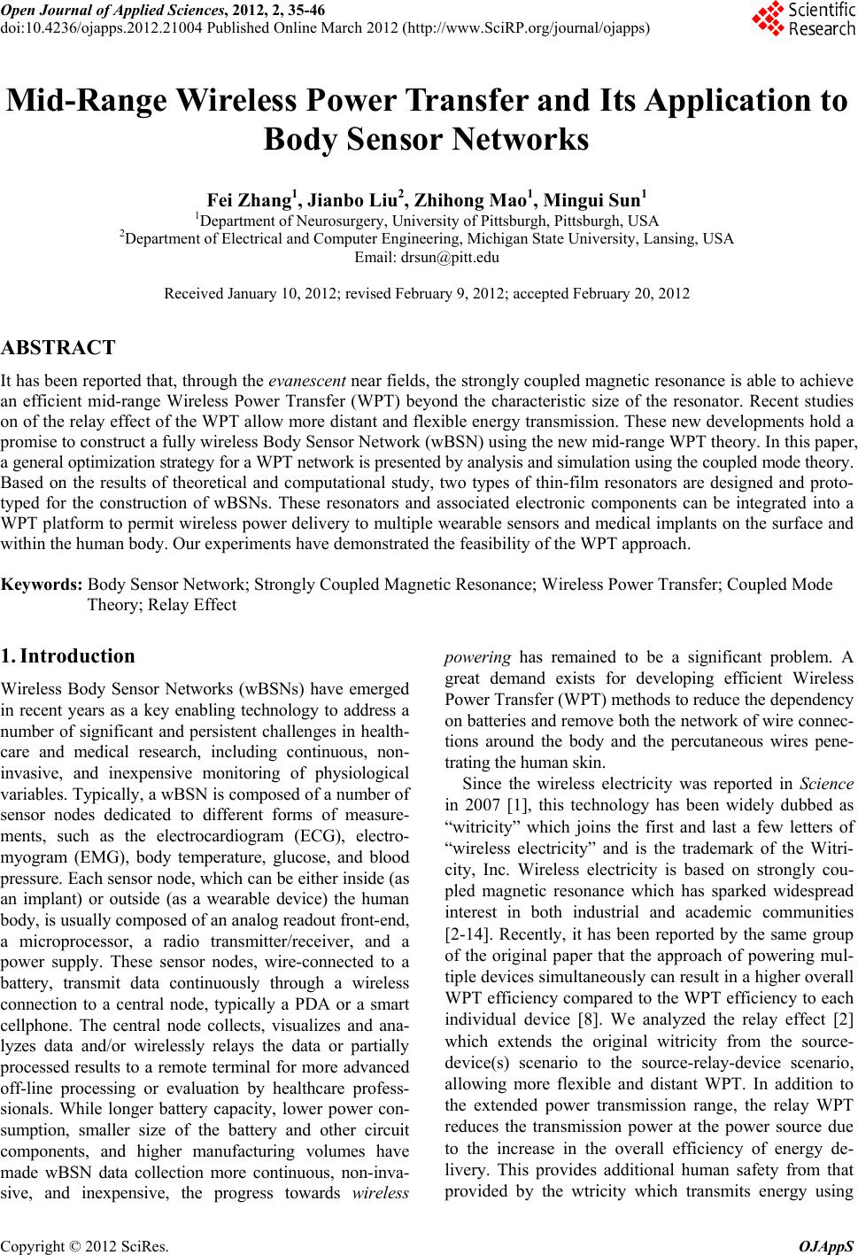
|