Paper Menu >>
Journal Menu >>
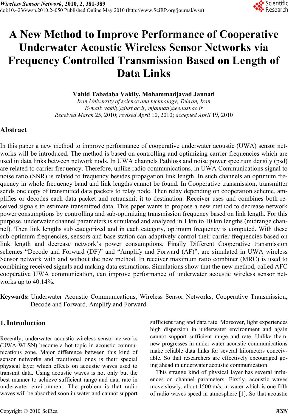 Wireless Sensor Network, 2010, 2, 381-389 doi:10.4236/wsn.2010.24050 Published Online May 2010 (http://www.SciRP.org/journal/wsn) Copyright © 2010 SciRes. WSN A New Method to Improve Performance of Cooperative Underwater Acoustic Wireless Sensor Networks via Frequency Controlled Transmission Based on Length of Data Links Vahid Tabataba Vakily, Mohammadjavad Jannati Iran University of science and technology, Tehran, Iran E-mail: vakily@iust.ac.ir, mjannati@ee.iust.ac.ir Received March 25 , 20 1 0; revised April 10, 2010; accepted April 19, 2010 Abstract In this paper a new method to improve performance of cooperative underwater acoustic (UWA) sensor net- works will be introduced. The method is based on controlling and optimizing carrier frequencies which are used in data links between network nods. In UWA channels Pathloss and noise power spectrum density (psd) are related to carrier frequency. Therefore, unlike radio communications, in UWA Communications signal to noise ratio (SNR) is related to frequency besides propagation link length. In such channels an optimum fre- quency in whole frequency band and link lengths cannot be found. In Cooperative transmission, transmitter sends one copy of transmitted data packets to relay node. Then relay depending on cooperation scheme, am- plifies or decodes each data packet and retransmit it to destination. Receiver uses and combines both re- ceived signals to estimate transmitted data. This paper wants to propose a new method to decrease network power consumptions by controlling and sub-optimizing transmission frequency based on link length. For this purpose, underwater channel parameters is simulated and analyzed in 1 km to 10 km lengths (midrange chan- nel). Then link lengths sub categorized and in each category, optimum frequency is computed. With these sub optimum frequencies, sensors and base station can adaptively control their carrier frequencies based on link length and decrease network’s power consumptions. Finally Different Cooperative transmission schemes “Decode and Forward (DF)” and “Amplify and Forward (AF)”, are simulated in UWA wireless Sensor network with and without the new method. In receiver maximum ratio combiner (MRC) is used to combining received signals and making data estimations. Simulations show that the new method, called AFC cooperative UWA communication, can improve performance of underwater acoustic wireless sensor net- works up to 40.14%. Keywords: Underwater Acoustic Communications, Wireless Sensor Networks, Cooperative Transmission, Decode and Forward, Amplify and Forward 1. Introduction Recently, underwater acoustic wireless sensor networks (UWA-WLSN) become a hot topic in acoustic commu- nications zone. Major difference between this kind of sensor networks and traditional ones is their special physical layer which effects on acoustic waves used to transmit data. Using acoustic waves is not only but the best manner to achieve sufficient range and data rate in underwater environment. The problem is that radio waves will be absorbed soon in water and can not support sufficient rang and data rate. Moreover, light experiences high dispersion in underwater environment and again cannot support sufficient range and rate. Unlike them, new progresses in under water acoustic communications make reliable data links for several kilometers conceiv- able. So that researchers are effectively encouraged go- ing ahead in underwater acoustic communication. This strange kind of physical layer has several influ- ences on channel parameters. Firstly, acoustic waves move slowly, about 1500 m/s, in water which is one fifth of radio waves speed in atmosphere [1]. So that acoustic 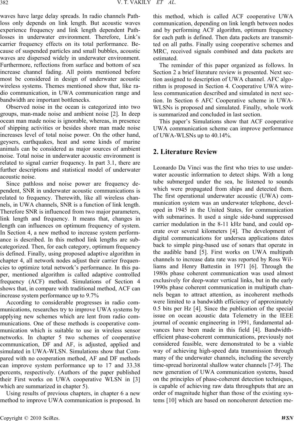 V. T. VAKILY ET AL. 382 waves have large delay spreads. In radio channels Path- loss only depends on link length. But acoustic waves experience frequency and link length dependent Path- losses in underwater environment. Therefore, Link’s carrier frequency effects on its total performance. Be- cause of suspended particles and small bubbles, acoustic waves are dispersed widely in underwater environment. Furthermore, reflections from surface and bottom of sea increase channel fading. All points mentioned before most be considered in design of underwater acoustic wireless systems. Themes mentioned show that, like ra- dio communication, in UWA communication range and bandwidth are important bottlenecks. Observed noise in the ocean is categorized into two groups, man-made noise and ambient noise [2]. In deep ocean man made noise is ignorable, whereas, in presence of shipping activities or besides shore man made noise increases level of total noise power. On the other hand, geysers, earthquakes, heat and some kinds of marine animals can be considered as major sources of ambient noise. Total noise in underwater acoustic environment is related to signal carrier frequency. In part 3.1, there are further descriptions and statistical model of underwater acoustic noise. Since pathloss and noise power are frequency de- pendent, SNR in underwater acoustic communications is related to frequency. Therewith, like all wireless chan- nels, in UWA channels, SNR is a function of link length. Therefore SNR is influenced from two major parameters, link length and frequency. It means that, changes in length can influences on optimum frequency of system. In Section 4, a new method to increase system perform- ance is described. In this method link lengths are sub- categorized. Then, for each category, optimum frequency is defined. Finally, using proposed adaptive algorithm in chapter 4, all network nodes adjust their carrier frequen- cies to optimize total network’s performance. In this pa- per, mentioned algorithm is called adaptive controlled frequency (ACF) method. Simulations of Section 4 shows that, in compare with traditional method, ACF can increase system performance up to 9.7% According to considerable progresses in radio com- munications, researches try to improve UWA systems by applying new schemes which are lent from radio com- munications. One of these methods is cooperative com- munication which is suitable to use in wireless sensor networks. In chapter 5 two schemes of cooperative communication, DF and AF, is adjusted, applied and simulated in UWA-WLSN. Simulations show that Com- pared with no cooperation method, AF and DF methods can improve system performance up to 17 and 33.38 percents, respectively. (Authors of the paper published their First works on UWA cooperative WLSN in [3] which are summarized in chapter 5). Using results of previous chapters, in chapter 6 a new method to improve UWA communication is proposed. In this method, which is called ACF cooperative UWA communication, depending on link length between nodes and by performing ACF algorithm, optimum frequency for each path is defined. Then data packets are transmit- ted on all paths. Finally using cooperative schemes and MRC, received signals combined and data packets are estimated. The reminder of this paper organized as follows. In Section 2 a brief literature review is presented. Next sec- tion assigned to descrip tion of UWA channel. AFC algo- rithm is proposed in Section 4. Cooperative UWA wire- less communication described and simulated in next sec- tion. In Section 6 AFC Cooperative scheme in UWA- WLSNs is proposed and simulated. Finally, whole work is summarized and concluded in last section. This paper’s Simulations show that ACF cooperative UWA communication scheme can improve performance of UWA-WLSNs up to 40.14%. 2. Literature Review Leonardo Da Vinci was the first who tries to use under- water acoustic information to detect ships. With a long tube submerged under the sea, he listened to sounds which were propagated from ships and detected them. The first operational underwater acoustic (UWA) com- munication system was an underwater telephone, devel- oped in 1945 in the United States, for communication with submarines. It used a single side-band suppressed carrier modulation in the 8-11 kHz band, and could op- erate over several kilometers [4]. The development of digital communications for undersea applications dates back to simple ping-based use of sonars that operate in the audible band [5]. First works on UWA multipath channels to increase data rate was reported by Ross W il- liams and Henry Battestin in 1971 [6]. Through the 1980s phase coherent communication was used almost exclusively for deep-water vertical links, but in the early 1990s phase coherent communication in multipath chan- nels began to attract attention, as incoherent methods were limited to a bandwidth efficiency of approximately 0.5 bits per Hz [4]. Since the publication of the special issue on ocean acoustic data Telemetry in the IEEE journal of oceanic engineering in 1991, fundamental ad- vances have been made in this field [4]. Bandwidth- efficient phase-coherent communications, previously not considered feasible, were demonstrated to be a viable way of achieving high-speed data transmission through many of the underwater channels, including the severely time-spread horizontal shallow water chan nels [7-9]. The new generation of UWA communication systems, based on the principles of phase-coherent detection techniques, is capable of achieving raw data throughputs that are an order of magnitude higher than those of the existing sys- tems [10] which ar e based on noncoheren t detection me- Copyright © 2010 SciRes. WSN 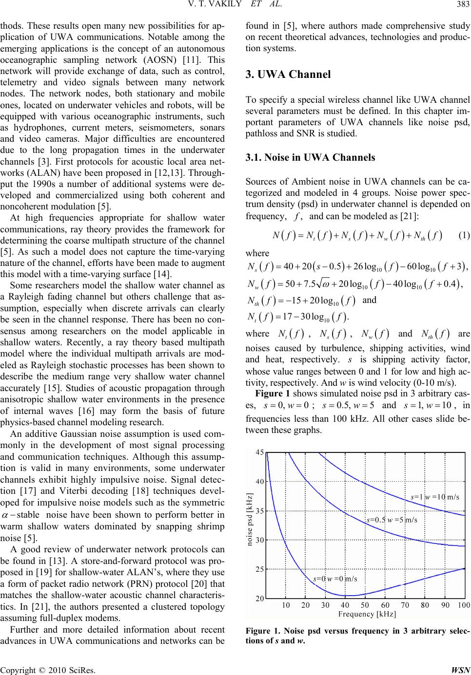 V. T. VAKILY ET AL.383 thods. These results open many new possibilities for ap- plication of UWA communications. Notable among the emerging applications is the concept of an autonomous oceanographic sampling network (AOSN) [11]. This network will provide exchange of data, such as control, telemetry and video signals between many network nodes. The network nodes, both stationary and mobile ones, located on underwater vehicles and robots, will be equipped with various oceanographic instruments, such as hydrophones, current meters, seismometers, sonars and video cameras. Major difficulties are encountered due to the long propagation times in the underwater channels [3]. First protocols for acoustic local area net- works (ALAN) have been proposed in [12,13]. Through- put the 1990s a number of additional systems were de- veloped and commercialized using both coherent and noncoherent modulation [5]. At high frequencies appropriate for shallow water communications, ray theory provides the framework for determining the coarse multipath structure of the channe l [5]. As such a model does not capture the time-varying nature of the channel, efforts have been made to augment this model with a time-varying surface [14]. Some researchers model the shallow water channel as a Rayleigh fading channel but others challenge that as- sumption, especially when discrete arrivals can clearly be seen in the channel response. There has been no con- sensus among researchers on the model applicable in shallow waters. Recently, a ray theory based multipath model where the individual multipath arrivals are mod- eled as Rayleigh stochastic processes has been shown to describe the medium range very shallow water channel accurately [15]. Studies of acoustic propagation through anisotropic shallow water environments in the presence of internal waves [16] may form the basis of future physics-based channel modeling research. An additive Gaussian noise assumption is used com- monly in the development of most signal processing and communication techniques. Although this assump- tion is valid in many environments, some underwater channels exhibit highly impulsive noise. Signal detec- tion [17] and Viterbi decoding [18] techniques devel- oped for impulsive noise models such as the symmetric stable noise have been shown to perform better in warm shallow waters dominated by snapping shrimp noise [5]. A good review of underwater network protocols can be found in [13]. A store-and-forward protocol was pro- posed in [19] for shallow-water ALAN’s, where they use a form of packet radio network (PRN) protocol [20] that matches the shallow-water acoustic channel characteris- tics. In [21], the authors presented a clustered topology assuming full-duplex modems. Further and more detailed information about recent advances in UWA communications and networks can be found in [5], where authors made comprehensive study on recent theoretical advances, technologies and produc- tion systems. 3. UWA Channel To specify a special wireless channel like UWA channel several parameters must be defined. In this chapter im- portant parameters of UWA channels like noise psd, pathloss and SNR is studied. 3.1. Noise in UWA Channels Sources of Ambient noise in UWA channels can be ca- tegorized and modeled in 4 groups. Noise power spec- trum density (psd) in underwater channel is depended on frequency, , f and can be modeled as [21]: tswth NfNf Nf Nf Nf (1) where 10 10 40200.526log60log3 , s Nf sff 10 10 507.520log40log0.4 , w Nff f 10 15 20log th Nf f and 10 17 30log. t Nf f where t Nf, s Nf, and w Nf th Nf are noises caused by turbulence, shipping activities, wind and heat, respectively. s is shipping activity factor, whose value ranges between 0 and 1 for low and high ac- tivity, respectively. And w is wind velocity (0-10 m/s). Figure 1 shows simulated noise psd in 3 arbitrary cas- es, 0, 0sw ; 0.5, 5sw and , in frequencies less than 100 kHz. All other cases slide be- tween these graphs. 1, 10sw Figure 1. Noise psd versus frequency in 3 arbitrary selec- tions of s and w. Copyright © 2010 SciRes. WSN  V. T. VAKILY ET AL. 384 r 3.2. Pathloss and SNR in UWA Channels Signals in UWA Channels experience frequency and link length dependent pathloss which is more complicated than radio channels and can be modeled as 3 10 10log 10Tr (2) where is link length and absorption coefficient, r , is function of frequency. 22 4 2 0.11 44 2.75 100.003 4100 1 ff ff f (3) Figure 2 shows f in frequencies less than 100 kHz. First part of (2) is similar to radio channels and stands for power consumptions of signals which are transmit- ting from source to destination in wireless channels. Second part corresponds to mechanical absorptions of traveling wave’s power in underwater environment which is caused by mechanical nature of acoustic waves and specifies UWA channels. For an arbitrary signal power, by substituting (3) in (2), received power in destination can be computed. There- fore, with aid of (1) we have: ,10log 10log T SNR dfPTN (4) where is signal power, is total noise power in transmission band and is link length. T P N d In Figure 3 relative SNR for several link length be- tween 5 and 100 km simulated and plotted. It is obvious that 3dB bandwidth has inverse ratio with link length. Figure 3 is an endorsement for dependency of opti- mum frequency to link lent. It means that, an optimum frequency cannot be found for whole frequencies and ranges. In next section this problem is studied. Figure 2. Absorption coefficient f in frequencies less than 100 kHz. Figure 3. Relative SNR versus Frequency in 5-100 km. 4. AFC Algorithm As it mentioned before, based on link length between transmitter and receiver nodes, optimum frequency dif- fers. Depending on range of transmission, optimum fre- quency can be com puted fr om 10 3 max,max 10log10log 10 10log iTi dd ii opt iopt SNR dfPd fd Nf (5) In (5), optimum frequency, thii opt f , is the fre- quency which maximizes when ,SNR d fi dd . Therefore i opt f optimizes transmission performance in this range. Figure 4 shows i opt f at different values of link length, . i d Figure 4. i opt f at different values of link length, . i d Copyright © 2010 SciRes. WSN 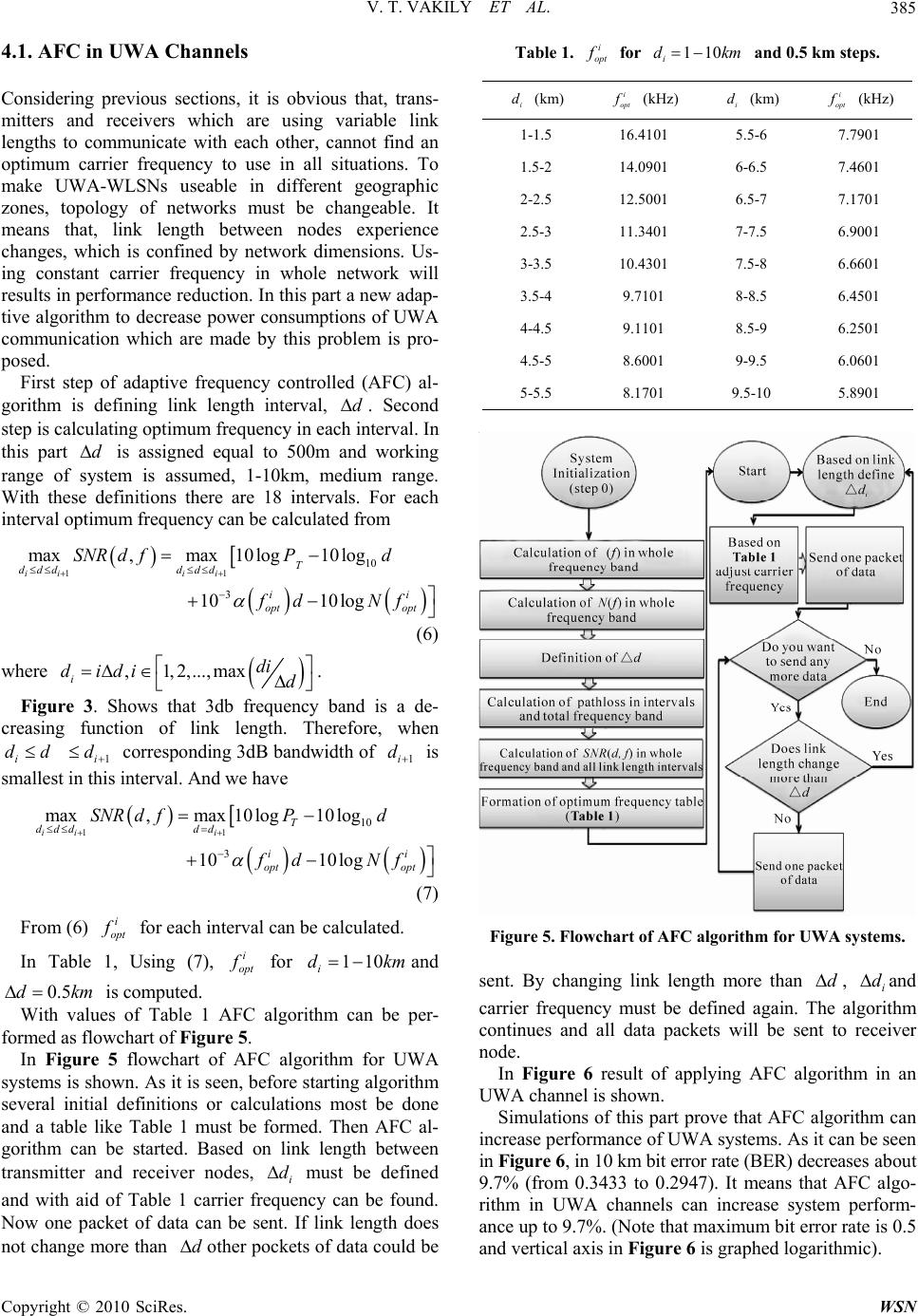 V. T. VAKILY ET AL.385 4.1. AFC in UWA Channels Considering previous sections, it is obvious that, trans- mitters and receivers which are using variable link lengths to communicate with each other, cannot find an optimum carrier frequency to use in all situations. To make UWA-WLSNs useable in different geographic zones, topology of networks must be changeable. It means that, link length between nodes experience changes, which is confined by network dimensions. Us- ing constant carrier frequency in whole network will results in performance redu ction. In this part a new adap- tive algorithm to decrease power consumptions of UWA communication which are made by this problem is pro- posed. First step of adaptive frequency controlled (AFC) al- gorithm is defining link length interval, . Second step is calculating optimum frequency in each interval. In this part is assigned equal to 500m and working range of system is assumed, 1-10km, medium range. With these definitions there are 18 intervals. For each interval optimum frequency can be calculated from d d 11 10 3 max,max 10log10log 10 10log iiii T dddddd ii opt opt SNR dfPd fd Nf (6) where , 1,2,...,max idi didi d . Figure 3. Shows that 3db frequency band is a de- creasing function of link length. Therefore, when corresponding 3dB bandwidth of i dd1i d 1i d is smallest in this interval. And we have 1110 3 max,max 10log10log 1010log iii T ddddd ii opt opt SNR dfPd fd Nf (7) From (6) i opt f for each interval can be calculated. In Table 1, Using (7), i opt f for and is computed. 110 i dk m m0.5dk With values of Table 1 AFC algorithm can be per- formed as flowchart of Figure 5. In Figure 5 flowchart of AFC algorithm for UWA systems is shown. As it is seen, before starting algorithm several initial definitions or calculations most be done and a table like Table 1 must be formed. Then AFC al- gorithm can be started. Based on link length between transmitter and receiver nodes, must be defined and with aid of Table 1 carrier frequency can be found. Now one packet of data can be sent. If link length does not change more than other pockets of data could be i d d Table 1. i opt f for 110 i dkm and 0.5 km steps. i opt f (kHz) i d (km) i opt f (kHz) i d (km) 7.7901 5.5-6 16.4101 1-1.5 7.4601 6-6.5 14.0901 1.5-2 7.1701 6.5-7 12.5001 2-2.5 6.9001 7-7.5 11.3401 2.5-3 6.6601 7.5-8 10.4301 3-3.5 6.4501 8-8.5 9.7101 3.5-4 6.2501 8.5-9 9.1101 4-4.5 6.0601 9-9.5 8.6001 4.5-5 5.8901 9.5-10 8.1701 5-5.5 Figure 5. Flowchart of AFC algorithm for UWA systems. sent. By changing link length more than , di d and carrier frequency must be defined again. The algorithm continues and all data packets will be sent to receiver node. In Figure 6 result of applying AFC algorithm in an UWA channel is shown. Simulations of this part prove that AFC algorithm can increase performance of UWA systems. As it can be seen in Figure 6 , in 10 km bit error rate (BER) decreases abou t 9.7% (from 0.3433 to 0.2947). It means that AFC algo- rithm in UWA channels can increase system perform- ance up to 9.7%. (Note that maximum bit error rate is 0.5 and vertical axis in Figure 6 is graphed logarithmic). Copyright © 2010 SciRes. WSN  V. T. VAKILY ET AL. 386 Figure 6. Results of applying AFC algorithm in an UWA channel in compare with traditional scheme. 5. Cooperative Communication Schemes in UWA Networks Concept of spacial diversity attracts attention of wireless communications researchers and results in continuous and massive quests to make use of it in WLSNs. In a wireless channel several paths can exist between trans- mitter and receiver. If some of these paths are independ- ent and have sufficient performance, channel perform- ance can increase by sending copies of data in these paths and combining them in receiver. Since paths are independent total error probability decreases. Therefore channel and system performance increases. Multiple in- put multiple output (MIMO) systems make use of special diversity by using several antennas in transmitter and receiver. These antennas must be separated enough to make corresponding paths independent. But In many usages of WLSNs it is impossible. Because network nodes maybe smaller than they could support such sepa- rated antennas. To solve this problem idea of cooperative communication is proposed. In cooperative communica- tion systems, transmitter sends one copy of transmitted data packets to relay node. Then relay depending on co- operation scheme, amplifies or decodes each data packet and retransmit it to destination. If relay has proper posi- tion, relay path will be independent from direct path. Receiver uses and combines both received signals to estimate transmitted data [3]. In Figure 7 simplified model of one relay UWA co- operative channel, which will be used in continuation of the paper, is shown. In next section two frequently used cooperative schemes, DF and AF, in WLSNs is defined and applied to an UWA cooperative WLSNs. Figure 7. UWA cooperative channel. 5.1. DF and AF in UWA Cooperative WLSNs Basic idea of DF is that one copy of data which is sent to receiver must be sent to relay too. In relay, this message is decoded, corrected, coded and retransmitted to desti- nation. In destination data which is received from both paths are decoded, corrected and combined to estimate transmitted message. With this approach nether bit rate is achievable [22]. 12 12 21 23 () sup max;,,; df P RIXYXIXX Y (8) It means that relay decodes message perfectly and re- transmits it to destination. In Gaussian channels, if transmitter and relay send their data coherently, above rate will be achievable. In Figure 7 transmitter, relay and receiver nodes are called 1, 2 and 3, respectively. In Gaussian relay chan- nels, channel gain between nodes i and (j,ij , 1,2,3ij ) is called . Received signals in relay and receiver experience additive white Gaussian noise with unit power. Moreover power constraints in trans- mitter and receiver are, ij h 2 1 EX 1 P and 2 2 EX , respectively. By computing (7), for Gaussian chan- nel we have [23]: 2 P 2 21 1 01 22 22 311322313212 max minlog(11), log 12 RhP hPhP hhPP (9) is a real constant and shows correlation between 1 X and 2 X Which are transmitted data from transmitter and relay, respectively. If transmitter 1) and relay 2) cannot transmit coherently, correlation is unusable and 0 . Therefore we have 2 21 1 01 22 31 1322 max minlog1, log 1 Rh hPhP P (10) Copyright © 2010 SciRes. WSN  V. T. VAKILY ET AL.387 In AF scheme, relay node amplifies and retransmits re- ceived signals without decoding it. R elay r ece ives in time . Then by considering power constraints mul- tiplies by 2()yb b 2(y)b . 2 21 1 01 22 31 1322 max minlog1, log 1 Rh hPhP P 1 (11) A Gaussian relay channel which is modeled as coming expressions is considered. 22112 1 33113 22 33223 YihXiZi YihXiZi YihXi Zi (12) where and are received signals from relay and transmitter. If all noise powers are unit and power con- straints in transmitter and receiver are , we have: 1 3 Y2 3 Y P 2 21 1 P hP (13) And AF can achieve bit rate 22 232 21 31 22 21 32 log 11 hhP RPh hPhP (14) If system works in low SNR regime Which means , We will have 0P 2 231 31 log 1ln 2 hP RPh (15) It means that in such situation, relay channel cannot help improving system performance and is unusable. Because in AF scheme both noise and power are ampli- fied and in low SNR AF cannot help data estimation in receiver. In Figure 8 performances of one relay cooperative UWA AF and DF channels is simulated and are com- pared with no cooperation mode. In this figure horizontal axis is distance between transmitter and receiver and vertical axis is bit error rate (BER) which is representa- tive of system performance. Relay position is same as Figure 7 and , the angle between relay path and di- rect path in receiver is . ˆ O15 Figure 8 shows that UWA cooperative schemes can improve performance of UWA-WLSNs. Maximum im- provement is at 7500m where BER decreases from 0.2596 in noncooperation mode to 0.0927 in DF mode and 0.1755 in AF mode which means 33.38% and 17%, respectively. (Note that maximum bit error rate is 0.5 and vertical axis in Figure 8 is graphed logarithmic). Costs of such improvements are relay establishment and cor- responding source usages. Figure 8. Performance of one relay UWA channel with and without cooperation. As it can be seen in Figure 8, if length of direct path decreases performance improvement of cooperative schemes decreases too. When direct path decreases less than 5 km, relay path will be longer than it. Therefore relay path experiences larger Pathloss and cooperative channel tends to weak relay channel. As it mentioned in last part, if relay channel is weak which means experi- ences low SNR, relay channel will not help improving system performance and will be unusable. 6. AFC Cooperative UWA Algorithm In Sections 4 and 5 AFC algorithm and Cooperative schemes in UWA system are described separately. In this section, AFC cooperative UWA algorithm which is a combination of cited methods in Section 4 and 5 is pro- posed. 6.1. AFC Cooperative UWA-WLSNs In AFC cooperative UWA method transmissions be- tween all nodes (transmitters or relays) obey AFC algo- rithm which is shown in Figure 5. It means that for direct path and each part of relay path, carrier frequency must be defined by AFC algorithm and these frequen- cies may differ in different link lengths. Therefore if AFC algorithm is applied in all parts of all paths, sys- tem may use different working frequencies simultane- ously and such networks are called AFC cooperative UWA- WLSNs. In Figure 9 AFC cooperative UWA methods are si- mulated and compared with other cited methods. De- pending on cooperation scheme, AF and DF, new meth- ods are called AF-AFC-UWA and DF-AFC-UWA methods, respectively. Copyright © 2010 SciRes. WSN  V. T. VAKILY ET AL. 388 Figure 9. AFC cooperative UWA schemes compared with AF, DF and traditional schemes in an UWA-WLSN. In simulations of this part, based on proposed model in Figure 7, transmitter power is 90 watts, relay position is 5km away from receiver, angle between direct path and relay path in receiver, , is and direct path differs from 2 km to 10 km. In receiver maximum ratio com- biner (MRC) is used to combine received signals and make data estimations. ˆ O15 In Figure 9, like Figure 8, when length of direct path decreases, performance improvements which are made by cooperative schemes decrease too. In such situations, in spite of cooperative schemes, AFC algorithm plays its role and improves system performance. Simulations of this part show that maximum im- provement is happened in 8km where BER decreases form 0.2801 in traditional scheme to 0.0794 in DF-AFC- UWA scheme which means 40.14%. (Note that maxi- mum bit error rate is 0.5 and vertical axis in Figure 9 is graphed logarithmic). 7. Conclusions and Summaries In This paper a new method to improve performance of cooperative UWA-WLSNs is proposed and evaluated v ia simulations. The method is based on controlling and op- timizing carrier frequencies which are used in data links between network nods. In UWA channels Pathloss and noise psd are related to carrier frequency. Therefore, unlike radio communications, in UWA Communications SNR is related to frequency besides propagation link length. In such channels an optimum frequency in whole frequency band and link lengths cannot be found. To solve this problem AFC algorithm is proposed. In Cooperative transmission, transmitter sends one copy of transmitted data packets to relay node. Then re- lay depending on cooperation scheme, amplifies or de- codes each data packet and retransmit it to destination. Receiver uses and combines both received signals to estimate transmitted data. In this paper, receiver uses MRC to combine received signals and make data estima- tions. To use special diversity of cooperative communi- cation in UWA-WLSNs these methods are applied and simulated. In first section of the paper, UWA communication is introduced. In Section 2 a summarized literature review of UWA communications is offered. In subsequent sec- tion, UWA channel introduced and some of its parame- ters formulated. AFC algorithm for UWA channels is proposed in Section 4. Then in next section Cooperative communication schemes, AF and DF, is presented and applied to UWA-WLSNs. Finally, in Section 6 AFC co- operative UWA algorithm in WLSNs is proposed and evaluated within computer simulations. This algorithm is a combination of cooperative transmission and AFC al- gorithm which is proposed in previous sections. Simulations show that the new method, called AFC cooperative UWA communication, can improve per- formance of underwater acoustic wireless sensor net- works up to 40.14%. 8. Acknowledgments Authors would like to express their sincere thanks to Iran Telecommunication Research Center (ITRC) for its val- uable supports. 9. References [1] M. Stojanovic, “Underwater Acoustic Communication Channels: Propagation Models and Statistical Characteri- zation,” IEEE Communications Magazine, Vol. 47, No. 1, January 2009, pp. 84-89. [2] M. Stojanovic, “Underwater Acoustic Networks: Channel Models and Network Coding Based Lower Bound to Transmission Power for Multicast,” IEEE Journal on Se- lected Areas in Communications, Vol. 26, No. 9, De- cember 2008, pp. 1708-1719. [3] V. T. Vakily and M. J. Jannati, “Performance of Coop- erative Transmission in Underwater Acoustic Sensor Networks,” ICCIA International Conference on Control Instrumentation and Automation, Tehran, 26-27 May 2010. [4] M. Stojanovic, “Underwater Acoustic Communications,” IEEE Electro International, Boston, 5 May 1995. [5] M. Chitre, S. Shahabudeen, L. Freitag and M. Stojanovic, “Recent Advances in Underwater Acoustic Communica- tions & Networking,” IEEE Journal of Oceanic Engi- neering, 2008, pp. 1-10. [6] R. E. Williams and H. F. Battestin, “Coherent Recombi- nation of Acoustic Multipath Signals Propagated in the Deep Ocean,” The Journal of the Acoustical Society of America, Vol. 50, No. 6, 1971, pp. 1433-1442. Copyright © 2010 SciRes. WSN  V. T. VAKILY ET AL. Copyright © 2010 SciRes. WSN 389 [7] M. Stojanovic, J. A. Catipovic and J. G. Proakis, “Phase Coherent Digital Communications for Underwater Acoustic Channels,” IEEE Journal of Oceanic Engineering, Vol. 19, No. 1, January 1994, pp. 100-111. [8] M. Stojanovic, J. A. Catipovic and J. G. Proakis, “Adap- tive Multichannel Combining and Equalization for Un- derwater Acoustic Communications,” The Journal of the Acoustical Society of America, Vol. 94, No. 3, September 1993, pp. 1621-1631. [9] M. Stojanovic, J. A. Catipovic and J. G. Proakis, “Re- duced-Complexity Multichannel Processing of Underwa- ter Acoustic Communication Signals,” The Journal of the Acoustical Society of America, Vol. 98, No. 2, August 1995, pp. 961-972. [10] J. Catipovic. “Performance Limitations in Underwater Acoustic Telemetry,” IEEE Journal of Oceanic Engi- neering, Vol. 15, No. 3, July 1990, pp. 205-216. [11] T. Curtin, J. Bellingham, J. Catipovic and D. Webb, “Autonomous Oceanographic Sampling Networks,” Oce- anography, Vol. 6, No. 3, 1993, pp. 86-94. [12] D. P. Brady and J. A. Catipovic, “Adaptive Multiuser Detection for Underwater Acoustical Channels,” IEEE Journal of Oceanic Engineering, Vol. 19, No. 2, April 1994, pp. 158-165. [13] J. L. Talavage, T. E. Thiel and D. Brady, “An Efficient Store-and-Forward Protocol for a Shallow Water Acous- tic Local Area Network,” Proceedings of the Oceans En- gineering for Today’s Technology and Tomorrow’s Pres- ervation (OCEANS’94), Brest, 13-16 September 1994, pp. I883-I888. [14] C. Bjerrum-Niese, L. Bjorno, M. A. Pinto and B. A. Quellec, “A Simulation Tool for High Data-Rate Acous- tic Communication in a Shallow-Water, Time Varying Channel,” IEEE Journal of Oceanic Engineering, Vol. 21, No. 2, 1996, pp. 143-149. [15] M. Chitre, “A High-Frequency Warm Shallow Water Acoustic Communications Channel Model and Measure- ments,” The Journal of the Acoustical Society of America, Vol. 122, No. 5, 2007, pp. 2580-2586. [16] M. Badiey, B. G. Katsnelson, J. F. Lynch and S. Pere- selkov, “Frequency Dependence and Intensity Fluctua- tions due to Shallow Water Internal Waves,” The Journal of the Acoustical Society of A merica, Vol. 122, No. 2, 2007, pp. 747-760. [17] M. A. Chitre, J. R. Potter and S. H. Ong, “Optimal and Near-Optimal Signal Detection in Snapping Shrimp Dominated Ambient Noise,” IEEE Journal of Oceanic Engineering, Vol. 31, No. 2, 2006, pp. 497-503. [18] M. A. Chitre, J. R. Potter and S. H. Ong, “Viterbi De- coding of Convolutional Codes in Symmetric -stable Noise,” IEEE Transactions on Communications, Vol. 55, No. 12, 2007, pp. 2230-2233. [19] J. Jubin and J. D. Tornow, “The DARPA Packet Radio Network Protocols,” Proceedings of the IEEE, Vol. 75, No. 1, 1987, pp. 21-32. [20] G. G. Xie and J. H. Gibson, “A Network Layer Protocol for UANs to Address Propagation Delay Induced Per- formance Limitations,” MTS/IEEE Oceans’01 Confer- ence, Boston, Vol. 4, 5-8 November 2001, pp. 2087-2094. [21] M. Stojanovic, “On the Relationship between Capacity and Distance in an Underwater Acoustic Communication Channel,” A CM SIGMOB ILE Mobile Comput ing and C om- munications Review, Vol. 11, No. 4, October 2007, pp. 34-43. [22] T. Cover and A. E. Gamal, “Capacity Theorems for the Relay Channel,” IEEE Transactions on Information Theory, Vol. 25, No. 5, 1979, pp. 572-584. [23] A. Host-Madsen and J. Zhang, “Capacity Bounds and Power Allocation for the Wireless Relay Channel,” IEEE Transactions on Information Theory, Vol. 51, No. 6, 2005, pp. 2020-2040. |