Open Journal of Fluid Dynamics
Vol.2 No.4A(2012), Article ID:26359,8 pages DOI:10.4236/ojfd.2012.24A036
Spray Atomization and Structure of Supersonic Liquid Jet with Various Viscosities of Non-Newtonian Fluids
1School of Aerospace & Mechanical Engineering, Korea Aerospace University, Goyang, South Korea
2School of Mechanical Engineering, Andong National University, Andong, South Korea
Email: jykoo@kau.ac.kr
Received September 21, 2012; revised November 3, 2012; accepted November 12, 2012
Keywords: Two-Stage Light Gas Gun; Projectile Impact; Non-Newtonian Fluid; Supersonic Liquid Jet; Shock Wave; SMD
ABSTRACT
These experimental investigations are designed to study shock wave characteristics and spray structure. Supersonic liquid jets injected into ambient fields are empirically studied using projectile impacts in a two-stage light gas gun. This study looks primarily at the design of the nozzle assembly, the tip velocity of the high speed jet, the structure of the spray jet and the shock wave generation process. The supersonic liquid jets were visualized using an ultra high-speed camera and the schlieren system for visualization to quantitatively analyze the shock wave angle. The experimental results with straight cone nozzle types and various non-Newtonian fluid viscosities are presented in this paper. The effects of nozzle geometry on the jet behavior are described. The characteristics of the shock wave generation and spray jet structure were found to be significantly related to the nozzle geometry. The expansion gases accelerated the projectile, which had a mass of 6 grams, from 250 m/s. As a result, it was found that the maximum jet velocity appeared in the liquid jet with high viscosity properties. Supersonic liquid jets, which occurred at the leading edge the shock waves and the compression waves in front of the jets, were observed. Also, the shock waves significantly affected the atomization process for each spray droplet.
1. Introduction
Supersonic liquid jets have been studied in various engineering fields such as material cutting, diesel injection and aerospace rocket nose design, to obtain the supersonic liquid jet break-up and shock wave structure mechanisms [1-3]. In the case of diesel injection, nowadays, operating pressures may exceed 200 MPa, so injection velocities can reach supersonic speeds [4]. A high injection velocity in the combustion field can reduce black smoke and NOx due to good atomization characteristics [5].
Generally, a supersonic liquid jet can be generated with the impact of a high speed projectile made of bronze and stainless steel. At the moment of impact, liquid shock waves are generated in the liquid storage section. Complex interactions of reflection and diffraction should appear inside the nozzle. When the liquid jet is injected into an outer field, supersonic liquid jets penetrate further away from the nozzle exit, and detached shock waves appear in front of the liquid jet. These shock waves are dependent on the injection velocity of the supersonic liquid jets. Also, supersonic liquid jets undergo an aerodynamic drag force that increases atomization performance.
For the investigation of the supersonic liquid jet, many studies related with spray and shock wave structures have been conducted by many researchers [6,7]. Field and Lesser [8] explained the mechanism of the emergence of a high-speed liquid jet from a nozzle orifice at the final stage. They showed that the liquid in the orifice was compressed and the density increased about 1.20 times more than the initial density. At the nozzle exit, the compressed liquid was injected into ambient fields, and a reflected compression wave appeared near the liquid jet, which affected the liquid to air mixing as well as the droplet size. Hiroyasu [9] carried out a fundamental study on spray behavior with focus given to breakup length, spray angle, spray tip penetration and droplet size distributions. He derived a correlated equation of breakup length, which he adapted to fully developed spray jets. He then presented an empirical equation of droplet mean diameter and spray angle and tip penetration. Nakahira [10] configured a high pressure injection apparatus with a compression pressure of 2 MPa and showed that the leading edge bow shock wave would affect the liquid jet breakup. Pianthong [11] re-stressed the supersonic liquid jet structure and assessed the potential ability for autoignition using hydrocarbon fuels with cetane numbers from 50 - 100. Non-Newtonian supersonic liquid jets were investigated by Shi et al. [12]. They compared a water jet and PAA jet in terms of the instability phenomenon. A helical supersonic liquid jet structure emerged with the water jet. However, as the polymer weight density increased to 1.0%, the helical shape disappeared. Thus, in general the overall spray characteristics have been studied. However, penetration and droplet sizes of supersonic non-Newtonian liquid jets have not been fully investigated or clarified as of yet. The purpose of this study is to examine the specific spray characteristics of spray penetration, velocity and droplet size distribution with a non-Newtonian liquid jet.
2. Experimental Procedure
2.1. Two-Stage Light Gas Gun
In this study, a supersonic liquid jet was generated by using the Bowden-Brunton method [13]. This method uses a high speed projectile to accelerate the storage of liquid through a straight cone nozzle. On impact, the momentum of the projectile transfers to the liquid storage, and a supersonic liquid jet forms as it is injected into the ambient air. The high speed projectile required in this technique was launched with a two-stage light gas gun, shown in Figure 1. The gun’s high pressure tube is 68 mm in diameter and 400 mm long. The pump tube is 35 mm in diameter and 800 mm long. The launch tube has a diameter of 25 mm and a length of 380 mm. The high pressure tube is pressurized with 120 bars, and burst diaphragms are placed between the high pressure tube and pump tube. The pump tube accelerates a piston to generate adiabatic compression gas between the pump tube and launch tube. When the gas pressure has risen to the critical pressure of the OHP films, the diaphragm ruptures and the projectile is injected into the launch tube. The piston is comprised of an outer layer of poly-carbonate (PC) assembled insert with a diameter of 30 mm. The projectile is made of bronze with a weight of 6 grams, a diameter of 5 mm and a length of 16 mm. Expansion gases accelerate a projectile from 250 m/s at the exit of the launch tube. The projectile is launched through the pressure relief section, which can diminish the blast wave in front of the projectile.
2.2. Nozzle Assembly
The dimensions of the straight cone nozzle used are detailed in Figure 2 and Table 1. Figure 3" target="_self"> Figure 3 shows a diagram of a straight cone nozzle. The geometry mainly includes two parts: the cavity and the conical shape. The cavity is directly connected to the exit of the pressure relief section, and some liquid is being retained in the nozzle due to the diaphragm at the front of the nozzle. The pressure relief section described previously is used instead of relying on projectile free flight before the impact. After a strong impact, the transiently high momentum of the projectile should transfer to the rear end of the liquid. Then, impact pressure is expected to be generated
Figure 1. Schematics of a two-stage light gas gun used to produce supersonic liquid jets.
Figure 2. Projectile impact driven method.
Figure 3. Nozzle configuration and dimensions.
Table 1. Nozzle geometries.
in the nozzle cavity. This will propel the liquid through the nozzle orifice as a jet with very high speed.
2.3. Spray Visualization Setup
In this study, the supersonic liquid jet is visualized using ultra high-speed camera with a schlieren optical system to describe its dynamic characteristics. The dynamic jet formation and projectile motions are quantitatively measured with sequential observations. The schematic arrangement of the schlieren optical system is shown in Figure 4. The light source was a P7-LED lamp, its generated light passing through a convex lens to focus into a center pin-hole. Two parabolic mirrors and two plane mirrors were used for collimating the source light beam passing the test section area. The ultra high-speed camera was a Photron FASTCAM-APX RS 250 KC model with a frame rate of up to 50,000 fps, an exposure time of 1 μs, and a total number of images of 70. In this experiment, an image resolution of 384 × 96 pixels was used, this being able to capture the jet velocity and penetration up to 2000 m/s and 65 mm.
3. Results and Discussion
3.1. Effect of Various Non-Newtonian Fluid Viscosities
Five non-Newtonian fluid types were investigated in this study. Figure 5 illustrates non-Newtonian fluids with rheological characteristics related to shear rate. When the weight percentage of Polyquater was increased, the viscosities of non-Newtonian fluids increased with the various shear rates. Declined curves show the shearshinning process, which was governed by the molecular interaction in the non-Newtonian fluids. Also, using the power law methods, the consistency index and power law index are shown in Table 2. To measure viscosity with a variation of shear rates, a cone and plate ARES rheometer is used. A pulsed supersonic liquid jet may exceed a shear rate of about 10,000 (1/s) in the nozzle. At the high pressure pulsed injection condition, the non-Newtonian liquid showed a liquefaction phenomenon and the viscosities changed with constant values. The power law model, which is used to describe the shear-thinning phenomenon, was formulated by Ostwald and Waele [14], and the power law equation is given in Equation (1). The power law relation is primarily an exponential relation between the viscosity and shear rate of non-Newtonian fluids.
 (1)
(1)
Many non-Newtonian fluids exhibit significant shearthinning and extensional viscosity characteristics that are governed by break-up and atomization mechanisms, but the physics of this phenomenon are unknown, and those characteristics are not matched to the atomization process by forming stream-wise ligaments, leading to larger mean drop diameters [15]. The rheological properties of gelled propellants strongly influence the orifice inlet flow, spray structure and droplet mean diameter. The viscosity of non-Newtonian fluids, which show viscosities many times higher than that of pure water, is explained with the power law model. A generalized Reynolds number, the equation which is expressed in Equation (2), was formulated by Metzer and Reed [16]. When using the power law, the formula with the generalized Reynolds number is derived by considering the Darcy friction factor. Also, consistency and the power law index are needed to use Regen.
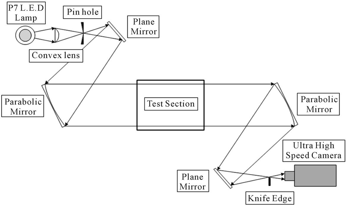
Figure 4. Arrangement of schlieren optical system.
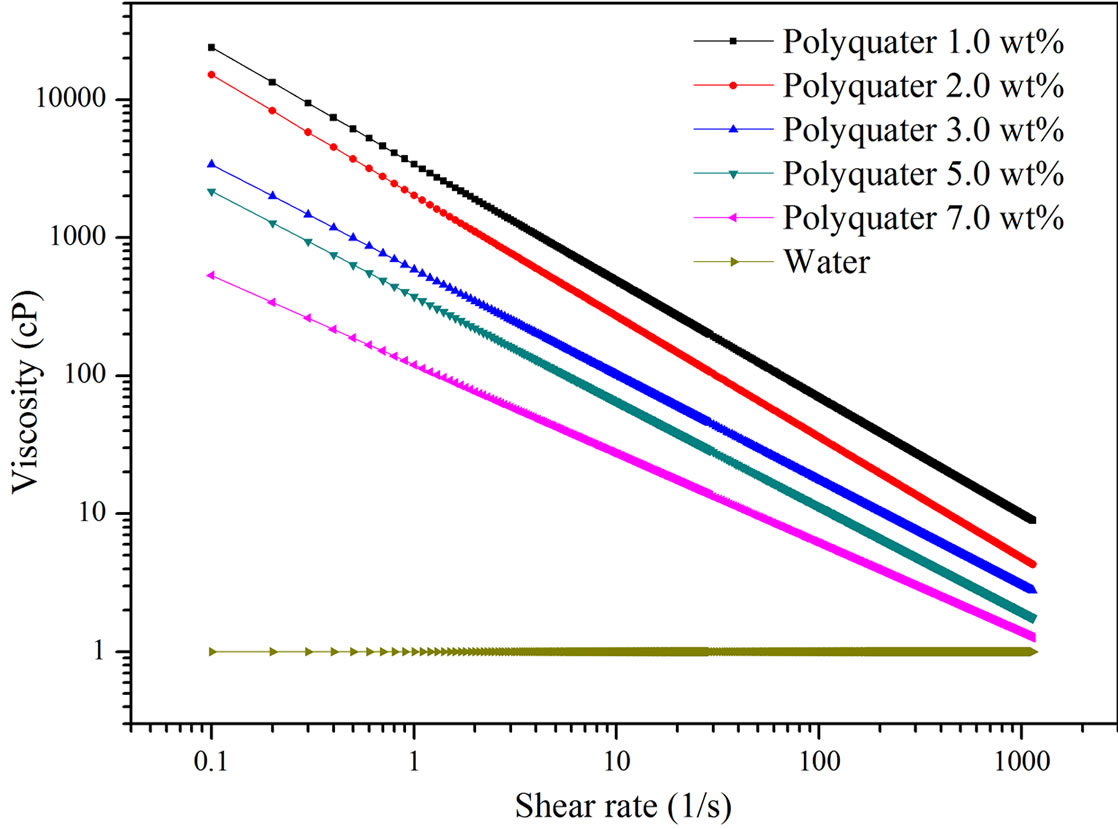
Figure 5. Non-Newtonian fluids of rheological characteristics related to shear rate.
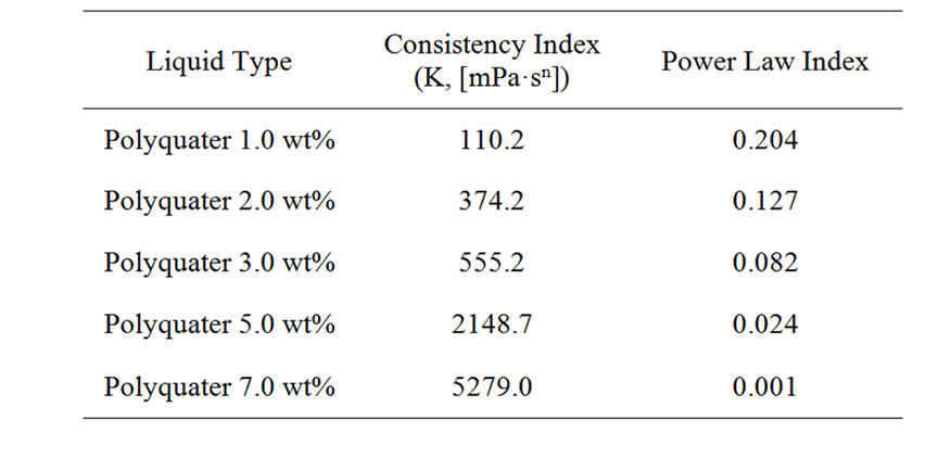
Table 2. Power law data of polyquater gel (20˚C).
 (2)
(2)
3.2. Visualization of Supersonic Liquid Jets
Such a sequential recording is very useful for observing the jet formation. Only eight images are presented where the image width is always 65 mm. In the visualization, 70 frames can be continuously recorded using the ultra high-speed video camera. Therefore, it is possible to visualize the jetting process from its emergence from the nozzle orifice until it passes from the test scene. Figure 6 shows schlieren photographs of the supersonic water jet and polyquater gel jet. These images show clearer signs of the multiple jet pulses compared to the jet from nozzle the L/d = 12. The phenomena of multiple jet pulses and their associated shock wave can be clearly seen. The shock wave at the jet head is bow and oblique in all observations. Figure 6(a) shows the life cycle of a typical
 (a)
(a) (b)
(b) (c)
(c) (d)
(d) (e)
(e) (f)
(f)
Figure 6. Images showing the injection process of supersonic liquid jets from various non-Newtonian fluid viscosities. (a) Water; (b) Polyquarter 1.0 wt%, (c) Polyquarter 2.0 wt%; (d) Polyquarter 3.0 wt%; (e) Polyquarter 5.0 wt%; (f) Polyquarter 7.0 wt%.
water jet traveling at a maximum velocity of 880 m/s, from the initial impingement into quiescent air to the disintegration of the core jet into an atomization droplet.
The initial stage shows that the formation of the bow or detached shock wave is almost instantaneous. At a later stage, 40 - 60 μs, the core jet is surrounded by fine particles of atomized water. Surrounding the body of the jet at 80 μs, a second shock wave is clearly observable. Figures 6(b) and (c) show the motion of the polyquater 1.0 wt% and 2.0 wt%. The maximum jet velocity in polyquater 1.0 wt% and 2.0 wt% are estimated to be 916 m/s and 945 m/s respectively. In the case of polyquater 1.0 wt%, defective jets with unusual shock shapes are presented at 120 μs. This is because the two jet tips may occur due to a defect of the nozzle, which makes the jet head split into two tips [11]. Moreover, a change in the shock wave angle structure can be observed, as shown in Figure 6(c) at 140 μs. Because of the decreasing aerodynamic drag, the jet core, which has a very thin shape, can be more accelerated at a high velocity and fluid viscosity. Figures 6(d) and (e) show the images of the polyquater 3.0 wt% and 5.0 wt%. The angle of the shock wave was changed by the penetrating of the liquid core at the time of 80 μs, as seen in Figure 6(c) at 140 μs. In addition, the shape of the droplet formation around the liquid core can also be observed. A maximum velocity of 1040 m/s and 1050 m/s, respectively, is obtained. Figure 6(f) shows the images of the polyquater 7.0 wt%. It is seen to be narrow and long. The jet tip velocity is extensive, more than 1070 m/s at 100 μs. The attached shock wave is clean and smooth in its development. This may be because the value of the consistency index and surface tension are very high.
3.3. Characteristics of Supersonic Liquid Jets
Figure 7 shows the injection Reynolds number curve with various polyquater powder weight percentages. At the polyquater 1.0 wt%, the maximum value of the injection Reynolds number is observed to be 7.5 × 10⁶. For polyquater 7.0 wt%, the maximum value of the injection Reynolds number is shown to be 3.2 × 10⁶. The reason for the difference between the two cases is explained by recognizing that polyquater 1.0 wt% is composed of weak molecular recoil forces. During the injection process with high pressure, polyquater 1.0 wt% was prone to break-up due to the fast break-up of intermolecular forces. However, polyquater 7.0 wt% was not prone to break-up the due to highly connected molecular forces during the injection process, which enabled the injection Reynolds number to rapidly increase. These molecular forces resist the aerodynamic drag forces at the nozzle exit. The plot showing the effects of various non-Newtonian fluids viscosities on orifice diameter over penetration distance (PD/d) is shown in Figure 8. The test commenced using a nozzle with a 0.5 mm orifice diameter in every case. This had an effect on the PD/d in terms of the water jet being shorter than that of the non-Newtonian fluid jets. This phenomenon is due to the fact that a nonNewtonian fluid has a greater viscosity than water. Moreover, the polyquater 7.0 wt% jet is the slimmest and most elongated, being over 311 at 160 μs. These results show that the high viscosity of the liquid increases the spray penetration distance. Droplet size distributions, which offer information regarding the of cumulative droplet sizes and provide some insight into the basic dispersed droplet phenomenon, of atomized liquid jets with
Figure 7. Effect of various non-Newtonian fluid viscosities on injection Reynolds numbers.
various gelling agents are shown in Figure 9. Due to high viscosity characteristics, polyquater 7.0 wt% shows the SMD value of 137.50 μm. However, by comparing non-Newtonian Fluids, a droplet of water has a small SMD value of 66.53 μm. From the size distributions in Figure 9, polyquater 7.0 wt% has a greater number of large sized droplet distributions than other fluids.
4. Conclusion
Supersonic liquid jets have many advantages and can be applied to material cutting, diesel injection, aerospace rocket nose design and ram jet combustors. This experiment was conducted to study the shock wave characteristics and spray structure through a comparison of nonNewtonian fluids. A supersonic liquid jet injected into an ambient field was empirically studied using a projectile impact in a two-stage light gas gun. The main factor determining the supersonic speed of liquid jets is the impact was of a projectile with an impulse force. At the moment of impact, liquid shock waves were generated in the liquid storage section, and detached shock waves appeared in front of the liquid jet. Supersonic liquid jets which
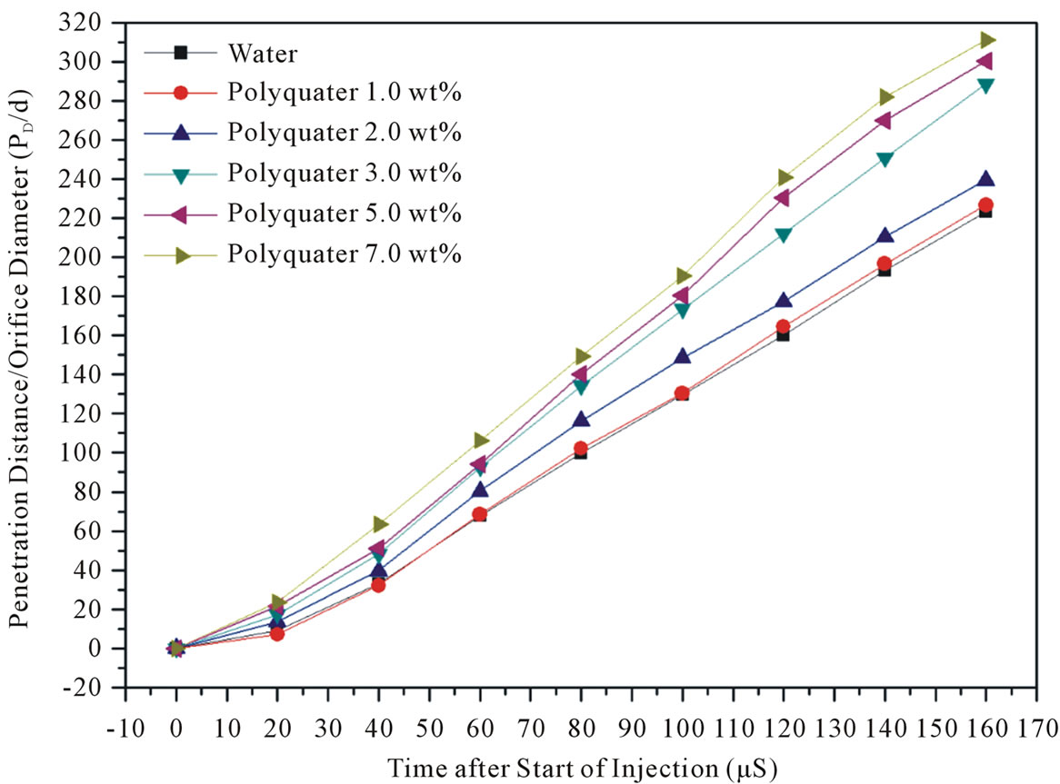
Figure 8. Effect of various non-Newtonian fluid viscosities on orifice diameter over penetration distance (PD/d).
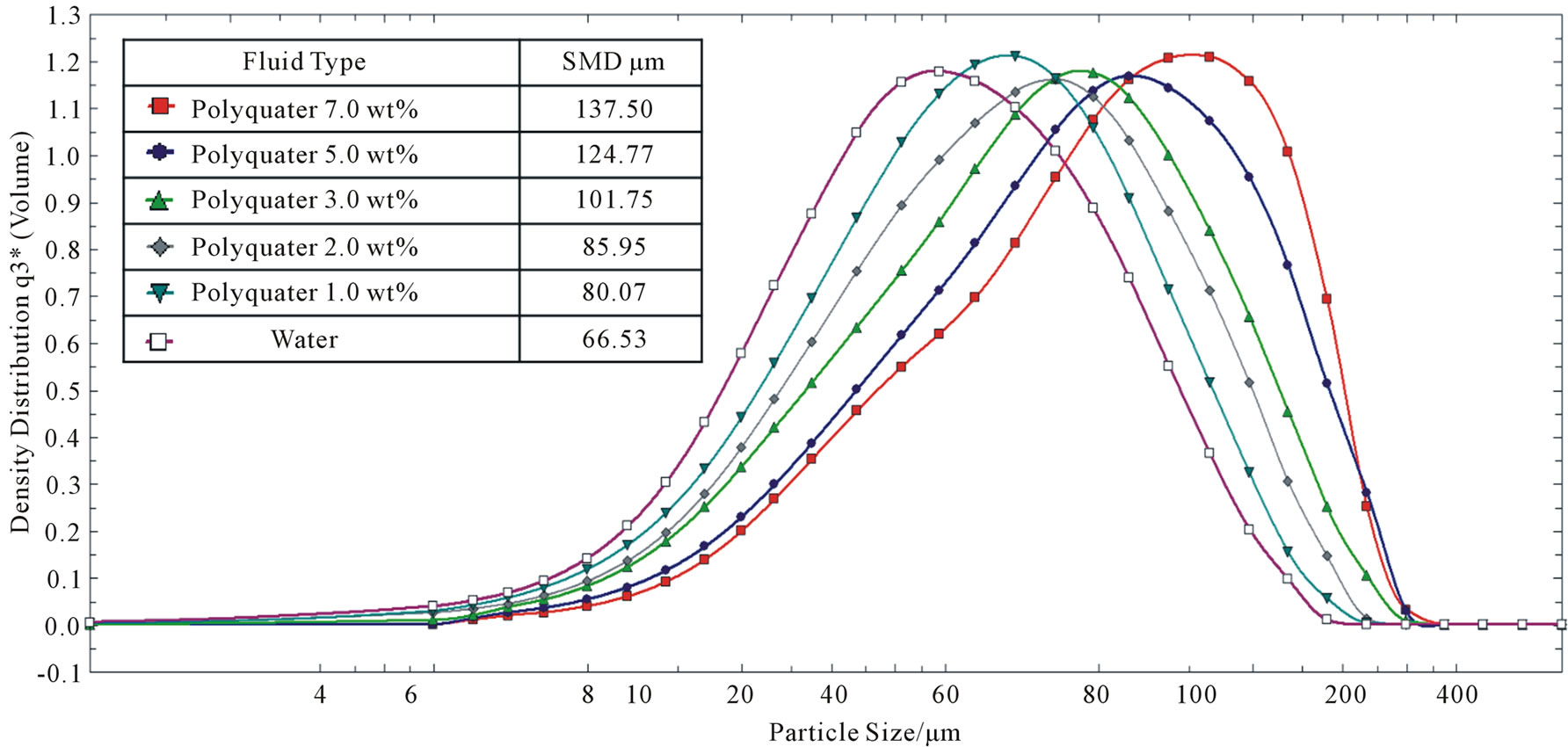
Figure 9. Supersonic liquid jets SMD profile with various non-Newtonian fluid viscosities.
occurred at with the leading edge shock wave and compression waves in front of the jets were observed. Also, the shock wave significantly affected the atomization process for each spray droplet. As a result, it was found that the maximum jet Reynolds number appeared in the liquid jet of high viscosity properties of polyquater with 7.0 wt%. A higher viscosity can achieve poorer atomization characteristics. However, a higher viscosity can achieve longer penetration characteristics.
5. Acknowledgements
This work was supported by the Korea Research Foundation Grant Funded by the Korean Government (KRF- 2009-0087898).
REFERENCES
- D. C. Jenkens, “Erosion of Surfaces by Liquid Drops,” Nature, Vol. 176, 1955, pp. 303-304. doi:10.1038/176303a0
- W. C. Cooley, “Survey of Water Jet Coal Mining Technology,” Third International Symposium on Jet Cutting Technology, Chicago, 1976, pp. D1-1.
- T. J. Labus, “Cutting and Drilling of Composites Using High Pressure Water Jets,” Fourth International Symposium on Jet Cutting Technology, Canterbury, 12-14 April 1978, pp. G2-G9.
- S. Kook and L. M. Pickett, “Effect of Ambient Temperature and Density on Shock Wave Generation in a Diesel Engine,” Atomization and Sprays, Vol. 20, No. 2, 2010, pp. 163-175. doi:10.1615/AtomizSpr.v20.i2.50
- H. Akiyama, H. Nishimura, Y. Ibaraki and N. Iida, “Study of Diesel Spray Combustion and Ignition Using High-Pressure Fuel Injection and a Micro-Hole Nozzle with a Rapid Compression Machine: Improvement of Combustion Using Low Cetane Number Fuel,” JSAE Review, Vol. 19, No. 4, 1998, pp. 319-327. doi:10.1016/S0389-4304(98)00024-1
- H.-H. Shi and K. Takayama, “Generation of Hypersonic Liquid Fuel Jets Accompanying Self-Combustion,” Shock Waves, Vol. 9, No. 5, 1999, pp. 327-332. doi:10.1007/s001930050193
- K. Pianthong, K. Takayama, B. E. Milton and M. Behnia, “Multiple Pulsed Hypersonic Liquid Diesel Fuel Jets Driven by Projectile Impact,” Shock Waves, Vol. 14, No. 1-2, 2005, pp. 73-82. doi:10.1007/s00193-004-0237-2
- J. E. Field and M. B. Lesser, “On the Mechanics of High Speed Liquid Jets,” Proceedings of the Royal Society London, A Series, Vol. 357, No. 1689, 1977, pp. 143-162.
- H. Hiroyasu, “Fundamental Spray Combustion Mechanism and Structures of Fuel Spray in Diesel Engines,” IUTAM Symposium on Mechanics and Combustion of Droplets and Sprays, Tainan, 6-10 December 1994, pp. 291-306.
- T. Nakahira, M. Komori, M. Nishida and K. Tsujimura, “The Shock Wave Generation around the Diesel Fuel Spray with High Pressure Injection,” International Congress & Exposition, Detroit, 24 February 1992, pp. 19-24. doi:10.4271/920460
- K. Pianthong, “Supersonic Liquid Diesel Fuel Jets; Generation, Shock Wave Characteristics, Auto-Ignition Feasibilities,” Ph.D. Thesis, New South Wales University, Sydney, Australia, 2002.
- H. H. Shi, H. Sato and M. Itoh, “Non-Newtonian supersonic liquid jets,” Proceedings of the 25th International Symposium on Shock Waves, Bangalore, 17-22 July 2005, pp. 1105-1110.
- F. P. Bowden and J. H. Brunton, “Damage to Solids by Liquid Impact at Supersonic Speeds,” Nature, Vol. 181, No. 4613, 1958, pp. 873-875. doi:10.1038/181873a0
- B. Natan and S. Rahimi, “The Status of Gel propellants in Year 2000,” In: (K. K. Kuo and L. T. DeLuca, Eds., Combustion of Energetic Materials, Begell House, New York, 2002, pp. 172-194.
- R. W. Dexter, “Measurement of Extensional Viscosity of Polymer Solutions and Its Effects on Atomization from a Spray Nozzle,” Atomization and Sprays, Vol. 6, No. 2, 1996, pp. 167-191.
- A. B. Metzner and J. C. Reed, “Flow of Non-Newtonian Fluids—Correlation of the Laminar, Transition, and Turbulent-Flow Regions,” A.I.Ch.E. Journal B1, Vol. 1, No. 4, 1995, pp. 434-440.