J. Biomedical Science and Engineering, 2010, 3, 517-524
doi:10.4236/jbise.2010.35072 Published Online May 2010 (http://www.SciRP.org/journal/jbise/
JBiSE
).
Published Online May 2010 in SciRes. http://www.scirp.org/journal/jbise
Time dependent dispersion of nanoparticles in blood vessels
Francesco Gentile1, Paolo Decuzzi2
1Center of Bio-Nanotechnology and -Engineering for Medicine, Università Magna Graecia, Catanzaro, Italy;
2Department of Nanomedicine and Biomedical Engineering, the University of Texas Health Science Center, Houston, USA.
Email: gentile@unicz.it
Received 25 September 2009; revised 20 October 2009; accepted 25 October 2009.
ABSTRACT
The dispersion of intravasculary injected nanoparti-
cles can be efficiently described by introducing an
effective diffusion coefficient Deff which quantifies the
longitudinal mass transport in blood vessels. Here,
the original work of Gill and Sankarasubramanian
was modified and extended to include 1) the variati-
on over time of Deff; 2) the permeability of the blood
vessels and 3) non-Newtonian rheology of blood. A
general solution was provided for Deff depending on
space (
), time (
), plug radius (
c) and a subset of
permeability parameters. It was shown that in-
creasing the vessel plug radius (thus hematocrit) or
permeability leads to a reduction in Deff, limiting
the transport of nanoparticles across those vessels. It
was also shown that the asymptotic time beyond
which the solution attains the steady state behaviour
is always independent of the plug radius and wall
permeability. The analysis presented can more accu-
rately predict the transport of nanoparticles in blood
vessels, compared to previously developed models.
Keywords: Nanoparticle Transport; Casson Fluid;
Permeable Blood Vessels; Drug Delivery
1. INTRODUCTION
The study of solute dispersion in capillaries dates back
to the celebrated works of Taylor and Aris [1,2], who
first studied the effect of shear stress on the transport in
laminar flows. They provided a solution for the classic
advection/diffusion equation
2
m
CCD C
t
 
u (1)
in the long term steady state limit, in terms of a constant
effective coefficient of diffusion as
2
1
192
e
eff m
P
DD



,
(2)
which includes the molecular diffusion contribution (
Dm) and the convective contribution ( Pe). In the Eqs.1
and 2 above, Pe (Pe = Re × u0 / Dm) is the Peclet number
for a capillary with radius Re and centerline velocity u0,
C is the local solute concentration; u is the fluid velocity
vector; Dm is the Brownian or molecular diffusion coef-
ficient and and 2 are the gradient and Laplacian op-
erators, respectively. The solution of Taylor and Aris
is valid under the simplifying assumptions of 1)
quasi-steady dispersion and 2) unidirectional flow. In
particular, it is strictly valid beyond the asymptotic time
tst = 1/2 × Re
2/Dm. Notice that sub-micrometric particles
with a molecular diffusivity Dm typically ranging be-
tween 10-11 and 10-9 m
2/s, in large vessels (Re 10-2 m)
would have tst of the order of 105 -107 s, whereas in small
capillaries (Re 10-6 m) tst would fall in the range
10-3-10-1 s.
Considerable efforts were expended in the attempt
of relaxing the above assumptions. Gill [3] extended
Taylor’s formulation to obtain the local concentration C
by means of a series expansion about the mean concen-
tration, leading to the Generalized Dispersion Model
(GDM), founding upon the rephrased convective-
diffusive equation
0
()
i
m
ii
i
Kt
τς
m

(3)
where Ki(t) are suitable functions of time; m is the
normalized concentration averaged over a cross section
of the capillary as explained in the sequel,
and
are
the longitudinal and time coordinates respectively. San-
karasubramanian and Gill [4] further developed the GD-
M including the effect of wall permeability to the solute
(i.e. nanoparticles). In 1993, Sharp derived explicit expr-
essions for the constant steady state coefficient Deff for a
non-Newtonian fluid considering, in particular, a Cas-
son-like fluid [5]. Dash et al. [6] and Nagarani et al. [7]
combined the model of Sharp and the GDM to obtain the
unsteady dispersion in a Casson-like fluid, introducing
solute adsorption to the walls. More recently, Decuzzi
et al. [8] revisited the theory of Taylor and Aris incor-
porating the effects of wall permeability for the working
fluid (plasma) and deriving a novel and more general
518 F. Gentile et al. / J. Biomedical Science and Engineering 3 (2010) 517-524
Copyright © 2010 SciRes. JBiSE
expression for Deff being
2
0
1,
192
e
eff m
P
DDf z




, (4)
where P is the Peclet number at the entrance of the
capillary (
0
e
0
~
z), and f is a function of the permeability
parameter , pressure parameters , and longitudinal
coordinate
z
~
along the capillary, as described in the
sequel. In 2008, Gentile et al. [9] expanded the solution
in [8] to include a Casson-like model for the fluid. Noti-
ceably, the models presented in [8] and [9] are valid in
the limit of large times of dispersion or, equivalently, at
the steady state. No explicit dependency on time was
introduced and the solution was deduced in terms of the
longitudinal space coordinate solely.
In this work, the transport formulation proposed in [9]
was further developed to account for the time dependency of
the problem. The transport of nanoparticles was investigated
and the effective diffusion coefficient Deff derived. Deff
would in general depend upon the permeability of the capil-
lary and the rheology of blood as in [9], but this dependency
was extended to all times, thus also comprising the initial
regime of dispersion. The model presented herein comprises,
in the limits, well established schemes of diffusion.
2. MATERIALS AND METHODS
A circular capillary with radius Re and length l was con-
sidered as in Figure 1. A Casson-like fluid was conside-
red with capillary walls permeable to the fluid, imperme-
able and not adsorbent to the solute (i.e. nanoparticles).
In the following of the paper, the Generalized Dispersion
Model was recalled and revised.
2.1. The Governing Equations
Following [4], the dispersion of a solute in a cylindrical
capillary was described by the normalized advection-dif-
fusion equation


2
2
2
0
11

eP (5)
Figure 1. Longitudinal transport of molecules or nanoparticles
in a blood capillary with a blunted velocity profile.
with the non dimensional terms being
00
22
0
;;
;;
e
mm
ee
Cu
υρ
Cu R
Dz Dt
ςτ
Ru R
  

;
r
(6)
where C is the local concentration of the solute and C0 a
reference concentration, u0 is the initial center line velo-
city at the inlet and u the velocity distribution within the
capillary with radius Re, Dm is the molecular diffusivity
of the solute, r and z are the radial and longitudinal co-
ordinates as from the frame of reference in Figure 1, and
t stays for the dimensional time. In Eq.6 P (= Re ×
u0/Dm) is the characteristic Peclet number defined as
above. It was assumed that the particles are sufficiently
small to have the same velocity of the dislodging fluid so
that the diffusion/advection problem and the fluid-dy-
namic problem may be treated separately. The solution
of Eq.5 for can be derived exactly as
0
e

0
,;
i
m
ii
i
fρςτς


(7)
where the functions fi were related to the i-th derivative
of m as shown in the sequel. The mean concentration
m was defined as
.2 1
0

d
m
(8)
From Eqs.5 and 7, it follows that m has to satisfy the
relation
i
m
i
i
i
mK



0
(9)
where the dispersion coefficients Ki were defined prop-
erly as function of time as to give
2
2
0
1
1
0
(,)2(1,;)
2(,;)(,)
ii
i
e
i
δf
Kςτ ςτ
ρP
fρςτυρς ρd
ρ
 

(10)
with the understanding that f0 = 1 and f1 = 0. Here
i2
denotes the delta of Kronecker. The dispersion problem
was thus reduced to estimating fi and Ki for each i. The
auxiliary functions fi must satisfy the differential equa-
tions
.
1
0
2
2
1
0
ini
i
e
n
n
nn fK
P
f
f
ff




(11)
Relations Eq.10 and Eq.11 are coupled, and their so-
lution becomes untractable of i > 2. Nevertheless it was
shown [10] that all terms involving a coefficient higher
than i = 2 in Eq. 10 can be neglected, in that K2 is more
than two orders of magnitude greater than K3. Eq.9 thus
F. Gentile et al. / J. Biomedical Science and Engineering 3 (2010) 517-524 519
Copyright © 2010 SciRes. JBiSE
reduces to the simplified relation
2
2
21



mm KK 
m (12)
where K1 and K2 represent the convective and diffusive
rmeable
The ution in the capillary was given for a
term, respectively. Notice that Ki and fi depend upon the
velocity field in the capillary


.
2.2. The Velocity Distribution in Pe
Capillaries
velocity distrib
Casson-like fluid by [9]


c
c
cc
ccc ξξξ
d
d






for
for
121
3
8
1
3
1
2
3
8
1
2/12/32
22/1
(13)
where
c is the ratio between the plug radius rc and the
radius of the capillary Re (
c = rc/Re) and d
d
is the
pressure gradient along
. From Eq.13 the non dimen-
sional flow rate was derived through integration over the
cross section to give

,
2
)(2 1
0c
A
d
d
dr


 (14)
where

,
21
1
3
4
7
16
14
cccc
A

 (15)
and the mean fluid velocity could be written as

1.
dχAξ
 
2c
πdς (16)
In the limit of a Newtonian fluid (
c0), Eq.1 6 yields
th
aries,
e expected value 0.5 .
In permeable capillthe fluid flows laterally across
the walls inducing a continuos reduction in mean fluid ve-
locity along the capillary. Following [8,9], the normalized
mean fluid velocity was expressed as a function of the
hydraulic conductivity Lp, the interstitial fluid pressure
i,
the inlet and the outlet vascular pressures p0 and p1, giving



 




1dχ
2
cosh cosh,
2
1cosh
c
ccc
c
c
Aξ
dς
κς ξξκς ξAξ
ξ


 
(17)
where is a non dimensional pressure parameter
0/1
;
i
pπ

1/1
i
pπ (18)
(
c) is the permeability parameter given by
 
41 .
lη (19)
Notice that differently from [8], the perme
rameter is not fixed and varies with
c. Substituting
ba
rticles is introduced
e t = 0
cp
ee cc
ξL
RR AξAξ

ability pa-
ck the Eqs.17 and 13 to Eqs.10 and 11, the coeffi-
cients Ki were appropriately derived.
2.3. The Initial and Boundary Conditions
It was assumed that a bolus of nanopa
instantaneously and uniformly at the initial tim
into the capillary, that is

.0;0;,
m
(20)
In addition, the walls are impermeable to the solute
and no absorption occurs to lead to
,0
1

(21)
symmetry at the centerline imposed
,0
0
 (22)
and finally mass conser
matical terms as
vation was translated in mathe-
.0;0
;0 


 m
i
i



i
i
m
i
(23)
The above relations should be also rephrased in terms
of fi to solve Eq.11 , giving [4,6,7]
.0 ,0 ,
0
1
0

ff
df ii
01


(24)
2.4. Solution for K1 and f1
Imposing n = 1 in Eq.11, it was derived
,
1
11 K


1ff  (25)
and multiplying by
and integrating w
from 0 to 1, invoking the first of Eq.24, it
From Eq.26, it was deduced that
K1 equals the mean velocity
al
ith respect to
followed that

.2 1
0
1

dvK (26)
the convective term
that is not constant
ong the capillary. Also notice that assuming a frame of
reference moving with ,
K1 would be zero as in [6]. f1
was found as a solution of the partial differential Eq.25
520 F. Gentile et al. / J. Biomedical Science and Engineering 3 (2010) 517-524
Copyright © 2010 SciRes. JBiSE
that can be decomposed as the sum the steady state solu-
tion f1s(

) and the transient term f1t(


).

.;,,;, 111
ts fff
(27)
Substitution of the steady state term f1s in
to Eq.25
yield
;
11

s
f (28)
which holds in the core of the capillary (
<
), where
the velocity is blunted, and in the
where the velocity varies with
. At the interface,
=
,
c
cell free layer (
>
c),
c
continuity imposed that f1s (
=
c-) = f1s (
=
c
+) which,
together with the boundary conditions Eq.24, allowed
the deconvolution of f1s as
  


c
c
c
ccc
s
f
C
B








cosh1
coshcosh
,
1
for
for
)(
)(
(2)
where B and C are solely functions of
:
9
,
194040
)ln(2310
194040
)14566421(1155147
194040
143015092216008085
);(
4
2422/16
42/1
cc
ccccc
ccc


c
B




(30)

).ln(
841320
336
)32(
))32(107(
)8815445(
1617
4
362
48
1
);(
46
4
2
2
2/12/72
42
r
Cc








(31)
The transient term f1t depends upon f1s and was readily
derived as [6]

 


n
sn
nJe
J
dfJ n
0
2
10
0
2
(32)

n0
,
where J0 and J1 are the Bessel function of first type and
order zero and one, respectively, and the
were found as the roots of the equation J (
) = 0.
0 to 1, K2 was obtained as
eigenvalues
n
1n
2.5. Solution for K2
Imposing n = 2 in Eq.11, multiplying by
and integrat-
ing with respect to
from
 

df
Pe
K,;,2
1
;1
1
0
2
0
2
 (33)
notice that, differently from the original formu
Gill and Sankarasubramanian [4,10], the auxil
lation by
iary func-
tions K2 would in general depend also on the longitudi-
nal coordinate
and, in particular, the problem would be
determined if the velocity field in the capillary is known.
In the limit of large time K2 is found as
 








cccccc
cccc
cccc
cccc
c
cc
Pe





ln
147
8
147
4
1155
872
21
64
147
512
66885
430331
165
6976
1155
55808
165
11464
21
4096
2205
385312
3773
272128
21
244
45
128
715
6144
56595
558368
1555
5888
1
cosh1192
8121092/17
872/136
2/1152/94
22/32/1
2
0
(34)
thus recovering the results derived in [9]. Incidentally
notice that Eq.34 represents the most general form
ient for estimating the transp-
ive diffusion


c
K

coshcosh11
2
ula-
n K tion for the non dimensional coefficient of diffusio2
in that it comprises an extensive subset of solutions, de-
pending on the rheological parameters
c, and . In
particular, as (or, equivalently, ) goes to zero (im-
permeable capillary) Eq.34 coincides with the relation
given in [5], whereas as the rheological parameter
c
goes to zero the result given by [8] is recovered. The
classical solution of Taylor and Aris [1,2] is found when
both () and
c are null.
3. RESULTS AND DISCUSSION
The most important coeffic
ort of nanoparticles is the normalized effect
coefficient
 
2
2
2
2
2
1AA
D
Kcc
eff

 (35)
0
Pe
A
Dc
m

in that it gives a measure of the propensit
cles to spread about their center of mass a
y of the parti-
long the capil-
lary. Differently from all the schemes proposed so far,
the K2 presented in Eq.35 changes with
due to the
variation of the mean fluid velocity along the permeable
vessel. In Figure 2 the relation 192(K2Pe
-2) was plot-
ted as a function of
and
in the case of large perme-
ability of the walls (= 8, = –2) and for a Newtonian
F. Gentile et al. / J. Biomedical Science and Engineering 3 (2010) 517-524 521
Copyright © 2010 SciRes.
t
a
fluid (
c = 0). Generally K2 increases with time and attains
the steady state value after the early stage of dispersion
which corresponds to
= 0.5. A central position of the ves-
sel was observed where K2Pe
-2 = 0, implying that in such
area dispersion is solely driven by pure molecular diffusion.
The decrease of K2 with
strongly depends upon the per-
meability of the capillary () and the plug radius of the
fluid (
c). In Figure 3 the 3D plot of the relation 192(K2
Pe
-2) as a function of time
and position along the capillary
was displayed showing the effects of and
c varying
between 0 and 4 and 0 and 0.4 respectively, and for a con-
stant = –2. In Figure 4, the contourplots corresponding
o Figure 3 were reported. As time increases, the solution
for K2 tends to a constant asymptotic value. Noticeably, the
time beyond which dispersion turns to be time independent
is always less than 0.5, regardless and
c Therefore, the
permeability parameter and the plug radius have a negligi-
ble effect upon the process of diffusion along with time but
do effect on the steady state behavior of the system. In par-
ticular, when both and
c are larger than zero the reduc-
tion in dispersion (Deff or K2) is dramatic, and in large por-
tions of the capillary the transport of the nanoparticles is
mostly diffusion limited. This is easily explained observing
that longitudinal transport is enhanced by radial velocity
gradients (shear diffusion), thereby either an increase of the
core region of the capillary with a flat velocity profile (thus
c) or a reduction in the velocity amplitude due to an aug-
mented permeability (thus ), generates a decrease in K2,
s thoroughly discussed in [8,9].
Figure 2. The dimensionless effective diffusion K2 as
a function of the normalized position (
) and time (
)
for a fixed plug radius
c = 0 and for a permeable cap-
illary (= 8, = –2).
Figure 3. 3D plots of the dimensionless effective diffusion coefficients K2 as a
function of the normalized position (
) and time (
), for and
varying be
-
c
tween 0 and 4, and 0 and 0.4 respectively, and for a constant = –2.
JBiSE
522 F. Gentile et al. / J. Biomedical Science and Engineering 3 (2010) 517-524
Copyright © 2010 SciRes. JBiSE
Figure 4. Contour plots of the dimensionless effective diffusion coefficients K2 as a function of the
normalized position (
) and time (
), for and
c varying between 0 and 4, and 0 and 0.4 respectively,
Given K2, thefficient Deff was
educed as
and for a constant = –2.
e effective diffusion co
d
 

,
2
2
2m
cmc
eff D
A
K
DA


or, equivalently
1
2
2
0
2
ce AuR
D
(36)


.
1
2
2
2
2
2
0
c
c
c
m
eff
DA
A
K
A
P
D
e
(37)
Eq.37 shows that any enhancemen
fusion over the Brownian diffusion (D) is proportional
to
t values of
P
from 0 to 0.4, at large times the classical solutions of Taylor
and Aris [1,2] (
= 0), and Sharp [4] (
= 0.2, 0.4) are
t in effective dif-
m
the product P0
e × K2 and would strongly depend on
the local hydrodynamics and capillary size.
The dimensionless effective diffusion Deff/Dm as a func-
tion of the rheological parameter
, for differen
c
e and for a fixed = 0 was shown in Figure 5. As ex-
pected, confirming the results derived in [9], larger Pe and
smaller
c lead to larger Deff/Dm ratios. Figure 6 illustrated
the ratio Deff/Dm over time, for an impermeable channel
(= 0) and for different values of
c. Figure 7 reported the
same diagram of Figure 6 for a permeable channel (= 2,
= –2). In all cases, a steady state value was attained for
larger than 0.5. Notice that for = 0 and for
c moving
c c
recovered (Figure 6).When the permeable solution was
instead considered (Figure 7), the steady state values reca-
pitulated the results given by Decuzzi et al. [8] (
c = 0) and
Gentile et al. [9] (
c = 0.2, 0.4).
Figure 5. The dimensionless effective diffusion (Deff/Dm) as a
function of the rheological parameter
c, for different values of
Pe and for a fixed = 0.
F. Gentile et al. / J. Biomedical Science and Engineering 3 (2010) 517-524 523
Copyright © 2010 SciRes. JBiSE
Figure 6. The ratio (Deff/Dm) over time, for a permeable cha-
nnel (= 0) and for different values of
c.
Figure 7. The ratio (Deff/Dm) over time, for a permeable chan-
nel (= 2; = –2) and for different values of
c.
Table 1. Average dimensions and velocities of blood vessels
(Decuzzi, 2006 [8]). Pe is calculated for Dm = 6 × 10-13 m2/s.
Vessel ]mm[L ]mm[
e
R ]s/mm[U Pe
Aorta 50 25 400 1.6 × 10¹⁰
Artery 2-1.5 4 100 6.67 × 10⁸
Arteriole 2-1.5 0.1-0.02 5 1.67 - 8.33 × 10⁵
Capillary 0.5 0.001-0.005 1-0.1 41667 -833
Venules 1 0.05 -0.02 0.5 1.66 - 4.16 × 10⁴
Vein 14 -1 5-2 50 1.6 - 4.1 × 10⁸
Vena
Cava 50 -40 30 100 5 × 10⁹
Recalling that the width of the plug radius
c scales
ith Re as
c ~ 1-3 × Re
-0.8 [9] and considering the data of
g-
morespce cell f layer
are owednimulue thateff/Dm
would assumea vessethe steatate an
offlug radius
c forpers-
s0). e 9d the same d
pe ve ( –t wa
w
Table 1, moving from capillaries to arterioles and venu-
les P0
e significantly increases and the ratio Deff/Dm au
ents acc
a. Figure
dingly d
8 sh
ite a redu
the mi
tion of th
m va
ree
D
in l at dy ss a functio
Re and o the p an immeable ve
el (= Figur reporteiagram for a
= 5, =2). Is observed
ermeabl ssel
Figure 8. The minimum value that Deff/Dm would assume
in a vessel at the steady state as a function of Re and of the
plug radius
c; for an impermeable vessel (= 0).
Figure 9. The minimum value that Deff/Dm would as-
sume in a vessel at the steady state as a function of Re
and of the plug radius
c; for a permeable vessel (= 5,
= –2).
524 F. Gentile et al. / J. Biomedical Science and Engineering 3 (2010) 517-524
Copyright © 2010 SciRes.
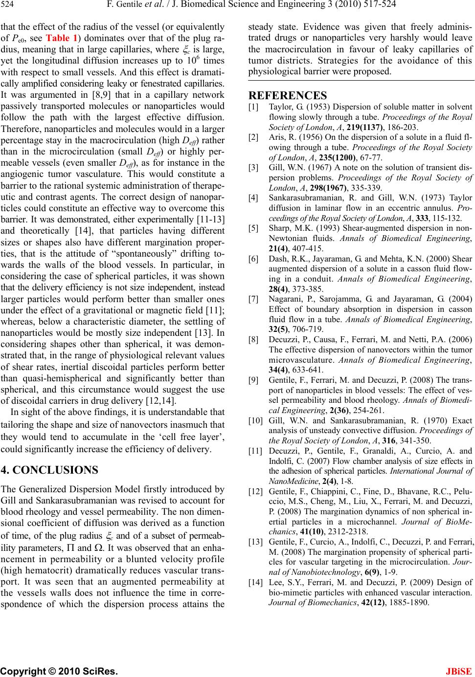
that the effect of the radius of the vessel (or equivalently
of Pe0, see Table 1) dominates over that of the plug ra-
dius, meaning that in large capillaries, where
c is large,
yet the longitudinal diffusion increases up to 106 times
with respect to small vessels. And this effect is dramati-
cally amplified considering leaky or fenestrated capillaries.
It was argumented in [8,9] that in a capillary network
passively transported molecules or nanoparticles would
follow the path with the largest effective diffusion.
Therefore, nanoparticles and molecules would in a larger
percentage stay in the macrocirculation (high Deff) rather
than in the microcirculation (small Deff) or highly per-
meable vessels (even smaller Deff), as for instance in the
angiogenic tumor vasculature. This would constitute a
barrier to the rational systemic administration of therape-
utic and contrast agents. The correct design of nanopar-
ticles could constitute an effective way to overcome this
barrier. It was demonstrated, either experimentally [11-13]
and theoretically [14], that particles having differen
si r-
tie -
wn
ould leave
th
REFERENCES
rsion of soluble matter in solvent
Proceedings of the Royal
ayaraman, G. (2004)
be. Annals of Biomedical Engineering,
JBiSE
t
zes or shapes also have different margination prope
s, that is the attitude of “spontaneously” drifting to
ards the walls of the blood vessels. In particular, i
considering the case of spherical particles, it was shown
that the delivery efficiency is not size independent, instead
larger particles would perform better than smaller ones
under the effect of a gravitational or magnetic field [11];
whereas, below a characteristic diameter, the settling of
nanoparticles would be mostly size independent [13]. In
considering shapes other than spherical, it was demon-
strated that, in the range of physiological relevant values
of shear rates, inertial discoidal particles perform better
than quasi-hemispherical and significantly better than
spherical, and this circumstance would suggest the use
of discoidal carriers in drug delivery [12,14].
In sight of the above findings, it is understandable that
tailoring the shape and size of nanovectors inasmuch that
they would tend to accumulate in the ‘cell free layer’,
could significantly increase the efficiency of delivery.
4. CONCLUSIONS
The Generalized Dispersion Model firstly introduced by
Gill and Sankarasubramanian was revised to account for
blood rheology and vessel permeability. The non dimen-
sional coefficient of diffusion was derived as a function
of time, of the plug radius
c and of a subset of permeab-
ility parameters, and . It was observed that an enha-
ncement in permeability or a blunted velocity profile
(high hematocrit) dramatically reduces vascular trans-
port. It was seen that an augmented permeability at
the vessels walls does not influence the time in corre-
spondence of which the dispersion process attains the
steady state. Evidence was given that freely adminis-
trated drugs or nanoparticles very harshly w
e macrocirculation in favour of leaky capillaries of
tumor districts. Strategies for the avoidance of this
physiological barrier were proposed.
[1] Taylor, G. (1953) Dispe
flowing slowly through a tube.
Society of London, A, 219(1137), 186-203.
[2] Aris, R. (1956) On the dispersion of a solute in a fluid fl-
owing through a tube. Proceedings of the Royal Society
of London, A, 235(1200), 67-77.
[3] Gill, W.N. (1967) A note on the solution of transient dis-
persion problems. Proceedings of the Royal Society of
London, A, 298(1967), 335-339.
[4] Sankarasubramanian, R. and Gill, W.N. (1973) Taylor
diffusion in laminar flow in an eccentric annulus. Pro-
ceedings of the Royal Society of London, A, 333, 115-132.
[5] Sharp, M.K. (1993) Shear-augmented dispersion in non-
Newtonian fluids. Annals of Biomedical Engineering,
21(4), 407-415.
[6] Dash, R.K., Jayaraman, G. and Mehta, K.N. (2000) Shear
augmented dispersion of a solute in a casson fluid flow-
ing in a conduit. Annals of Biomedical Engineering,
28(4), 373-385.
[7] Nagarani, P., Sarojamma, G. and J
Effect of boundary absorption in dispersion in casson
fluid flow in a tu
32(5), 706-719.
[8] Decuzzi, P., Causa, F., Ferrari, M. and Netti, P.A. (2006)
The effective dispersion of nanovectors within the tumor
microvasculature. Annals of Biomedical Engineering,
34(4), 633-641.
[9] Gentile, F., Ferrari, M. and Decuzzi, P. (2008) The trans-
port of nanoparticles in blood vessels: The effect of ves-
sel permeability and blood rheology. Annals of Biomedi-
cal Engineering, 2(36), 254-261.
[10] Gill, W.N. and Sankarasubramanian, R. (1970) Exact
analysis of unsteady convective diffusion. Proceedings of
the Royal Society of London, A, 316, 341-350.
[11] Decuzzi, P., Gentile, F., Granaldi, A., Curcio, A. and
Indolfi, C. (2007) Flow chamber analysis of size effects in
the adhesion of spherical particles. International Journal of
NanoMedicine, 2(4), 1-8.
[12] Gentile, F., Chiappini, C., Fine, D., Bhavane, R.C., Pelu-
ccio, M.S., Cheng, M., Liu, X., Ferrari, M. and Decuzzi,
P. (2008) The margination dynamics of non spherical in-
ertial particles in a microchannel. Journal of BioMe-
chanics, 41(10), 2312-2318.
[13] Gentile, F., Curcio, A., Indolfi, C., Decuzzi, P. and Ferrari,
M. (2008) The margination propensity of spherical parti-
Jou
cles for vascular targeting in the microcirculation. Jour-
nal of Nanobiotechnology, 6(9), 1-9.
[14] Lee, S.Y., Ferrari, M. and Decuzzi, P. (2009) Design of
bio-mimetic particles with enhanced vascular interaction.
rnal of Biomechanics, 42(12), 1885-1890.