Paper Menu >>
Journal Menu >>
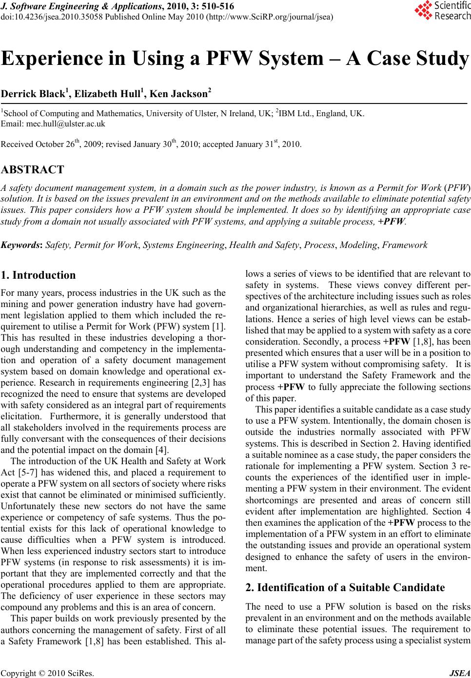 J. Software Engineering & Applications, 2010, 3: 510-516 doi:10.4236/jsea.2010.35058 Published Online May 2010 (http://www.SciRP.org/journal/jsea) Copyright © 2010 SciRes. JSEA Experience in Using a PFW System – A Case Study Derrick Black1, Elizabeth Hull1, Ken Jackson2 1School of Computing and Mathematics, University of Ulster, N Ireland, UK; 2IBM Ltd., England, UK. Email: mec.hull@ulster.ac.uk Received October 26th, 2009; revised January 30th, 2010; accepted January 31st, 2010. ABSTRACT A safety document management system, in a domain such as the power industry, is known as a Permit for Work (PFW) solution. It is based on the issues prevalent in an environment and on the methods available to eliminate potential safety issues. This paper considers how a PFW system should be implemented. It does so by identifying an appropriate case study from a domain not usually associated with PFW systems, and applying a suitable process, +PFW. Keywords: Safety, Permit for Work, Systems Engineering, Health and Safety, Process, Modeling, Framework 1. Introduction For many years, process industries in the UK such as the mining and power generation industry have had govern- ment legislation applied to them which included the re- quirement to utilise a Permit for Work (PFW) system [1]. This has resulted in these industries developing a thor- ough understanding and competency in the implementa- tion and operation of a safety document management system based on domain knowledge and operational ex- perience. Research in requirements engineering [2,3] has recognized the need to ensure that systems are developed with safety considered as an integral part of requirements elicitation. Furthermore, it is generally understood that all stakeholders involved in the requirements process are fully conversant with the consequences of their decisions and the potential impact on the domain [4]. The introduction of the UK Health and Safety at Work Act [5-7] has widened this, and placed a requirement to operate a PFW system on all sectors of society where risks exist that cannot be eliminated or minimised sufficiently. Unfortunately these new sectors do not have the same experience or competency of safe systems. Thus the po- tential exists for this lack of operational knowledge to cause difficulties when a PFW system is introduced. When less experienced industry sectors start to introduce PFW systems (in response to risk assessments) it is im- portant that they are implemented correctly and that the operational procedures applied to them are appropriate. The deficiency of user experience in these sectors may compound any problems and this is an area of concern. This paper builds on work previously presented by the authors concerning the management of safety. First of all a Safety Framework [1,8] has been established. This al- lows a series of views to be identified that are relevant to safety in systems. These views convey different per- spectives of the architecture including issues such as roles and organizational hierarchies, as well as rules and regu- lations. Hence a series of high level views can be estab- lished that may be applied to a system with safety as a core consideration. Secondly, a process +PFW [1,8], has been presented which ensures that a user will be in a position to utilise a PFW system without compromising safety. It is important to understand the Safety Framework and the process +PFW to fully appreciate the following sections of this paper. This paper identifies a suitable candidate as a case study to use a PFW system. Intentionally, the domain chosen is outside the industries normally associated with PFW systems. This is described in Section 2. Having identified a suitable nominee as a case study, the paper considers the rationale for implementing a PFW system. Section 3 re- counts the experiences of the identified user in imple- menting a PFW system in their environment. The evident shortcomings are presented and areas of concern still evident after implementation are highlighted. Section 4 then examines the application of the +PFW process to the implementation of a PFW system in an effort to eliminate the outstanding issues and provide an operational system designed to enhance the safety of users in the environ- ment. 2. Identification of a Suitable Candidate The need to use a PFW solution is based on the risks prevalent in an environment and on the methods available to eliminate these potential issues. The requirement to manage part of the safety process using a specialist system 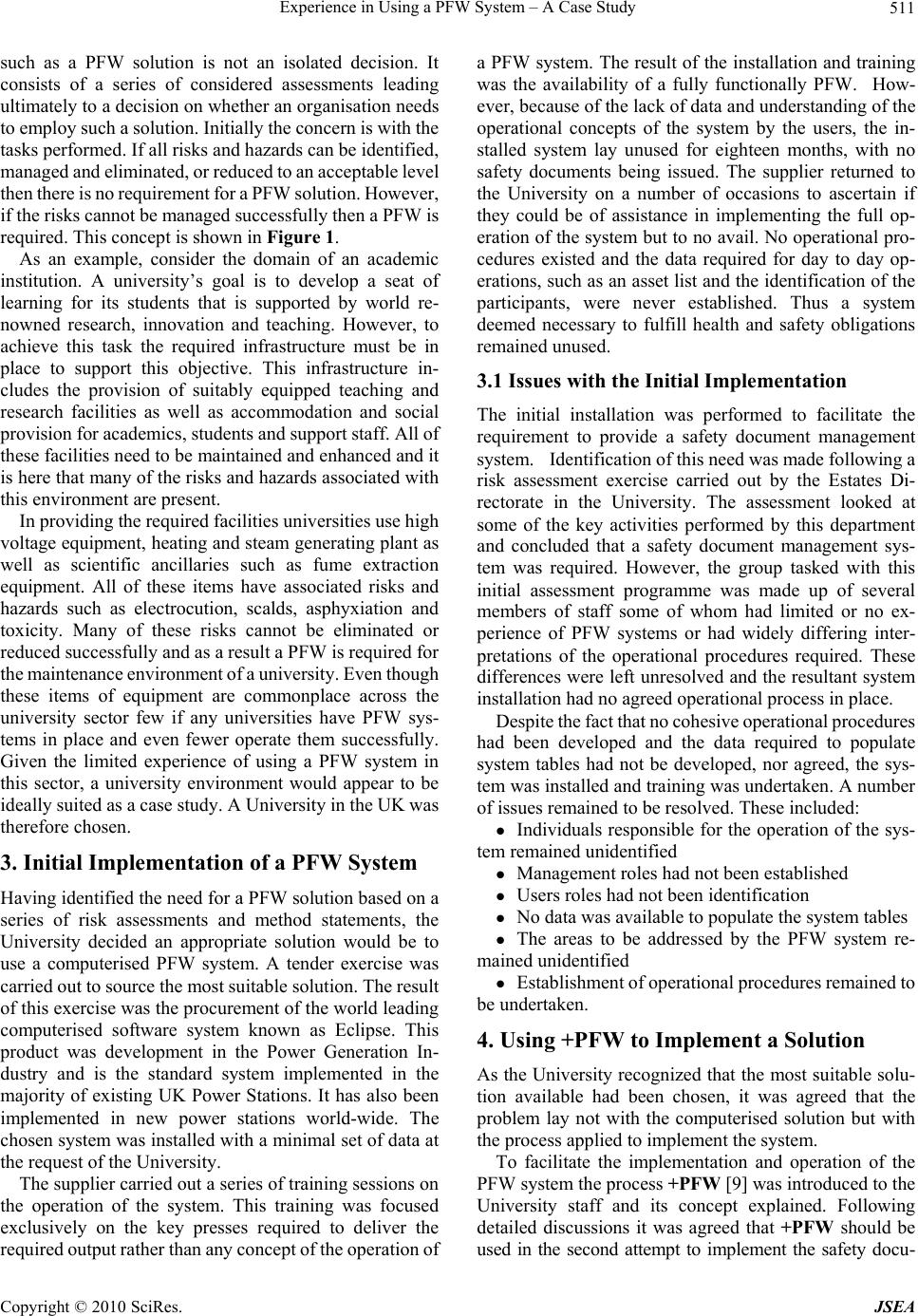 Experience in Using a PFW System – A Case Study Copyright © 2010 SciRes. JSEA 511 such as a PFW solution is not an isolated decision. It consists of a series of considered assessments leading ultimately to a decision on whether an organisation needs to employ such a solution. Initially the concern is with the tasks performed. If all risks and hazards can be identified, managed and eliminated, or reduced to an acceptable level then there is no requirement for a PFW solution. However, if the risks cannot be managed successfully then a PFW is required. This concept is shown in Figure 1. As an example, consider the domain of an academic institution. A university’s goal is to develop a seat of learning for its students that is supported by world re- nowned research, innovation and teaching. However, to achieve this task the required infrastructure must be in place to support this objective. This infrastructure in- cludes the provision of suitably equipped teaching and research facilities as well as accommodation and social provision for academics, students and support staff. All of these facilities need to be maintained and enhanced and it is here that many of the risks and hazards associated with this environment are present. In providing the required facilities universities use high voltage equipment, heating and steam generating plant as well as scientific ancillaries such as fume extraction equipment. All of these items have associated risks and hazards such as electrocution, scalds, asphyxiation and toxicity. Many of these risks cannot be eliminated or reduced successfully and as a result a PFW is required for the maintenance environment of a university. Even though these items of equipment are commonplace across the university sector few if any universities have PFW sys- tems in place and even fewer operate them successfully. Given the limited experience of using a PFW system in this sector, a university environment would appear to be ideally suited as a case study. A University in the UK was therefore chosen. 3. Initial Implementation of a PFW System Having identified the need for a PFW solution based on a series of risk assessments and method statements, the University decided an appropriate solution would be to use a computerised PFW system. A tender exercise was carried out to source the most suitable solution. The result of this exercise was the procurement of the world leading computerised software system known as Eclipse. This product was development in the Power Generation In- dustry and is the standard system implemented in the majority of existing UK Power Stations. It has also been implemented in new power stations world-wide. The chosen system was installed with a minimal set of data at the request of the University. The supplier carried out a series of training sessions on the operation of the system. This training was focused exclusively on the key presses required to deliver the required output rather than any concept of the operation of a PFW system. The result of the installation and training was the availability of a fully functionally PFW. How- ever, because of the lack of data and understanding of the operational concepts of the system by the users, the in- stalled system lay unused for eighteen months, with no safety documents being issued. The supplier returned to the University on a number of occasions to ascertain if they could be of assistance in implementing the full op- eration of the system but to no avail. No operational pro- cedures existed and the data required for day to day op- erations, such as an asset list and the identification of the participants, were never established. Thus a system deemed necessary to fulfill health and safety obligations remained unused. 3.1 Issues with the Initial Implementation The initial installation was performed to facilitate the requirement to provide a safety document management system. Identification of this need was made following a risk assessment exercise carried out by the Estates Di- rectorate in the University. The assessment looked at some of the key activities performed by this department and concluded that a safety document management sys- tem was required. However, the group tasked with this initial assessment programme was made up of several members of staff some of whom had limited or no ex- perience of PFW systems or had widely differing inter- pretations of the operational procedures required. These differences were left unresolved and the resultant system installation had no agreed operational process in place. Despite the fact that no cohesive operational procedures had been developed and the data required to populate system tables had not be developed, nor agreed, the sys- tem was installed and training was undertaken. A number of issues remained to be resolved. These included: Individuals responsible for the operation of the sys- tem remained unidentified Management roles had not been established Users roles had not been identification No data was available to populate the system tables The areas to be addressed by the PFW system re- mained unidentified Establishment of operational procedures remained to be undertaken. 4. Using +PFW to Implement a Solution As the University recognized that the most suitable solu- tion available had been chosen, it was agreed that the problem lay not with the computerised solution but with the process applied to implement the system. To facilitate the implementation and operation of the PFW system the process +PFW [9] was introduced to the University staff and its concept explained. Following detailed discussions it was agreed that +PFW should be used in the second attempt to implement the safety docu- 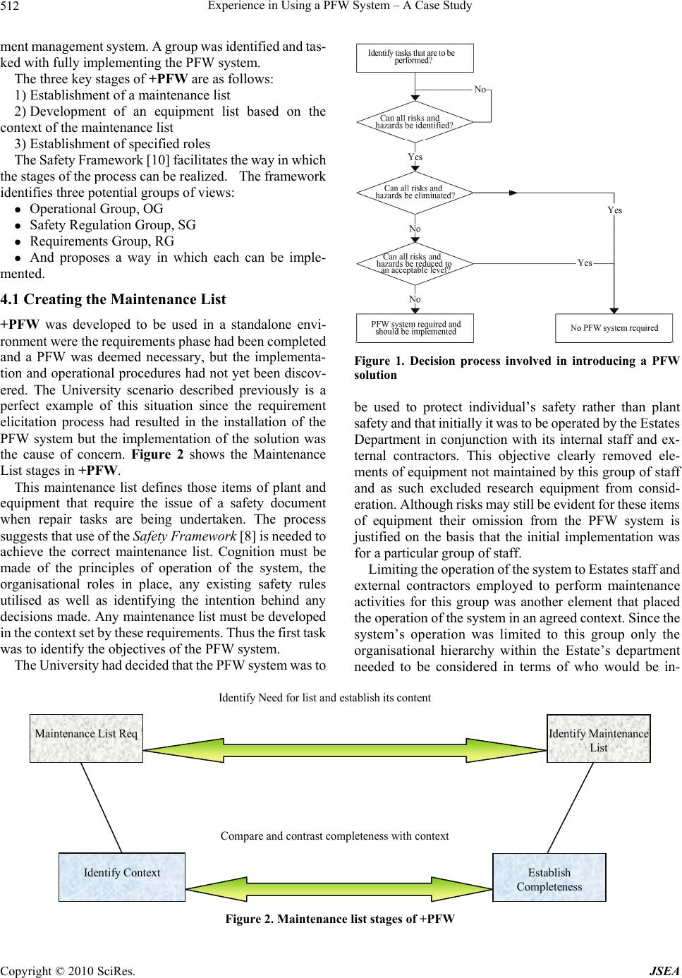 Experience in Using a PFW System – A Case Study Copyright © 2010 SciRes. JSEA 512 ment management system. A group was identified and tas- ked with fully implementing the PFW system. The three key stages of +PFW are as follows: 1) Establishment of a maintenance list 2) Development of an equipment list based on the context of the maintenance list 3) Establishment of specified roles The Safety Framework [10] facilitates the way in which the stages of the process can be realized. The framework identifies three potential groups of views: Operational Group, OG Safety Regulation Group, SG Requirements Group, RG And proposes a way in which each can be imple- mented. 4.1 Creating the Maintenance List +PFW was developed to be used in a standalone envi- ronment were the requirements phase had been completed and a PFW was deemed necessary, but the implementa- tion and operational procedures had not yet been discov- ered. The University scenario described previously is a perfect example of this situation since the requirement elicitation process had resulted in the installation of the PFW system but the implementation of the solution was the cause of concern. Figure 2 shows the Maintenance List stages in +PFW. This maintenance list defines those items of plant and equipment that require the issue of a safety document when repair tasks are being undertaken. The process suggests that use of the Safety Framework [8] is needed to achieve the correct maintenance list. Cognition must be made of the principles of operation of the system, the organisational roles in place, any existing safety rules utilised as well as identifying the intention behind any decisions made. Any maintenance list must be developed in the context set by these requirements. Thus the first task was to identify the objectives of the PFW system. The University had decided that the PFW system was to Figure 1. Decision process involved in introducing a PFW solution be used to protect individual’s safety rather than plant safety and that initially it was to be operated by the Estates Department in conjunction with its internal staff and ex- ternal contractors. This objective clearly removed ele- ments of equipment not maintained by this group of staff and as such excluded research equipment from consid- eration. Although risks may still be evident for these items of equipment their omission from the PFW system is justified on the basis that the initial implementation was for a particular group of staff. Limiting the operation of the system to Estates staff and external contractors employed to perform maintenance activities for this group was another element that placed the operation of the system in an agreed context. Since the system’s operation was limited to this group only the organisational hierarchy within the Estate’s department needed to be considered in terms of who would be in- Identify Maintenance List Establish Completeness Maintenance List Req Identify Need for list and establish its content Compare and contrast completeness with context Identify Context Figure 2. Maintenance list stages of +PFW 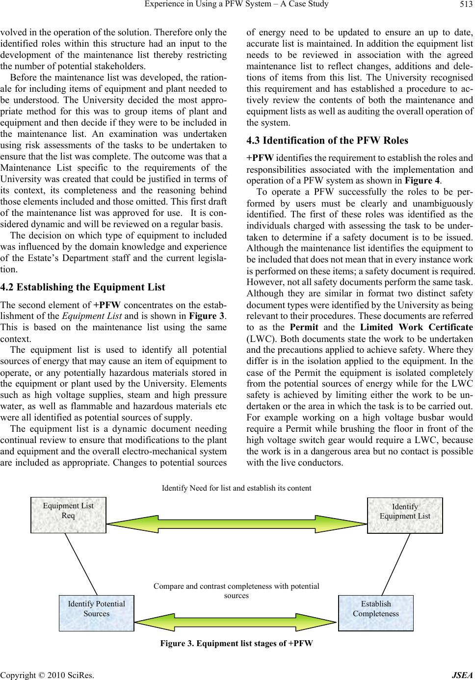 Experience in Using a PFW System – A Case Study Copyright © 2010 SciRes. JSEA 513 volved in the operation of the solution. Therefore only the identified roles within this structure had an input to the development of the maintenance list thereby restricting the number of potential stakeholders. Before the maintenance list was developed, the ration- ale for including items of equipment and plant needed to be understood. The University decided the most appro- priate method for this was to group items of plant and equipment and then decide if they were to be included in the maintenance list. An examination was undertaken using risk assessments of the tasks to be undertaken to ensure that the list was complete. The outcome was that a Maintenance List specific to the requirements of the University was created that could be justified in terms of its context, its completeness and the reasoning behind those elements included and those omitted. This first draft of the maintenance list was approved for use. It is con- sidered dynamic and will be reviewed on a regular basis. The decision on which type of equipment to included was influenced by the domain knowledge and experience of the Estate’s Department staff and the current legisla- tion. 4.2 Establishing the Equipment List The second element of +PFW concentrates on the estab- lishment of the Equipment List and is shown in Figure 3. This is based on the maintenance list using the same context. The equipment list is used to identify all potential sources of energy that may cause an item of equipment to operate, or any potentially hazardous materials stored in the equipment or plant used by the University. Elements such as high voltage supplies, steam and high pressure water, as well as flammable and hazardous materials etc were all identified as potential sources of supply. The equipment list is a dynamic document needing continual review to ensure that modifications to the plant and equipment and the overall electro-mechanical system are included as appropriate. Changes to potential sources of energy need to be updated to ensure an up to date, accurate list is maintained. In addition the equipment list needs to be reviewed in association with the agreed maintenance list to reflect changes, additions and dele- tions of items from this list. The University recognised this requirement and has established a procedure to ac- tively review the contents of both the maintenance and equipment lists as well as auditing the overall operation of the system. 4.3 Identification of the PFW Roles +PFW identifies the requirement to establish the roles and responsibilities associated with the implementation and operation of a PFW system as shown in Figure 4. To operate a PFW successfully the roles to be per- formed by users must be clearly and unambiguously identified. The first of these roles was identified as the individuals charged with assessing the task to be under- taken to determine if a safety document is to be issued. Although the maintenance list identifies the equipment to be included that does not mean that in every instance work is performed on these items; a safety document is required. However, not all safety documents perform the same task. Although they are similar in format two distinct safety document types were identified by the University as being relevant to their procedures. These documents are referred to as the Permit and the Limited Work Certificate (LWC). Both documents state the work to be undertaken and the precautions applied to achieve safety. Where they differ is in the isolation applied to the equipment. In the case of the Permit the equipment is isolated completely from the potential sources of energy while for the LWC safety is achieved by limiting either the work to be un- dertaken or the area in which the task is to be carried out. For example working on a high voltage busbar would require a Permit while brushing the floor in front of the high voltage switch gear would require a LWC, because the work is in a dangerous area but no contact is possible with the live conductors. Identify Equipment List Establish Completeness Equipment List Req Identify Potential Sources Identify Need for list and establish its content Compare and contrast completeness with potential sources Figure 3. Equipment list stages of +PFW 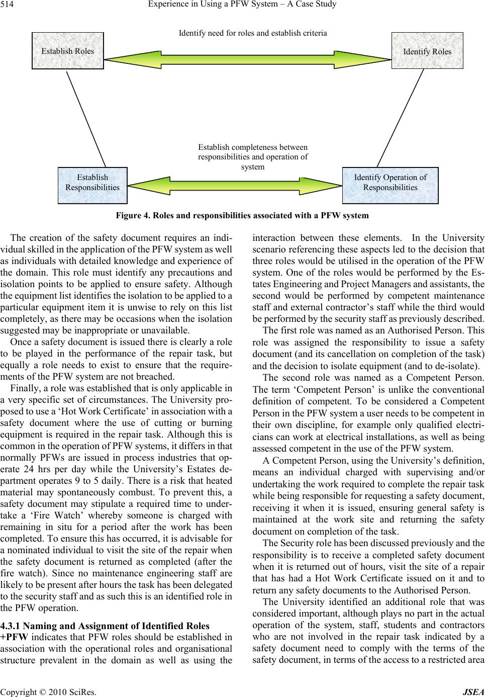 Experience in Using a PFW System – A Case Study Copyright © 2010 SciRes. JSEA 514 Identify Roles Identify Operation of Responsibilities Establish Roles Establish Responsibilities Identify need for roles and establish criteria Establish completeness between responsibilities and operation of system Figure 4. Roles and responsibilities associated with a PFW system The creation of the safety document requires an indi- vidual skilled in the application of the PFW system as well as individuals with detailed knowledge and experience of the domain. This role must identify any precautions and isolation points to be applied to ensure safety. Although the equipment list identifies the isolation to be applied to a particular equipment item it is unwise to rely on this list completely, as there may be occasions when the isolation suggested may be inappropriate or unavailable. Once a safety document is issued there is clearly a role to be played in the performance of the repair task, but equally a role needs to exist to ensure that the require- ments of the PFW system are not breached. Finally, a role was established that is only applicable in a very specific set of circumstances. The University pro- posed to use a ‘Hot Work Certificate’ in association with a safety document where the use of cutting or burning equipment is required in the repair task. Although this is common in the operation of PFW systems, it differs in that normally PFWs are issued in process industries that op- erate 24 hrs per day while the University’s Estates de- partment operates 9 to 5 daily. There is a risk that heated material may spontaneously combust. To prevent this, a safety document may stipulate a required time to under- take a ‘Fire Watch’ whereby someone is charged with remaining in situ for a period after the work has been completed. To ensure this has occurred, it is advisable for a nominated individual to visit the site of the repair when the safety document is returned as completed (after the fire watch). Since no maintenance engineering staff are likely to be present after hours the task has been delegated to the security staff and as such this is an identified role in the PFW operation. 4.3.1 Naming and Assignment of Identified Roles +PFW indicates that PFW roles should be established in association with the operational roles and organisational structure prevalent in the domain as well as using the interaction between these elements. In the University scenario referencing these aspects led to the decision that three roles would be utilised in the operation of the PFW system. One of the roles would be performed by the Es- tates Engineering and Project Managers and assistants, the second would be performed by competent maintenance staff and external contractor’s staff while the third would be performed by the security staff as previously described. The first role was named as an Authorised Person. This role was assigned the responsibility to issue a safety document (and its cancellation on completion of the task) and the decision to isolate equipment (and to de-isolate). The second role was named as a Competent Person. The term ‘Competent Person’ is unlike the conventional definition of competent. To be considered a Competent Person in the PFW system a user needs to be competent in their own discipline, for example only qualified electri- cians can work at electrical installations, as well as being assessed competent in the use of the PFW system. A Competent Person, using the University’s definition, means an individual charged with supervising and/or undertaking the work required to complete the repair task while being responsible for requesting a safety document, receiving it when it is issued, ensuring general safety is maintained at the work site and returning the safety document on completion of the task. The Security role has been discussed previously and the responsibility is to receive a completed safety document when it is returned out of hours, visit the site of a repair that has had a Hot Work Certificate issued on it and to return any safety documents to the Authorised Person. The University identified an additional role that was considered important, although plays no part in the actual operation of the system, staff, students and contractors who are not involved in the repair task indicated by a safety document need to comply with the terms of the safety document, in terms of the access to a restricted area 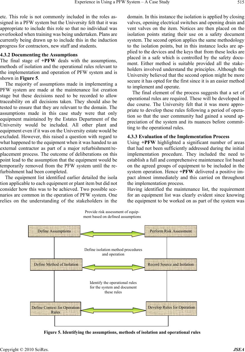 Experience in Using a PFW System – A Case Study Copyright © 2010 SciRes. JSEA 515 etc. This role is not commonly included in the roles as- signed in a PFW system but the University felt that it was appropriate to include this role so that no individual was overlooked when training was being undertaken. Plans are currently being drawn up to include this in the induction progress for contractors, new staff and students. 4.3.2 Documenting the Assumptions The final stage of +PFW deals with the assumptions, methods of isolation and the operational rules relevant to the implementation and operation of PFW system and is shown in Figure 5. The majority of assumptions made in implementing a PFW system are made at the maintenance list creation stage but these decisions need to be recorded to allow traceability on all decisions taken. They should also be tested to ensure that they are relevant to the domain. The assumptions made in this case study were that only equipment maintained by the Estates Department of the University would be included. All other plant and equipment even if it was on the University estate would be excluded. However, this raised a question with regard to what happened to the equipment when it was handed to an external contractor as part of a major refurbishment/re- placement process. The outcome of deliberations on this point lead to the assumption that the equipment would be temporarily removed from the PFW system until the re- furbishment had been completed. The equipment list identified earlier detailed the isola tion applicable to each equipment or plant item but did not consider how this was to be achieved. Two possible sce- narios are common in the operation of PFW system. One relies on the understanding of the stakeholders in the domain. In this instance the isolation is applied by closing valves, opening electrical switches and opening drain and vent valves on the item. Notices are then placed on the isolation points stating their use on a safety document system. The second option applies the same methodology to the isolation points, but in this instance locks are ap- plied to the devices and the keys that from these locks are placed in a safe which is controlled by the safety docu- ment. Either method is suitable provided all the stake- holders involved understand the principles. Although the University believed that the second option might be more secure it has opted for the first since it is an easier method to implement and operate. The final element of the process suggests that a set of operational rules are required. These will be developed in due course. The University felt that it was more appro- priate to develop these rules following a period of opera- tion so that the user community had gained a sound ap- preciation of the system and its nuances before commit- ting to the operational rules. 4.3.3 Evaluation of the Implementation Process Using +PFW highlighted a significant number of areas that had not been sufficiently addressed during the initial implementation procedure. They included the need to establish a full and comprehensive maintenance list based on the agreed groups of equipment to be included in the system operation. Hence +PFW delivered a positive im- pact almost immediately and this carried on throughout the implementation process. Having identified the maintenance list, the requirement for an equipment list was clearly evident since knowing the equipment to be worked on as part of the system was Figure 5. Identifying the assumptions, methods of isolation and operational rules Perform Risk Assessment Define Assumptions Provide risk assessment of equip- ment based on defined assumptions Record Source and Isolation Define Method of Isolation Define isolation method procedures and operation Develop Rules for Operation Define Context for Operation Rules Identify the operational rules for the system and document these rules  Experience in Using a PFW System – A Case Study Copyright © 2010 SciRes. JSEA 516 only part of the issue. The normal or potential sources of energy to each of these items was obviously required if the equipment was to be rendered safe for the repair tasks. The identification of the roles involved in the PFW system was a much more contentious issue for the Uni- versity. The need to establish the roles was not the issue, however the roles to be performed and the method of operation for the roles caused major differences of opinion between all the stakeholders. Part of the problem in this area was that several stakeholders had experience of PFW system gained in different environments. Each of these stakeholders had slightly differing views of what the correct procedures to employ should be and where the responsibility for the operations of the various elements resided. To facilitate the establishment of the roles and responsibilities the University sought advice from the supplier of the Eclipse product and other experienced PFW system users. This did not quite achieve the desired result since the supplier is heavily involved in the Power Generation domain and had what were considered strict interpretations of the requirements for the roles in the system while some of the other users consulted were more lax in their definitions. A compromise was eventually reached that combined the major roles suggested by some stakeholders and validated by the supplier with some more lenient aspects suggested by other stakeholders. The outcome has proved to be very satisfactory for the Uni- versity. It has clearly established the key roles while ad- dressing specific issues such as the fire watch scenario. +PFW indicated that the desired outcome required documentation to enable users to operate the PFW system effectively. This has been achieved with the University now in possession of Safety Procedure Document. It provides a clear overview of the operational procedure to be applied while identifying the roles and responsibilities required to effectively operate the system. It establishes the concept behind the maintenance and equipment lists unambiguously. At present no formal training has been undertaken in the concept of PFW systems. However, a contract has been prepared for issue to a Health and Safety company to provide the required training for all levels of staff in their identified roles. Additionally a request has been made to each contractor requesting the nomination of suitably qualified individuals to be trained as ‘Competent Persons’ within the PFW system. 5. Conclusions This paper has described how, following an initial attempt at implementing a system, +PFW was utilised. The process highlighted the elements that needed to be estab- lished and validated for the implementation to be consid- ered a success. Having reached an impasse after the first attempt to implement the system the University was sceptical that any progress could be made but +PFW clearly removed these doubts and an effective PFW sys- tem is now in operation. It has allowed the University to develop the information necessary to fully implement and operate a PFW system. The initial implementation procedure resulted in a number of key elements being missed with the conse- quence that a poorly installed system, which could not be operated by the University, was provided. The imple- mentation did not fulfil the University’s identified re- quirement to protect the safety of individuals working on equipment when outstanding risks existed. By following the process, these missing elements were identified and provided the University with the skills necessary to es- tablish the required outcomes in each area. These ele- ments included the need to: Identify key individuals in the operation of the sys- tem Establish pivotal managerial roles Provide users with an identified set of tasks for which they are responsible Identify the roles required for the operation of the system Identify the activities requiring a safety document and their associated methods of isolation Identification of the equipment and plant to be in- cluded in the PFW system. These areas were all fully addressed by the +PFW process using stakeholders with limited or no experience of the concepts associated with a PFW system. REFERENCES [1] D. D. Black, “Management of Safety-A Systems Engi- neering Approach,” PhD Thesis, University of Ulster, 2008. [2] P. G. Bishop and R. E. Bloomfield, “The SHIP Safety Case Approach,” Proceeding of Safecomp 95, Belgirate, 1995, pp. 437-451. [3] N. G. Leveson, “Safeware System Safety and Computers,” Addison-Wesley, 2001, pp. 171-184. [4] M. E. C. Hull, K. Jackson and A. J. J. Dick, “Requirements Engineering,” 2nd Edition, Springer, 2005. [5] “Essentials of Health and Safety at Work,” HSE Books, Health and Safety Executive, 2006. [6] “Health and Safety at Work (Northern Ireland) Order,” Northern Ireland orders in Council, No. 1039, 1978. [7] “Permit-to-work Systems,” HSE Books Online, Health and Safety Executive, 1997. [8] D. D. Black, M. E. C. Hull and K. Jackson, “Combining a Safety Management Process with a Safety Framework,” Journal of Intelligent Information Management, Vol. 2, No. 4, 2010, pp. 233-242. [9] D. D. Black, M. E. C. Hull and K. Jackson, “+PFW-A Process for System Safety,” 2009. [10] D. D. Black, M. E. C. Hull and K. Jackson, “Systems Engineering and Safety-A Framework,” 2009. |