Paper Menu >>
Journal Menu >>
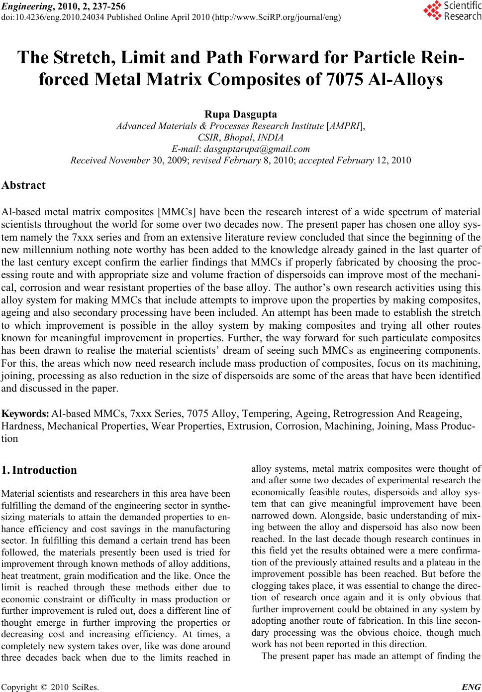 Engineering, 2010, 2, 237-256 doi:10.4236/eng.2010.24034 Published Online April 2010 (http://www.SciRP.org/journal/eng) Copyright © 2010 SciRes. ENG 237 The Stretch, Limit and Path Forward for Particle Rein- forced Metal Matrix Composites of 7075 Al-Alloys Rupa Dasgupta Advanced Ma terials & Processes Research Institute [AMPRI], CSIR, Bhopal, INDIA E-mail: dasguptarupa@gmail.com Received November 30, 2009; revised February 8, 2010; accepted Febr ua r y 12, 2010 Abstract Al-based metal matrix composites [MMCs] have been the research interest of a wide spectrum of material scientists throughout the world for some over two decades now. The present paper has chosen one alloy sys- tem namely the 7xxx series and from an extensive literature review concluded that since the beginning of the new millennium nothing note worthy has been added to the knowledge already gained in the last quarter of the last century except confirm the earlier findings that MMCs if properly fabricated by choosing the proc- essing route and with appropriate size and volume fraction of dispersoids can improve most of the mechani- cal, corrosion and wear resistant properties of the base alloy. The author’s own research activi ties using this alloy system for making MMCs that include attempts to improve upon the properties by making composites, ageing and also secondary processing have been included. An attempt has been made to establish the stretch to which improvement is possible in the alloy system by making composites and trying all other routes known for meaningful improvement in properties. Further, the way forward for such particulate composites has been drawn to realise the material scientists’ dream of seeing such MMCs as engineering components. For this, the areas which now need research include mass production of composites, focus on its machining, joining, processing as also reduction in the size of dispersoids are some of the areas that have been identified and discussed in the paper. Keywords: Al-based MMCs, 7xxx Series, 7075 Alloy, Tempering, Ageing, Retrogression And Reageing, Hardness, Mechanical Properties, Wear Properties, Extrusion, Corrosion, Machining, Joining, Mass Produc- tion 1. Introduction Material scientists and researchers in this area h ave been fulfilling the demand of the engineering sector in synthe- sizing materials to attain the demanded properties to en- hance efficiency and cost savings in the manufacturing sector. In fulfilling this demand a certain trend has been followed, the materials presently been used is tried for improvement through known methods of alloy additions, heat treatment, grain modification and the like. Once the limit is reached through these methods either due to economic constraint or difficulty in mass production or further improvement is ruled out, does a different line of thought emerge in further improving the properties or decreasing cost and increasing efficiency. At times, a completely new system takes over, like was done around three decades back when due to the limits reached in alloy systems, metal matrix composites were thought of and after some two decades of experimental research the economically feasible routes, dispersoids and alloy sys- tem that can give meaningful improvement have been narrowed down. Alongside, basic understanding of mix- ing between the alloy and dispersoid has also now been reached. In the last decade though research continues in this field yet the results obtained were a mere confirma- tion of the previously attain ed results an d a plateau in the improvement possible has been reached. But before the clogging takes place, it was essential to change the direc- tion of research once again and it is only obvious that further improve ment could be obtain ed in any system by adopting another route of fabrication. In this line secon- dary processing was the obvious choice, though much work has not been re p orted in this direction. The present paper has made an attempt of finding the 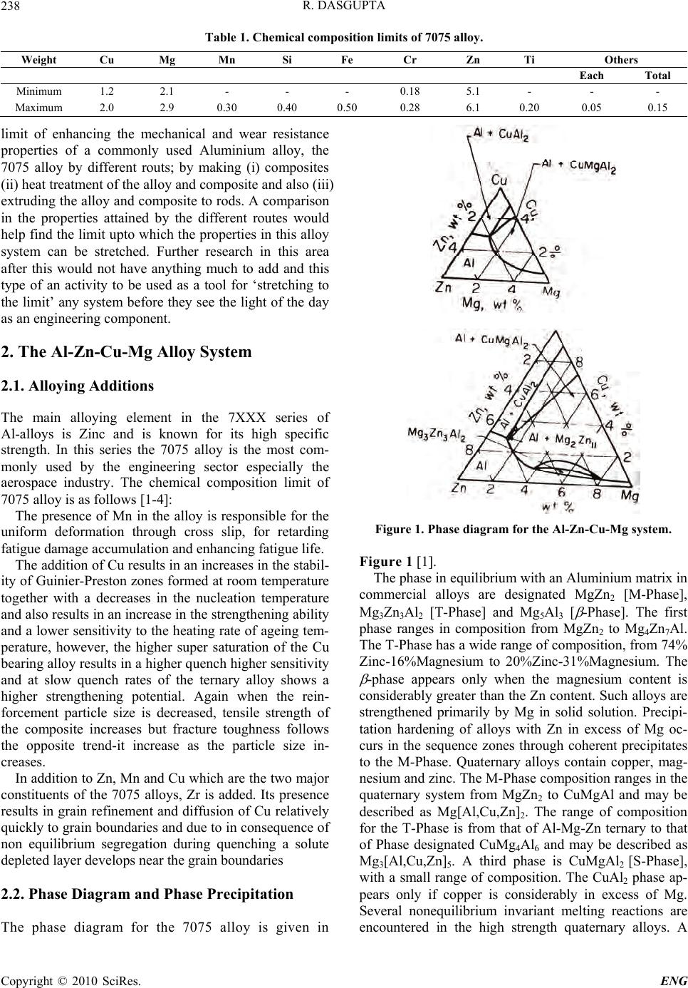 R. DASGUPTA 238 Table 1. Chemical composition limits of 7075 alloy. Weight Cu Mg Mn Si Fe Cr Zn Ti Others Each Total Minimum 1.2 2.1 - - - 0.18 5.1 - - - Maximum 2.0 2.9 0.30 0.40 0.50 0.28 6.1 0.20 0.05 0.15 limit of enhancing the mechanical and wear resistance properties of a commonly used Aluminium alloy, the 7075 alloy by different routs; by making (i) composites (ii) heat treatment of the alloy and composite and also (iii) extruding the alloy an d composite to rods. A comparison in the properties attained by the different routes would help find the limit up to which the properties in this alloy system can be stretched. Further research in this area after this would not have anything much to add and this type of an activity to be used as a tool for ‘stretching to the limit’ any system before they see the light of the day as an engineering component. 2. The Al-Zn-Cu-Mg Alloy System 2.1. Alloying Additions The main alloying element in the 7XXX series of Al-alloys is Zinc and is known for its high specific strength. In this series the 7075 alloy is the most com- monly used by the engineering sector especially the aerospace industry. The chemical composition limit of 7075 alloy is as follo ws [1-4]: The presence of Mn in the alloy is responsible for the uniform deformation through cross slip, for retarding fatigue damage accumulation and enhancing fatigue life. The addition of Cu resu lts in an increases in the stabil- ity of Guinier-Preston zones formed at room temperature together with a decreases in the nucleation temperature and also results in an increase in the strength ening ability and a lower sensitivity to th e heating rate of ageing tem- perature, however, the higher super saturation of the Cu bearing alloy results in a higher quench higher sen sitivity and at slow quench rates of the ternary alloy shows a higher strengthening potential. Again when the rein- forcement particle size is decreased, tensile strength of the composite increases but fracture toughness follows the opposite trend-it increase as the particle size in- creases. In addition to Zn, Mn and Cu which are the two majo r constituents of the 7075 alloys, Zr is added. Its presence results in grain refinement and diffusion of Cu relatively quickly to grain boundaries and due to in consequence of non equilibrium segregation during quenching a solute depleted layer develops near the grain bou nd a ri es 2.2. Phase Diagram and Phase Precipitation The phase diagram for the 7075 alloy is given in Figure 1. Phase diagram for the Al-Zn-Cu-Mg system. Figure 1 [1]. The phase in equilibrium with an Aluminium matrix in commercial alloys are designated MgZn2 [M-Phase], Mg3Zn3Al2 [T-Phase] and Mg5Al3 [ -Phase]. The first phase ranges in composition from MgZn2 to Mg4Zn7Al. The T-Phase has a wide range of composition, from 74% Zinc-16%Magnesium to 20%Zinc-31%Magnesium. The -phase appears only when the magnesium content is considerably greater than the Zn content. Such alloys ar e strengthened primarily by Mg in solid solution. Precipi- tation hardening of alloys with Zn in excess of Mg oc- curs in the sequence zones through coherent precipitates to the M-Phase. Quaternary alloys contain copper, mag- nesium and zinc. The M-Phase composition ranges in the quaternary system from MgZn2 to CuMgAl and may be described as Mg[Al,Cu,Zn]2. The range of composition for the T-Phase is from that of Al-Mg-Zn ternary to that of Phase designated CuMg4Al6 and may be described as Mg3[Al,Cu,Zn]5. A third phase is CuMgAl2 [S-Phase], with a small range of composition. The CuAl2 phase ap- pears only if copper is considerably in excess of Mg. Several nonequilibrium invariant melting reactions are encountered in the high strength quaternary alloys. A Copyright © 2010 SciRes. ENG 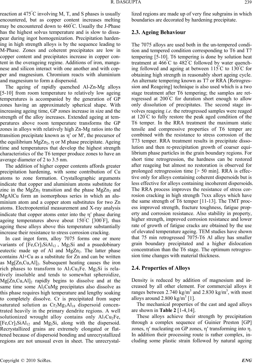 R. DASGUPTA 239 reaction at 475°C involving M, T, and S phases is usually encountered, but as copper content increases melting may be encountered down to 460°C. Usually the J-Phase has the highest solvus temperature and is slow to dissa- pear during ingot homogenization. Precipitation harden- ing in high strength alloys is by the sequence leading to M-Phase. Zones and coherent precipitates are low in copper content and precipitates increase in copper con- tent in the overageing regime. Additions of iron, manga- nese and silicon interact with one another and with cop- per and magnesium. Chromium reacts with aluminium and magnesium to form a dispersoid. The ageing of rapidly quenched Al-Zn-Mg alloys [5-10] from room temperature to relatively low ageing temperatures is accompanied by the generation of GP zones having an approximately spherical shape. With increasing ageing time, GP zones increase in size and the strength of the alloy increases. Extended ageing at tem- peratures above room temperature transforms the GP zones in alloys with relativ ely high Zn-Mg ratios in to the transition precipitate known as or M, the precursor of the equilibrium MgZn2, or M phase precipitate. Ageing time and temperatures that develop the highest strength characteristics of the T6 temper produce zones to have an average diameter of 2 to 3.5 nm. The addition of higher copper contents affords greater precipitation hardening, with some contribution of Cu atoms to zone formation. Crystallographic arguments indicate that copper and aluminium atoms substitute for zinc in the MgZn2 transition and the phase MgZn2 and MgAlCu form an isomorphous series in which an alu- minium atom and a copper atom substitutes for two Zn atoms. Electropotential measurement and X-ray analysis indicate that copper atoms enter into the phase during ageing temperatures above about 150°C [300°F], thus ageing these alloys above this temperature substantially increase their resistance to stress corrosion cracking. In cast ingot form, alloy 7075 forms one or more variants of [Fe,Cr]3SiAl12 , Mg2Si and a psuedobinary eutectic made up of Al and MgZn2. The latter phase contains Al+Cu as a substitute fo r Zn and can be written as Mg[Zn,Cu,Al]2. Subsequent heating causes the iron rich phases to transform to Al7Cu2Fe. Mg2Si is rela- tively insoluble and tends to somewhat spheroidize, Mg[Zn,Cu,Al]2 rapidly begins to dissolve and at the same time some Al2CuMg precipitates also dissolve as this phase r equires high temperatu re and leng thy soaking to completely dissolve. Cr is precipitated from super saturated solution as Cr2Mg3Al18 dispersoid concen- trated heavily in the primary dendrite regions. A well solutionized wrought alloy contains only Al7Cu2Fe, [Fe,Cr]3SiAl12 and Mg2Si, along with the dispersoid. Recrystallized grains are extremely elongated or flat- tened because of dispersoid bonding and unrecrystallized regions are not unusual even in sheet. The unrecrystal- lized regions are made up of very fine subgrains in which boundari es a re decorated by hardening precipi t a t e . 2.3. Ageing Behaviour The 7075 alloys are used both in the un-tempered condi- tion and tempered conditio n corresponding to T6 and T7 tempering [5-10]. T6 tempering is done by solution heat treatment at 466°C to 482°C followed by water quench- ing followed and ageing at between 115°C to 130°C for obtaining high strength in reasonably short ageing cycle. An alternate tempering known as T7 or RRA [Retrogres- sion and Reageing] technique is also used which is a two stage treatment after T6 tempering; the samples are ret- rogressed at 200°C for duration short enough to allow only dissolution of precipitates. The second stage in- volves reageing i.e. the retrogressed samples were reaged at 120°C to fully restore the peak aged condition of the T6 temper. In the RRA treatment the maximum static tensile and compressive properties of T6 temper are combined with the resistance to stress corrosion of the T73 temper. RRA treatment results in precipitate disso- lution and then re-precipitation growth of coarser equi- librium phase particles in the grain boundary regions. For short time retrogression, the hardness can be restored after reageing but almost no restoration is observed for prolonged retrogression time [> 50 min]. RRA is effec- tive only for alloys con taining co herent disperso ids but is less effective for alloys containing incoherent dispersoids. The RRA process improves the resistance of stress cor- rosion cracking in high strength 7xxx alloys which have the same strength of T6 temper [11-13]. The TMT proc- ess improved strength, fracture toughness, fatigue prop- erty and corrosion resistance. Also stability in property, higher strength, improv ed corrosion resistance and lower rate of growth of fatigue cracks are obtained by the use of elevated temperature ageing. TEM studies have shown that 75 min retrogressed 7075-T6 Al alloy has smaller grain boundary precipitated and a higher dislocation concentration than the T6 stage. The optimum retrogres- sion time changes with material thickness. 2.4. Properties of Alloys Density is reduced by addition of magnesium and in- creased by all other element. For commercial alloys it ranges between 2.740 kg/m3 and 2.830 kg/m3, with most alloys around 2.800 kg/m3 [1]. The mechanical properties of the cast and aged alloys are shown in Table 2 [1-4,14]. These alloys achieve their strength by precipitation through a complex sequence of Guinier Preston [GP] zones, nucleating on GP z o n es, transforming into . In addition their processing route is rather complex, in- cluding some plastic strain followed by natural ageing Copyright © 2010 SciRes. ENG 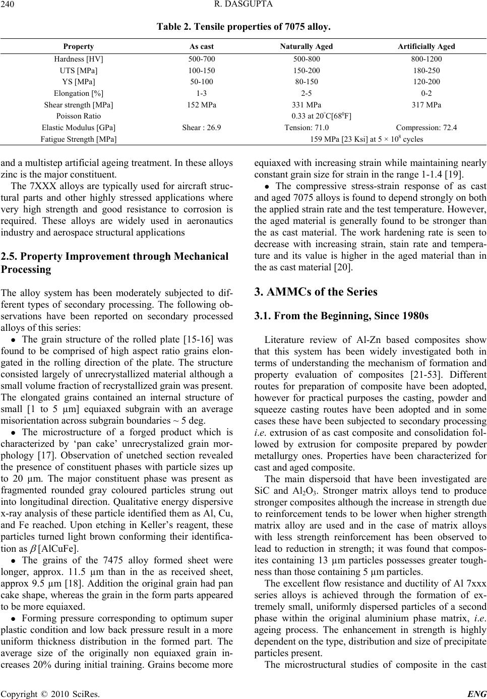 R. DASGUPTA 240 Table 2. Tensile properties of 7075 alloy. Property As cast Naturally Aged Artificially Aged Hardness [HV] 500-700 500-800 800-1200 UTS [MPa] 100-150 150-200 180-250 YS [MPa] 50-100 80-150 120-200 Elongation [%] 1-3 2-5 0-2 Shear strength [MPa] 152 MPa 331 MPa 317 MPa Poisson Ratio 0.33 at 20°C[680F] Elastic Modulus [GPa] Shear : 26.9 Tension: 71.0 Compression: 72.4 Fatigue Strength [MPa] 159 MPa [23 Ksi] at 5 × 10⁸ cycles and a multistep artificial ageing treatment. In these alloys zinc is the major constitu ent. The 7XXX alloys are typically used for aircraft struc- tural parts and other highly stressed applications where very high strength and good resistance to corrosion is required. These alloys are widely used in aeronautics industry and aerospace structural applications 2.5. Property Improvement through Mechanical Processing The alloy system has been moderately subjected to dif- ferent types of secondary processing. The following ob- servations have been reported on secondary processed alloys of this series: The grain structure of the rolled plate [15-16] was found to be comprised of high aspect ratio grains elon- gated in the rolling direction of the plate. The structure consisted largely of unrecrystallized material although a small volume fraction of recrystallized grain was present. The elongated grains contained an internal structure of small [1 to 5 µm] equiaxed subgrain with an average misorientation across subgrain boundaries ~ 5 deg. The microstructure of a forged product which is characterized by ‘pan cake’ unrecrystalized grain mor- phology [17]. Observation of unetched section revealed the presence of constituent phases with particle sizes up to 20 µm. The major constituent phase was present as fragmented rounded gray coloured particles strung out into longitudinal direction. Qualitative energy dispersive x-ray analysis of these particle identified them as Al, Cu, and Fe reached. Upon etching in Keller’s reagent, these particles turned light brown conforming their identifica- tion as [AlCuFe]. The grains of the 7475 alloy formed sheet were longer, approx. 11.5 µm than in the as received sheet, approx 9.5 µm [18]. Addition the original grain had pan cake shape, whereas the grain in the form parts appeared to be more equiaxed. Forming pressure corresponding to optimum super plastic condition and low back pressure result in a more uniform thickness distribution in the formed part. The average size of the originally non equiaxed grain in- creases 20% during initial training. Grains become more equiaxed with increasing strain while maintaining nearly constant grain size for strain in the range 1-1.4 [19]. The compressive stress-strain response of as cast and aged 70 75 allo ys is foun d to d ep end str on gly on bo th the applied strain rate and the test temperature. Howev er, the aged material is generally found to be stronger than the as cast material. The work hardening rate is seen to decrease with increasing strain, stain rate and tempera- ture and its value is higher in the aged material than in the as cast material [20]. 3. AMMCs of the Series 3.1. From the Beginning, Since 1980s Literature review of Al-Zn based composites show that this system has been widely investigated both in terms of understanding the mechanism of formation and property evaluation of composites [21-53]. Different routes for preparation of composite have been adopted, however for practical purposes the casting, powder and squeeze casting routes have been adopted and in some cases these have been subjected to secondary processing i.e. extrusion of as cast composite and consolidation fol- lowed by extrusion for composite prepared by powder metallurgy ones. Properties have been characterized for cast and aged composite. The main dispersoid that have been investigated are SiC and Al2O3. Stronger matrix alloys tend to produce stronger composites although th e increase in streng th due to reinforcement tends to be lower when higher strength matrix alloy are used and in the case of matrix alloys with less strength reinforcement has been observed to lead to reduction in strength; it was found that compos- ites containing 13 µm particles possesses greater tough- ness than those containing 5 µm particles. The excellent flow resistance and ductility of Al 7xxx series alloys is achieved through the formation of ex- tremely small, uniformly dispersed particles of a second phase within the original aluminium phase matrix, i.e. ageing process. The enhancement in strength is highly dependent on the type, distribution and size of precipitate particles present. The microstructural studies of composite in the cast Copyright © 2010 SciRes. ENG 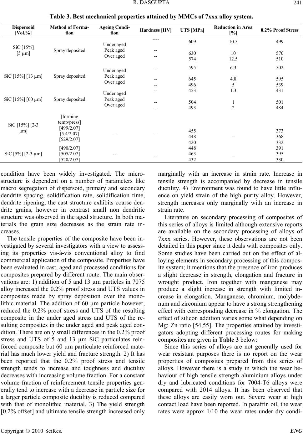 R. DASGUPTA 241 Table 3. Best mechanical properties attained by MMCs of 7xxx alloy system. Dispersoid [Vol.%] Method of Forma- tion Ageing Condi- tion Hardness [HV]UTS [MPa] Reduction in Area [%] 0.2% Proof Stress SiC [15%] [5 µm] Spray deposited Under aged Peak aged Over aged ---- -- -- 609 630 574 10.5 10 12.5 499 570 510 SiC [15%] [13 µm] Spray deposited Under aged Peak aged Over aged -- -- -- 595 645 496 6.3 4.8 5 502 595 539 SiC [15%] [60 µm] Spray deposited Under aged Peak aged Over aged -- -- -- 453 504 493 1.3 1 2 431 501 484 SiC [15%] [2-3 µm] [forming temp/press] [499/2.07] [5.4/2.07] [529/2.07] -- -- 455 448 420 -- 373 368 332 SiC [5%] [2-3 µm] [490/2.07] [505/2.07] [520/2.07] -- -- 448 463 432 -- 391 395 330 condition have been widely investigated. The micro- structure is dependent on a number of parameters like macro segregation of dispersoid, primary and secondary dendrite spacing, solidification rate, solidification time, dendrite ripening; the cast structure exhibits coarse den- drite grains, however in contrast small non dendritic structure was observed in the aged structure. In both ma- terials the grain size decreases as the strain rate in- creases. The tensile properties of the composite have been in- vestigated by several investigators with a view to assess- ing its properties vis-à-vis conventional alloy to find commercial application of the composite. Properties have been evaluated in cast, ag ed and processed cond itions for composites prepared by different route. The main obser- vations are: 1) addition of 5 and 13 µm particles in 7075 alloy increased the 0.2% proof stress and UTS values in composites made by spray deposition over the mono- lithic material. The addition of 60 µm particle however, reduced the 0.2% proof stress and UTS of the resulting composite in the under aged stress and UTS of the re- sulting composites in the under aged and peak aged con- dition. There are only small differences in the 0.2% proof stress and UTS of 5 and 13 µm SiC particulates rein- forced composite but 60 µm particulate reinforced mate- rial has much lower yield and fracture strength. 2) It has been reported that the 0.2% proof stress and tensile strength tends to increase and toughness and ductility decreases with increasing volume fraction. For a constant volume fraction of reinforcement tensile properties gen- erally tend to increase with a decrease in particle size for a larger particle composite ductility is reduced compared with that of monolithic material. 3) The yield strength [0.2% offset] and ultimate tensile strength increased only marginally with an increase in strain rate. Increase in tensile strength is accompanied by decrease in tensile ductility. 4) Environment was found to have little influ- ence on yield strain of the high purity alloy. However, strength increases only marginally with an increase in strain rate. Literature on secondary processing of composites of this series of alloys is limited although extensive reports are available on the secondary processing of alloys of 7xxx series. However, these observations are not been detailed in this p aper since it deals with compo sites only. Some studies have been carried out on the effect of al- loying elements in secondary processing of this compos- ite system; it mention s that the presence of iron pr oduces a slight decrease in strength, elongation and fracture in wrought product. Iron together with manganese may produce a slight increase in strength with limited in- crease in elongation. Manganese, chromium, molybde- num and zirconium appear to have a strong strengthening effect with corresponding decrease in % elongation. The effect of silicon addition varies some what depending on Mg: Zn ratio [54,55]. The properties attained by investi- gators adopting different processing routes for making composites are given in Table 3 below: Since this series of alloys are not generally used for wear resistant purposes there is no report on the wear properties of composites prepared from this series of alloys. However there is a study in which the wear be- haviour of high tensile strength aluminium alloys under dry and lubricated conditions for 7004-T6 alloys were compared with 2014 alloys. It has been observed that these alloys are easily worn out. Severe wear at high contact load have been reported. In paraffin oil, the wear rates were approx 1/10 the wear rates under dry condi- Copyright © 2010 SciRes. ENG  R. DASGUPTA 242 tions 7004-T6 showed a lower friction coefficient com- pared to 2024-T4. For 7004-T6, wear cracks which would propagate in the sliding direction occurred and large and elongated particles were detected [48-53]. Creep re sistance of the alloys and composites both are relatively low, however longer creep life can be achieved if the load is intermittently relieved and the material is allowed a period of rest. Residual stresses from working processes may reduce creep resistance and so does pre- cipitation during creep [56-58]. 3.2. The Recent Past [Since 2000] The recent past has not since much progress in the re- search of this series of composites. The researchers have more or less confirmed the findings of earlier researchers and at times provided an understanding of the behaviour observed. The role of work hardening characteristics of matrix alloys in the strengthening of metal matrix com- posites has been shown to be associated with a high dis- location density in the matrix due to the difference in coefficient of thermal expansion between the reinforce- ment and the matrix. In a study where the composites were made by a pressureless infiltration method, the composite reinforced with SiC particles exhibited higher strength values than the control alloy in all aging condi- tions (underaged (UA), peak-aged (PA), and overaged (OA)), as well as a solution treated condition. Spontane- ous infiltration was further prompted owing to the com- bined effect of both Mg and Zn. This may lead to an en- hancement of wetting between the molten alloy and the reinforcement. Consequently, strength improvement in a composite may be attributed to good bond strength via enhancement of wetting. The grain size of the control alloy is greatly decreased to about 2.5 mm compared to 10 mm for the commercial alloy. In addition, the grain size in the composite is further decreased to about 2mm. These grain refinements contributed to strengthening of the control alloy and the composite [59]. In another re- cent study, the role of work hardening characteri stics has been shown to be due to increased prismatic punching of dislocations. This relationship of decreasing work hard- ening rate associated with increasing prismatic punching of dislocations for different Al-based matrices is in the order 7075, 2014, 7010, 2024, 6061 and commercial purity aluminium leading to increased strength incre- ments has been noted. From the study, it is concluded that lower the work hardening rate, higher is the strengthening and vice versa in particulate metal–ma- trix composites [60]. The corrosion behaviour of the MMCs was studied by electrochemical measurements to study the effect of the addition of silicon carbide on the corrosion behaviour of the MMC [61]. The electro- chemical noise result shows that the amplitude of the potential noise of the composite is lower than that of the spray deposited 7075 alloy. The potentiodynamic polari- zation curves results show that both the cathodic oxygen reduction current density and the anodic dissolution cur- rent density of the 7075/SiCp MMC are less than those of the 7075 alloy. Thus, the addition of SiC particles increases the corrosion resistance of the MMC. This may be due to that the microstructure of the spray deposited MMC is compact and SiC particles are nonmetallic ma- terial, the addition of it minimizes the real corrosion area of the alloy. In another study [62], an attempt has been made to fabricate Al-SiCp and Al-Al2O3 compos ite mate- rials by powder metallurgy technique at different volume percentage of reinforcement (5, 10, 15, 20, and 25%). The corrosion behavior of the composites was analyzed using AC Gill potentiostat with 3.5 wt% NaCl medium. Four factors, five level, central composite, rotatable de- sign matrix is used to optimize the required number of experiments. The mathematical models were developed by the response surface method (RSM). The developed models have been checked for their adequacy and sig- nificance by the F-test and t-test, respectively. The re- sults obtained from the mathematical models have been optimized and also tested using conformity test runs that closely match the experimental results. A mathematical model has been successfully developed [63] to predict the wear rate of AA7075 aluminium/SiCp composite material fabricated by powder metallurgy technique at 95% confid en ce leve l with in rang e of inv estig atio n b ased on the results obtained after studying the effect of rein- forcement particle size, applied load and slid ing sp eed on the dry sliding wear behaviour of AA7075 alumin- ium/SiCp composites fabricated by powder metallurgy technique with 5–2 5 vol.% SiCp with an average particle size of about 40–150µm using the conventional powder metallurgy (P/M) process. The effect of selected process variables on the porosity of 7075 Al alloy 10% SiC composite and subsequent optimal settings of the vari- ables have been obtained using Taguchi method [64]. The results indicate that the holding time, holding tem- perature and stirring speed are the significant variables. Stirring time is insignificant variable. As the holding time, holding temperature and stirring time increases the porosity decreases. When the stirring speed increases, porosity increases. The pr edicted optimal valu e of poros- ity is 4.71%. Although very limited studies have been reported on processing of composites, a particular study reports in detail the effect of extrusion and rolling on a SiCp/7075 aluminum alloy composite fabricated by squeeze casting using a vortex method [65]. The composites were hot rolled to the total rolling reduction of about 94% at tem- peratures between 573 K and 773 K and at a rolling strain per pass of 0.10. Superplastic characteristics such as microstructure and apparent activation energy were compared with these of the composites made by other processes in order to clarify the sup erplastic deformation mechanism. Fine grain size of about 1 μm was attained Copyright © 2010 SciRes. ENG  R. DASGUPTA 243 in the composite rolled at a temperature of 573 K and at the strain per pass of 0.1. In the case of rolling at 573 K, the composite obtained exhibited high strain rate super- plasticity with a maximum elongation of about 230% at strain rate of 7 × 10⁻¹ s 1 and at 798 K. Plots between ε1 and σ showed linear relation when exponent of n = 2 was assumed. Threshold stresses obtained from the linear relations were largely dependent on the testing tempera- ture. Apparent activation energy determined from rela- tionship between strain rate and testing temperatures was 244 kJ/mol, which was smaller than that for the pow- der metallurgical and mechanically alloyed Alumin- ium composite. It seems that there is no substantial dif- ference of high strain rate superplastic mechanism be- tween the composite fabricated by a vortex method and powder metallurgical aluminum alloy composites. 3.3. What Has Seldom Been Tried Inspite of the enormous amount of R&D that has gone into Al-based MMCs of every possible alloy with dif- ferent dispersoids establishing beyond doubt the useful- ness of making composites that can be competitive on a production scale to Al-alloys and steels in some cases, and although some of these have already been in com- mercial use now, a few areas still remained to be ex- plored. These areas have seldom been researched on or reported in the literature though all researchers would agree that these areas needs to be addressed to before Al-base composites are freely available in the market as an alternative to commercial alloys for engineering ap- plications. The areas in which very little or no work has been done/reported include the following: Machining of Composites: Particulate MMCs are invariably harder than the base alloy and more abrasive due to the incorporation of the second phase. Hence ma- chining of these poses difficulty as tools used for Al-based alloys are generally used even for the MMCs; the tools wear out fast and needs frequent replacement that adds to the cost of processing of these materials. Most of the times when conventional tools used for Al do not work properly or are blunted tools for machining harder materials like diamond tip tools are used which are costly. But a systematic study has not been done in trying to fabricate/design tools especially for MMCs. Joining of Composites: This aspect has not at all been reported though it is a very important area as mak- ing components will require joining of two pieces quite frequently. Welding could be the most apt method of joining but welding rods for the purpose needs to be de- veloped. The other kn own methods of joinin g similar and dissimilar metals needs to be assessed and researched on. Primary/Secondary Processing: The literature avail- able on primary processing including forging, extrusion and rolling is very limited and scanty. Most of the work is on extrusion of only MMCs made from powder met- allurgy route in which small samples have been extruded. But before thinking of engineering applications for MMCs, the difficulties in processing these materials needs to be addressed to and parameters optimised. The present paper reports some of the authors’ experience in this field. Equi Channel Angular Pressing: Equi Channel An- gular Pressing [ECAP] is emerging as a competitive route of processing Al-based alloys wherein the grain size is drastically decreased by passing billets through a die containing two channels, equal in cross section, in- tersecting at a certain angle introducing large shear strain without any reduc tion in the cr oss section of th e material. Since the process is applicable to large samples, it ap- pears to have the potential for significantly changing the material properties by effective grain size reduction even in a bulk form. This area has never been reported to have been tried for MMCs. It is felt that Al-based MMCs will respond positively to ECAP adding to the benefits of composite making. Ultrafine Dispersoids: Dispersoid size, shape, vol- ume fraction, wettability and distribution play the most important role in the properties attained in MMCs. A lot of research has centered on optimizing these parameters and based on the results property designing of compos- ites is possible. However, all the experimentation has stopped at decreasing the dispersoid level below 10µm, possibly due to the d ifficulty in dispersing uniformly and without coagulation finer particles in the matrix espe- cially when the liquid metallurgy route is adopted for making the composites. If the coagulation problem can- not be addressed on decreasing the particle size below 10 µm, alternate methods of fabrication have to be at- tempted at like in-situ composites, which has been a modern trend of research for making MMCs. Again, in the present age of nano materials methods of dispersion or making composites with nano sized dispersoids holds a lot of potential for commercial exploitation in the fu- ture. Bulk Production: One of the causes could be the most important cause as to why Al-based MMCs inspite of all its advantages are yet to see the light of the day extensively as engineering components is the level of production . Researchers are content with the h igh quality yet small quantities that they can repetitively produce in their laboratories, but the engineering sector is not con- vinced that the same benefits can be replicated on up scaling. Either party is not ready to bridge the gap by producing the material in bulk due to a number of rea- sons different for either party. But unless the fear in the mind of the users is removed as to the property im- provement even when produced in bulk quantity by the researchers, their dream to see their research product in the market will be difficult to realise. So also, the manu- facturing units should be entrepreneurial enough to take some risk in this matter, as certain changes might be Copyright © 2010 SciRes. ENG  R. DASGUPTA 244 needed in their production line up when alloys are re- placed by composites. Somewhere by some groups are needed to take up the challenge of bridging the gap if Al-MMCs are to see the light of the day in the near fu- ture. 4. Our Results The present paper has made an attempt of finding the limit of enhancing the mechanical and wear resistance properties of a commonly used Aluminium alloy, the 7075 alloy by different routs; by making 1) composites 2) heat treatment of the alloy and composite and also 3) extruding the alloy an d composite to rods. A comparison in the properties attained by the different routes would help find the limit up to which the properties in this alloy system can be stretched. The experimental setups and results obtained are detailed below. 4.1. Experimental Details 4.1.1. Making of Allo y and Composite The Al-based alloy confirming to the 7075 composition with 1.6 Cu, 2.5 Mg, 5.6 Zn, 0.3 Cr was selected for the present study. The chemical composition of the alloy was analysed using SPARKMET optical spectrometer [Model: SPECTRA] for confirmation . For preparing composites from these alloys; 10 vol- ume % of dispersoids of SiC of were used with size be- tween 20-40 m. The composites were prepared by the liquid metallurgy technique. For preparing the compos- ites, the alloys were melted in a gas fired furnace in a graphite crucible. The melted alloy was fluxed with Coveral 11 and degassed with dry nitrogen gas. The pre weighed quantity and preheated dispersoids were poured into the melt after passing through a sieve. During inser- tion of the dispersoid the melt was stirred constantly by means of a stirrer placed in the melt operated by a motor. The stirrer speed was controlled as required. After com- plete insertion of the dispersoids in the molten alloy, the alloy was simultaneously stirred and heated for some time for uniform mixing and temperature. The melt with the dispersoids were then poured into preheated perma- nent moulds of required size and shape. 4.1.2. Ageing and Tempering The alloys and composites were aged under T6 temper- ing and adopting retrogression and re-ageing method [RRA]. In the RRA method, the samples were quenched and aged as per the fo llowing ste ps: The alloys and composites were aged at 490°C for 8 hours and water quenched. The quenched samples were heat treated at 120°C for 24 hours and were furnace cooled. This corresponds to T6 ageing. The T6 aged samples were retrogressed at 200°C for 45 minutes. The retrogressed samples were re-aged at 120°C for 24 hours. 4.1.3. Extrusion A 400 tonne hydraulic press with extrusion facility was used for extrusion experimentation. The alloy and com- posites were sized to a diameter of 50mm diameter and ~ 60mm length for extrusion to rods at an extrusion ratio of 10:1. The billets were homogenised under at 480ºC for 12 hours. A pressing speed of 0.4mm/sec was used and billets were soaked at 350ºC for two hours before extru- sion. The container, liner and billet were maintained at the extrusion temperature by externally heating the com- plete setup, to prevent heat loss during extrusion. The pressure required for successful extrusion was compared for optimizing the extrusion process. 4.1.4. Laboratory Tests For microstructural studies, samples from the cast and aged alloys and composites of size approximately 20 mm diameters were metallographically polished and etched in Kellar’s reagent. The microstructure of the sample was observed in the optical microscope at lower magnifica- tions upto X500 and in the JEOL scanning electron mi- croscope operating at 20KV at higher magnifications for a better understanding of the constituent phases in the microstructures. The secondary mode of electron emis- sion was initially used for the microstructural investiga- tions. However, when the precipitates expected to be precipitated at the grain boundaries was not properly visible with this mode, the back scattered electron emis- sion mode of the scanning electron microscope was used for observi n g t he precipitation of phases. Bulk hardness was determined using the EQUOTIP SN 716-1159, Vers-1.16 hardness tester in which the indentation was produced using the Tungsten carbide ball indenter of 20mm diameter with a test tip of 3mm diameter. The tensile properties i.e. ultimate tensile strength [UTS] and % elongation were determined in the Shima- dzu make Universal Testing Machine [UTM] of capacity 100 tonne. Tests were carried out at a load of 4 tonne with load increment of 0.4 tonne. Fractographic analysis of the fractured tensile samples was carried out in which the fractured surface was observed in the scanning elec- tron microscope in ord er to understand the mechanism of material failure and changes in the mode of failure, if an y, as a result of adding particulates to the alloy and extrud- ing them. The specimens were subjected to dry sliding wear tests under dry conditions using a pin-on-disc wear testing [Figure] [Cameron Plint make]. The test specimen in this case were in the form of cylindrical pins of length 53mm and 8mm in diameter and the disc counterpart was of AISI 304 grade stainless steel [Fe 0.08-C 2.0-Mn 1.0- Si 8.0-Ni 18.0 Cr] having a hardness of 194 HV. The specimen was held against the rotating steel disc and this Copyright © 2010 SciRes. ENG  R. DASGUPTA Copyright © 2010 SciRes. ENG 245 sliding motion results in wear of the pin. The weight of the specimen was taken after every 500 m, sliding dis- tance. The weight loss was calculated from the difference in weight between the initial weight and weight after a specified number of rotations. Dividing the weight loss by the density of the material [calculated by Archimedes principle] gives the volume loss. This volume loss was taken for comparing the wear behaviour. Further, the wear rate was calculated by dividing the volume loss by the total distance traversed. Experiments were conducted in the present stud y at two speeds of rotation, one low at 200 rpm and the other high at 750 rpm corresponding to linear speeds of 1.04 m/s and 3.92 m/s respectively. Tests were carried out under three applied pressures, i.e. 1, 3 and 5 MPa; wear loss was measured at distance cor- responding to a sliding distance of 2500 m at intervals of 500 m and the corresponding volume loss calculated. Temperature rise of the specimen was not noted under the present study. The worn surface was studied under the scanning electron microscope [SEM] to study the nature of material removal and surface damage and to compare between material removal mechanism between the cast, aged and extruded conditions and between the alloy and composites under identical conditions. 4.2. Results and Discussion 4.2.1. Microstructural Observations The microstructure of the cast, aged under T6 and RRA conditions and extrud ed rods for the alloy and compo site is shown in Figure 2. In the as cast state, the 7075 alloy shows heterogene- ous precipitation along the grain boundaries as well as inside the grain boundaries [Figure 2(a)]. The alloy ex- hibits a black filigree of Mg Zn [18]. Und er T6 con dition s , there is heavy precipitation in the grains although the grain boundaries are not very clearly defined [Figure 2(b)], and under RRA conditions dissolution of grain boundaries was observed [Figure 2(c)] and shows a granular structure with grains of varying size and distri- bution of very fine phases in the grains in the Al-matrix resulting from non uniform solidification rates during casting [Figure 2(a)]. On extrusion directionality is seen along the longitudinal direction and the grain structure is completely broken down [Figure 2(d)]. The transverse section exhibits a granular structure [Figure 2(e)] but the phases are not much resolved. The cast composite exhib- its [Figure 2(f)] a near uniform distribution of the par- ticulates within the matrix and clear dendrites are seen in the matrix of Aluminium; grain boundaries are clearly defined with some precipitates in the grains. On age- ing the 7075 composite, dissolution of grain bounda- ries was observed together with coagulation of pre- cipitates around the SiC dispersoids [Figure 2(g)]. Again on extrusion directionality [Figure 2(h)] is seen and distribution of particulates uniformly is also ob- served. In the transverse section of the extruded compos- ite, studs of the particle heads can be seen uniformly dis- tributed in th e matrix [Figure 2(i)]. A few particles [dis- persoids] are seen to have been conglomerated in the extruded condition. 4.2.2. Hardness The bulk hardness [HB] was measured on at least ten locations on the polished and etched sample and the av- erage of the values with standard deviation are tabulated in Table 4. It is seen from the above table that making composites drastically increases the hardness of the alloy by nearly 40% and extruding them further increases the value by some 25% [Table 2]; the latter improvement is due to strain induced strengthening during the processes in- volved. 4.2.3. Tensile Properties and Fractographic Studies The stress-strain graph for the extruded alloy and com- posite is shown in Figure 3(a) and (b) respectively. From the nature of the graph it is seen that the alloy exhibits a ductile behaviour but the composite shows a brittle failure. This is possibly due to the incorpor ation of the SiC particles that are uniformly distributed in the matrix giving the composite a brittle nature. The fracto- graphic studies of the alloy and composite in the cast condition [Figure 4(a) and 4(b) respectively] confirm the loss of ductility on forming composites as the former shows cup and cone type of fracture relating to ductile nature and the latter shows cleavage facets, voids with inclusions [marked by *] and micro cracks [marked by ar- row] which are characteristic features of brittle nature of failure. The deep voids with inclusions are the possible cause of fract ure in t his case . The Ultimate Tensile strength [UTS] of the cast, ho- mogenised and extruded alloys and composites are shown in Table 5 and plotted in Figure 5 for comparison. It is seen that homogenisation increases the UTS for both the alloy and composite resulting possibly from uniformity in the distribution of phases. Extrusion further improves the UTS in the case of alloy though marginally; however for com- posites a slight decrease has been recorded. The reported results are an average of three sam ples tested in each case. The fractographs of the tested samples reveals the nature of failure and the effect of homogenisation and/or ex trusion on the nature of the sample if any. The fractograph of the homogenised alloy [Figure 6(a)] is very similar to the cast alloy [Figure 6(a)] exhibiting uniform dim- Table 4. Hardness of alloy and composite under dif- ferent conditions. System As Cast RRA Extruded Alloy .22 7+ .0650 3+.071 3+.696 Composite .35 8+ .679 3+.172 4+.2101  R. DASGUPTA 246 a: Cast Alloy b: Aged Alloy –T6 c: Aged Alloy - RRA d: Extruded Alloy- longitudinal d irection e: Extruded Alloy- transverse direction f: Cast Composite g: Aged Composite –T6 h: Extruded Composite-longitudi nal direction i: Extruded Com posite- tra ns v er s e directio n Figure 2. Microstruct ur e under different conditions. 0 20 40 60 80 100 120 140 160 180 0 2 46 810121416 Strain Stress, MPa -20 0 20 40 60 80 100 120 140 -0.0500.05 0.10.15 0.20.25 0.3 Strain Stress, MPa Figure 3. (a) Stress-Strain gr aph for e x tr ude d alloy; (b) Stress-Strain graph for extruded composite. ples [marked A], with tear r idges indicative of cup and cone type of fracture [marked B] and large number of voids [marked C] indicating ductile fracture [66]. The smooth and fibrous region with proper neck formation at lower magnifications [Figure 6(b) & (c)] confirms a pure ductile mode of fracture in both the homogenised and extruded samples. The broken surface of the extruded alloy also exhibit similar structure [Figure 6(d)] with a Copyright © 2010 SciRes. ENG  R. DASGUPTA 247 Table 5. UTS of Samples. Sample UTS, MPa Cast Alloy 87.57 + 5.23 Homogenised alloy 159.09 + 1.88 Extruded alloy 165.59 + 2.08 Cast Composite 81.85 + 6.77 Homogenised Composite 112.08 + 1.48 Extruded Compo s it e 103.10 + 3.15 (a) (b) Figure 4. Fractured surface (a) ductile failure for alloy (b) brittle failure of composites. high density of equiaxed dimples that is found mainly in ductile materials. Fracture by micro void coalescence [6 7] is the only mode of fracture to be confirmed. No other physical parameter can be seen in the fractographs of the alloys. In the case of composites, the fractured surface exhib- its a slight modification on homogenisation in which voids are seen along with the cleavage in a very scattered manner [Figure 7(a)] unlike the cast condition where only cleavage facets indicative of brittleness is observed [Figure 7(b)]. The river patterns on the facets can also be seen [Figure 7(b)] a clear indication of the brittle mode of the fracture in the homogenised samples [68]. Extrusion however increases the number of voids in the fractographs to a considerable extent; certain portions reveal a smoother surface of fracture, revealing numer- ous equiaxed dimples, suggestive of ductile tensile frac- ture [Figure 7(c)]; at times incomplete material removal processes are also seen [marked by arrow]. Higher mag- nification fractographs [Figure 7(d)] shows dimples with an inclusion, which could have been the cause of fracture along with some stretched cleavage facets and majority of shallow dimples. This indicates a mixed mode of fracture i.e. ductile and brittle fracture in the extruded composites. 4.2.4. Slidi ng Wear Behaviour and Worn Surf ace Studies Sliding wear tests were carried out on the cast, homoge- nised and extruded alloy and composite under two speeds of rotation 200 and 750rpm and under three pres- sures corresponding to 1, 3 and 5 MPa and the volume loss against sliding distance plo tted. It was found that the alloy in all the conditions seized at 5 MPa pressure at both the speeds of rotation, whereas composites sus- tained the pressure at the lower speed of rotation. Again, alloys seized even at 3MPa pressure at the higher speed of rotation whereas the composites could sustain the conditions upto the sliding distance tested i.e. 2500 m. Seizure of the material can be understood from the ma- chine stopping and also from the surface being tested which shows material movement; the scanning electron micrographs of seized samples [Figure 8] shows com- plete overlapping of material and material movement cutting across wear tracks [Figure 8(a)]; the seized ma- terial in turn do not show any structure and looks like a lump of mass on the surface adhered to the surface and material from the inner surface ar e also exposed [Figure 8(b)]. In order to compare the behaviour between the alloy and composite for a particular experimental condition, the volume loss against sliding distance is plotted as in Figure 9, shown below. It is seen that under all the experimental conditions, the composite exhibits lesser volume loss as compared to the alloy through the duration of the test. Moreover, homogenisation of alloy or composite doesnot have any significant bearing in reducing the volume loss and this is probably due to softening of the matrix as a result o f homogenisation and volume loss is directly dependant on the hardness and stiffness of the material. The volume loss for composites is significantly lower than the alloy under a particular experimental condition, especially under the same sample condition. Extrusion has a significant effect in decreasing the volume loss for both alloy and compositeand under a pressure of 3 MPa and 200 rpm, Copyright © 2010 SciRes. ENG  R. DASGUPTA 248 UTS, MPa 87.57 159.09 165.59 81.85 112.08 103.1 0 20 40 60 80 100 120 140 160 180 C ast Alloy Homogenised alloy Extruded alloy Cast Composite Homogenised Composite Extruded Composite Figure 5. Comparative plot of UTS of the samples. (a) )b( (c) (d) Figure 6. Fractographs of alloys under different conditions. (a) Homogenised alloy; (b) neck formation at lower magnifica- ions for homogenised and extruded alloy s; (d) e x tr ude d alloy. t the extruded alloy even exhibits less volume loss i.e. better wear resistance than the cast and homogenised composite. It is interesting to note that higher speeds of rotation results in lesser volume loss which is probably Copyright © 2010 SciRes. ENG  R. DASGUPTA 249 (a) )b( (c) (d) Figure 7. Fractographs of composites under different conditions.(a) Homogenised composite; (b) homogenised composite showing river patterns on the cleavage facets; (c) extruded composite showing incomplete material removal processes marked by arrow; (d) magnified view of ‘c’ showing stretched cleavage facets and shallow dimples. (a) )b( Figure 8. Micrographs of seized samples. due to less time that the surfaces get to slid e against each other due to the enhanced speed; the material damage is also less in such cases as seen from comparing its worn surfaces at a particular load at different speeds [Figure10]. The effect of load on volume loss is more p redomin ant in the cast condition that in the extru d ed conditio n as can be seen on comparing Figures 9(a) and (b). Unlike alloys, which have seized even under a pres- sure of 3 MPa at higher speeds of rotation, composites have not experienced seizure under a pressure of 3 MPa Copyright © 2010 SciRes. ENG  R. DASGUPTA 250 0 0.1 0.2 0.3 0.4 05001000 1500 2000 2500 3000 Sli ding Distan ce , m Volume Loss, mm3 Alloy CastAlloy Homogenised Alloy Ext rudedComposite Cast Composite HomogenisedComposite Extruded 1 MPa, 200 rpm 0 0.01 0.02 0.03 0.04 0.05 0.06 0.07 05001000 1500 20002500 3000 Sliding Dist ance, m Volume Loss, mm3 Alloy CastAlloy Homogenised Alloy ExtrudedCo mpo s i te Cast Composite HomogenisedCom po site Extruded 1 MPa, 750 rpm 0 0.1 0.2 0.3 0.4 05001000 1500 20002500 3000 Sli ding Distance, m Volume Loss, mm3 Alloy CastAlloy Homogenised Alloy Ext rudedCompos i te Ca st Composite HomogenisedComposite E xtr uded 3MPa, 200 rpm Figure 9. Comparison of volume loss with sliding distance between alloy and composite under different conditions. under any condition; however the cast and homogenised composites have seized after traversing a minimal dis- tance when the pressure was increased to 5MPa, but even in this condition at both the speeds of rotation they could complete the duration of the test in the extruded condi- tion without any signs of seizure on its worn surface [Figure 11]. The advantage of making composites even Figure10. Worn surface showing effect of speed at a pressure of 1 MPa. (a)alloy at 200 rpm; (b) alloy at 750 rpm; (c) composite at 200 rpm; (d) composite at 750 rpm. Copyright © 2010 SciRes. ENG  R. DASGUPTA Copyright © 2010 SciRes. ENG 251 In order to compare the effect of extrusion on wear behaviour of composites, the variation for composites under experimental conditions where alloys have seized is plotted in Figure 12. In the Figure, the nature of lines represents the pressure applied like dashed lines repre- sents a pressure of 3 MPa and a filled line a pr essure of 5 MPa; again filled symbols represents a sliding speed of 200 rpm and unfilled symbols a speed of rotation of 700 rpm; likewise the letters A, D and G is the cast, B, E and H the homogenised and C, F and I the extruded con- ditions. From the graph it is seen th at the (i) under condi- tions where the cast and homogenised composites seize at 5 MPa pr essure when th e speed of rotation is 750 rpm but the extruded composites do not seize (ii) homogeni- sation or heat treatment softens the material leading to more volume loss under the same experimental condi- tions even over the cast condition (iii) extruded compos- ites exhibits better wear resistance [as measured from inverse of volume loss] than the cast condition at high pressures; however at lower pressures the cast condition performs marginally better or it can be said that there is no beneficial effect of extrusion when the load is com- paratively less, that is to say that extrusion makes the composites more versatile to withstand harsher condi- tions of wear re l at e d dam a ge. 5. Achievements in a Nutshell Al-Zn based composites prepared through different routes like casting, powder and squeeze casting routes have been extensively reported and have been exten- sively been characterised on a laboratory scale and in very rare cases have these been subjected to secondary processing. However any engineering component from the composites has still no t been reported. The main dis- persoid that have been investigated are SiC and Al2O3. The main findings and best results obtained as a result of forming MMCs are as follows: Stronger matrix alloys tend to produce stronger composites although the increase in strength due to rein- forcement tends to be lower when higher strength matrix alloy; it was found that composites containing 13 µm particles possesses greater toughness than those contain- ing 5 µm particles. The microstructural studies of composite in the cast condition is dependent on a number of parameters like macro segregation of dispersoid, primary and secondary dendrite spacing, solidification rate, solidification time, dendrite ripening; the cast structure exhibits coarse den- drite grains, however in contrast small non dendritic structure was observed in the aged structure. In both ma- terials the grain size decreases as the strain rate in- creases. Figure 11. Worn surface of composites at 5MPa pressure. (a) Cast at 200 rpm; (b) Extruded at 200 rpm; (c) Extruded at 750 rpm. from a non conventional wear resistant alloy like the one being discussed is thus established from the above stud- ies and it brings home the point that extrusion improves the sliding wear resistance properties in both the alloy and composite. The tensile properties of the composite have been investigated by several investigators with a view to as- sessing its properties vis-à-vis conventional alloy to find  R. DASGUPTA 252 0 0.05 0.1 0.15 0.2 0.25 05001000 15002000 2500 3000 3500 Sliding Distance, m Volume Loss, m m3 A B C D EF G HI A: Cast, 3MPa, 750 rpm; B: Homogenised, 3MPa, 750 rpm; C: Extruded, 3MPa, 750 r pm D: Cast, 5MPa, 200 rpm; E: Homogenised, 5MPa, 200 rpm; F: Extruded, 5MPa, 200 rpm G: Cast, 5MPa, 750 rpm; H: Homogenised, 5MPa, 750 rpm; I: Extruded, 5MPa, 750 rpm Figure 12. Comparison of wear behaviour under different conditions for composites. commercial application of the composite. It was found that the properties are dependant on several factors like particle size and volume fraction and there is a peak in the properties attained limiting the size and volume of dispersoids possible for better properties over the mono- lithic material. The best mechanical properties attained in MMCs of this class are made through powder metallurgy routes though this route is not practical for large components and is not economical. Strength improvement in a composite may be at- tributed to good bond strength via enhancement of wet- ting; also presence of the combination of Mg and Zn helps in wetting in this alloy system. This again is de- pendant on the forming technique and spontaneous infil- tration has been found to give the best properties due to an enhancement of wetting between the molten alloy and the reinforcement. Effect of alloying elements has an effect even on the properties even after secondary processing of this composite system; the presence of iron produces a slight decrease in strength, elongation and fracture in wrought product. Iron together with manganese may produce a slight increase in strength with limited increase in elon- gation. Manganese, chromium, molybdenum and zirco- nium appear to have a strong strengthening effect with corresponding decrease in % elongation. The effect of silicon addition varies some what depending on Mg: Zn ratio. It has been observed that these alloys are easily worn out. Severe wear at high con tact lo ad have been reported. In paraffin o il, the wear ra tes were approx 1/10 the w ear rates under dry conditions; however 7004-T6 showed a lower friction coefficient compared to 2024-T4. Creep resistance of the alloys is relatively low, es- pecially for high strength alloys. However, such studies have not been reported for composites of these alloys. The role of work hardening characteristics has been shown to be associated with a high dislocation density in the matrix due to the difference in coefficient of thermal expansion between the reinforcement and the matrix. The corrosion behaviour of the MMCs was studied by electrochemical measurements to study the effect of the addition of silicon carbide on th e corrosion behaviour of the MMC. The corrosion behaviour of the metal ma- trix composite show that both the cathodic oxygen re- duction current density and the anodic dissolution current density are less than those of the allo y. Thus , th e addition of SiC particles increases the corrosion resistance of the MMC. Very limited studies have been reported on proc- essing of composites. In a study, the composites were hot rolled to the total rolling reduction of about 94% at tem- peratures between 573 K and 773 K and at a rolling strain per pass of 0.10. Inspite of the enormous amount of R&D that has Copyright © 2010 SciRes. ENG  R. DASGUPTA 253 gone into Al-based MMCs of this alloy establishing be- yond doubt the usefulness of making composites they are yet to produced at competitive rates on a production scale. Until this is done the possibility of making com- ponents from the composites inspite of all its advantages will remain a dream. Again, before components are thought of some ar- eas needs address. Till now conventional methods/tools as used for the alloys have been used for the purpose but further development and exclusive research on compos- ites per se needs to be addressed to. These include: Machining of C omposites Joining of Composites Primary/Se condary Pr o cessi n g Equi Channel An g ul a r Pressing Composites from Ultrafine Dispersoids 6. The Stretch, Limit and The Future The contributions made towards increasing the state of knowledge in enhancing the physical, mechanical, wear and corrosion resistance has established the efficacy of making composites with better properties than the alloy; the conditions under which the improvements can be best realised have also been established by different research- ers throughout the world mainly th rough laboratory scale studies. It is seen that the properties attained has been stretched to the maximum possible and there is no much scope of further improvement in the properties as the methods and materials used have all been optimised; and since the last decade no further improvement in terms of properties have been recorded. This in a way has put a limiting factor for further improvem ent. The next step would be to mass produce these com- posites adopting the techniques and adhering to parame- ters that have been established to give the best results and establish feasibility of making composites on a mass scale retaining the improved prop erties. Until this is done the ultimate aim of making meaningful engineering components from the composites will never be realised. Together with mass production and making compo- nents for the engineering sector, certain aspects specifi- cally for composites need to be ad dressed like machining, joining, primary and secondary processing. Further some basic research is also needed like de- creasing the size of the dispersoid further to nano- or micro-size and to establish the parameters for uniform distribution; this definitely will further enhance the properties. Also computer simulation and mathematical modeling of composite fabrication is an area where some scattered work has been done; this area would also need to be addressed to that would cut down on actual ex- perimentation and prediction of properties attainable if the nature, shape, size, volume fraction and processing techniques are known. Some twenty years of research has gone into making composites and with that we till date know so much. An- other ten to fifteen years of research in certain areas still not addressed to as mentioned above would help see the composites in the market readily available. It is time in- stead of reinventing the wheel and treading known paths of property evaluation and improvement that are now more or less guaranteed, the critical issues as mentioned above are taken up for research that would help in taking the laboratory scale composites a step further and a step closer to the engineering sector. 7 . References [1] J. E. Hatch, “Aluminium, Properties, Physical Metal- lurgy and Phase Diagrams,” American Society for Met- als, Metals Park, Ohio, 1971. [2] I .J. Polmear, “Light Metal Age, Metallurgy of the Light Metals,” Edword Arnold Publishers Ltd, London, 1981, p.69. [3] I. J. Polmear, “Light Metal Age, Metallurgy of the Light Metals,” Edword Arnold Publishers Ltd, London, 1981, p.73. [4] L. F. Mondolfo, “Grain Refinement in Aluminum Al- loyed with Titanium and Boron,” Metallurgical and Materials Transactions B, Vol. 2, No. 2, 1971, pp. 465- 471. [5] R. C. Dorward, “Precipitate Coarsening during Overag- ing of Al-Zn-Mg-Cu Alloy,” Materials Science and Technology, Vol. 15, No. 10, 1999, pp. 1133-1138. [6] S. Suresh, T. Christman and Y. Sugimurlan, “Acceler- ated Ageing in Cast Al Alloy-SiC Particulate Compos- ites,” Scripta Metallurgica, Vol. 23, No.9, 1989, pp. 1599-1602. [7] J. S. Robinson, S. D. Whelena and R. L. Cudd, “Retro- gression and Reaging of 7010 Open Die Forgings,” Ma- terials Science and Technology, Vol. 15, No. 6, 1999, pp. 717-724. [8] A. Deschamps, Y .Brechet and F. Livet, “Influence of Copper Addition on Precipitation Kinetics and Harden- ing in Al-Zn-Mg alloy,” Materials Science and Tech- nology, Vol. 15, No. 99, 1999, pp. 993-1000. [9] W. S. Lee, W. C. Sue, C. F. Lin and C. J. Wu, “Effect of Aging on High Strain Rate and High Temperature Prop- erties of 7075 Aluminum Alloy,” Materials Science and Technology, Vol. 15, 1999, pp. 1379-1386. [10] Yi-Lei Wu, F. H. [Sam] Froes, Chenggong Li and Alex Alvarez, “Microalloying of Sc, Ni and Ce in an Ad- vanced Al-Zn-Mg-Cu Alloy,” Metallurgical and Mate- rials Transactions A, Vol. 30A, No. 4, 1999, pp. 1017- 1024. [11] K. Ural, “A Study of Optimization of Heat Treatment Conditions in Retrogression and Reaging Treatment of 7075-T6 Al alloy,” Journal of Materials Science Letters, Vol. 13, No. 5, 1994, pp. 383-385. [12] M. Kanno, I. Araki and Q. Cui, “Precipitation Behavior Copyright © 2010 SciRes. ENG  R. DASGUPTA 254 of 7000 Alloys during Retrogressional and Reaging Treatment,” Materials Science and Technology, Vol. 10, 1994, pp. 599-603. [13] M. Furukawa, P. B. Berbon, Z. Horita, M. Nemoto, N. K. Tsenev, R. Z. Valiev and T. G. Langdon, “Age Harden- ing and the Potential for Superplasticity in a Fine Grained Al-Mg-Li-Zr Alloy,” Metallurgical and Mate- rials Transactions A, Vol. 29A, No. 1, 1998, pp. 169- 177. [14] J. E. Hatch, “Aluminium Properties and Physical Metal- lurgy,” American Society for Metals, Metals Park, Ohio, 1984, p. 2. [15] Y. Huang, F. J. Hummpberys, N. Ridley and Z. C. Wang, “Diffusion Bonding of Hot Rolled 7075 Al alloys,” Ma- terials Science and Technology, Vol. 14, 1998, pp. 405- 410. [16] J. M. Zhang, M. A. Przystuna and A. J. Luevano, “Characterization of Pore and Constituent Particle Popula- tions in 7050-T7451 Al Plate Alloys,” Metallurgical and Materials Transactions A, Vol. 29A, No. 3, 1998, pp. 727-737. [17] M. G. Zelin and S. Guillard, “Microstructure and Prop- erties of Superplastically Formed Al Alloy 7475 Pans,” Materials Science and Technology, Vol. 15, 1999, pp. 309-315. [18] H. Iwasaki, T. Mori, M. Mabuchi and K. Higashi, “Mi- crostructural Evolution and Plastic Stability during Su- perplastic Flow in A 7475 Aluminum Alloy,” Materials Science and Technology, Vol. 15, 1999, pp. 180-184. [19] D. N. Hanlon and W. M. Rainforth, “Some Observations on Cyclic Deformation Structures in the High Strength Commercial Aluminum Alloy AA 7150,” Metallurgical and Materials Transactions A, Vol. 29A, No. 11, 1998, pp. 2727-2736. [20] Y. N. Kwon and Y. W. C. Hang, “The Effect of Grain Size and Temperature on the Superplastic Behavior of a 7075 Al Alloy,” Metallurgical and Materials Transac- tions A, Vol. 30A, 1999, pp. 2037-2047. [21] W. S. Miller and F. J. Humphreys, “Fundamental Rela- tionship between Microstructures and Mechanical Prop- erties of Metal Matrix Composites,” Ed. M. N. Gungar, P. K. Liaw, 517. [22] Nuesbaum, “New Application for Al. Based MMC,” Light Metal Age, Vol. 55, February 1997, p. 54. [23] R. Asthana, “Reinforced Cast Metals Part I-Solidification Microstructure,” Journal of Material Science, Vol. 33, No. 7, 1998, pp. 1679-1698. [24] M. S. Zedalis, P. S. Cilma n and S. K. Das, “In High Per- formance Composites for the 1990's,” In: S. D. Das, et. al. Ed., The metallurgy society of AIME, Warrendale PA, 1990, pp. 61-81. [25] T. J. A. Doel and P. Bowen, “Effect of Particle Size and Matrix Aging Conditions on Toughness of Particle Re- inforced Aluminum Based Metal Matrix Composites,” Materials Science and Technology, Vol. 12, No. 7, 1996, pp. 586-594. [26] E. M. Taleff, G. A. Henshall, T. G. Nieh, D. R. Lesuer and J. Wadsworth, “Warm Temperature Tensile Testing Ductility in Al-Mg Alloys,” Metallurgical and Materials Transactions A, Vol. 29A, No. 13, 1998, pp. 1081-1091. [27] M. J. Hadianford and Y. W. Mai, “In Situ SEM Studies on the Effect of Particulate Reinforcement on Fatigue Crack Growth Mechanism of Aluminum Based Metal Matrix Composites,” Journal of Materials Science, Vol. 30, No. 21, 1995, pp. 5335-5346. [28] Y. C. Zhou, Z. P. Duan and Q. B. Yang, “Failure of SiC Particulate Reinforced Metal Matrix composites Induced by Laser Thermal Shock,” Metallurgical and Materials Transactions A, Vol. 29A, No. 2, 1998, pp. 685-692. [29] O. P. Modi, M. Saxena, B. K. Prasad, A. K. Jha, S. Das and A. H. Yegneswaran, “Role of Alloy Matrix and Dispersoid on Corrosion Behaviour of Cast Al alloy Composite,” Corrosion, Vol. 54, No. 2, 1998, pp. 129- 134. [30] P. K. Rohatgi, S. Das and R. Asthana, “Science, Tech- nology and Industrial Potential of Cast Metal Ceramic Particle Composites,” in Materials Science and Tech- nology in the future, CSIR, Bhopal, 1985, pp 123-184. [31] P. K. Rohatgi, R. Asthana and S. Das, “Solidification, Structure and Properties of Cast Metal-ceramic Particle Composites,” International Metals Reviews, Vol. 31, No. 3, 1986, pp. 115-139. [32] T. S. Srivatsan, “Microstructure, Tensile Properties and Fracture Behaviour of Al2O3 Particulate Reinforced Aluminium Alloy Metal Matrix Composites,” Journal of Materials Science, Vol. 31, No. 5, 1996, pp. 1375-1388. [33] S. Sriram, C. Daniels and T. S. Srivatsan, “Influence of Al2O3 Particulate Reinforcement on Tensile Fracture of an Aluminium Alloy Metal Matrix Composite,” Meatls Materials and Processes, Vol. 17, No. 3, 1995, pp. 183- 199. [34] A. M. Gokhale, N. U. Deshpande, D. K. Denzer and J. Liu, “Relationship between Fracture Toughness, Frac- ture Path, Microstructure of 7050 Aluminium Alloy: Part II. Multiple Micromechanisms-Based Fracture Toughness Model,” Metallurgical and Materials Trans- actions A, Vol. 29A, No. 4, 1998, pp. 1203-1210. [35] M. J. Hadianford, J. Healy, Y. W. Mai, “Fracture Char- acteristics of a Particulate Reinforced Metal Matrix Composite,” Journal of Materials Sciences, Vol. 29, No. 9, 1994, pp. 2321-2327. [36] T. S. Srivatsan, “Microstructure, Tensile Properties and Fracture Behaviour of Aluminium Alloy 7150,” Journal of Materials Science, Vol. 27, No. 17, 1992, pp. 4772- 4781. [37] A. M. Murphy, S. J. Howard and T. W. Clyne, “Charac- terisation of Severity of Particle Clustering and Its effect on Fracture of Particulate Metal matrix composites,” Material Science and Technology, Vol. 14, 1998, pp. 959-968. [38] A. J. Shakesheff and G. Purdue, “Designing Metal Matrix Composites to Meet Their Target: Particulate Reinforced Al Alloys for Missile Applications,” Ma- terial Science and Technology, Vol. 14, 1998, pp. Copyright © 2010 SciRes. ENG  R. DASGUPTA 255 851-856. [39] P. D. Pitcher, A. J. Shakesheff and J. D. Lord, “Alumi- num Based Metal Matrix Composites for Improved Elevated Temperature Performance,” Material Science and Technology, Vol. 14, 1998, pp. 1015-1023. [40] C. M. Styles, I. Sinclair, K. Foster and P. J. Gregson, “Work Hardening Effects on SiC Particle Reinforced Aluminum Alloys,” Material Science and Technology, Vol. 14, 1998, pp. 1053-1056. [41] A. Deschamps, Y. Brechet and F. Livet, “Influence of Copper Addition on Precipitation Kinetics and Harden- ing in Al-Zn-Mg Alloy,” Materials Science and Tech- nology, Vol. 15, 1999, pp. 993-1000. [42] W. S. Miller and F. J. Humphreys, “Strengthening Mechanisms in Particulate Metal Matrix Composites,” Scripta Metall, Vol. 25, 1991, pp. 33-38. [43] D. J. Lloyd, “Aspects of Fracture in Particulate Rein- forced Metal Matrix Composites,” Acta Metall, Vol. 39, No. 1, 1991, pp. 59-71. [44] N. J. Hurd, “Fatigue Performance of Alumina Rein- forced Meatal Matrix Composites,” Materials Science and Technology, Vol. 4, 1988, pp. 513-517. [45] R. P. Wei, C.-M. Liao and M. Gao, “A Transmission Electron Microscopy Study of Constituent-particle- induced Corrosion in 7075-T6 and 2024-T3 Aluminum Alloys,” Metallurgical and Materials Transactions A, Vol. 29A, 1998, pp. 1153-1160. [46] M. Gao, C. R. Feng and R. P. Wei, “An Analytical El ec- tron Microscopy Study of Constituent Particles in Commercial 7075-T6 and 2024-T3 Alloys,” Metallur- gical and Materials Transactions A, Vol. 29A, No. 4, 1998, pp. 1145-1151. [47] D. J. Lloyd and B. Chamberlin, “In Cast Reinforced Composites,” American Society for Metals, Metals Park, 1988, pp. 263-268. [48] F. M. Hosking, F. F. Portillo, R. Wunderlin and R. Me- hrabian, “Composite of Aluminium Alloys: Fabrication and Wear Behaviour,” Journal of Materials Science, Vol. 17, No. 2, 1982, pp. 477-498. [49] A. Wang and H. J. Rack “Abrasive Wear of Silicon Car- bide Particulate and Whisker Reinforced 7091 Alumi- num Matrix composites,” Wear, Vol. 146, No. 2, 1991, pp. 337-348. [50] S. Turenne, Y. Chatigny, D. Simard, S. Caron and J. Masounave, “The Effect of Abrasive Particle Size on the Slurry Erosion Resistance of Particulate Reinforced Aluminium Alloy,” Wear, Vol. 141, No. 1, 1990, pp. 147-158. [51] L. H. Chen and D. A. Rigney, “Transfer during Unlu- bricated Sliding Wear of Selected Metal Systems,” Wear, Vol. 105, No. 1, 1985, pp. 47-61. [52] R. L. Devis, C. Subramaniam and J. M. Yellup, “Abra- sive Wear of Aluminium Composites-A Review,” Wear, Vol. 201, No. 2, 1996, pp. 132-144. [53] B. Venkataraman and G. Sundararajan, “Corellation between the Characteristics of the Mechanically Mixed Layer and Wear Behaviour of Aluminium, Al-7075 alloy and Al-Metal Matrix Composites,” Wear, Vol. 245, No. 1, 2000, pp. 22-38. [54] A. K. Mukhopadhyay, “On the Nature of Fe Bearing Particles Influencing Hard Anodizing Behavior of AA7075 Extrusion Products,” Metallurgical And Mate- rials Transactions A, Vol. 29A, 1998, pp. 979-987. [55] C. M. Styles, “Superplastic Forming Behavior of Com- plex Shapes and Post Forming Mechanical Properties of Aluminum Based SiCp Reinforced Metal Matrix Com- posites,” Materials Science and Technology, Vol. 16, 2000, pp. 759-764. [56] F. A. Mohamed, “On the Creep Strengthening of SiC Particulate in SiC-Al Composites,” Metallurgical and Materials Transactions A, Vol. 28A, No. 12, 1997, pp. 2780-2782. [57] Y. Li and T. G. Langdon, “An Examination of Creep Data for an Al-Mg Composite,” Metallurgical and Ma- terials Transactions A, Vol. 28, No. 5, 1997, pp. 1271- 1273. [58] K. T. Park, E. J. Lavernia and F. A. Mohamed, “High Temperature Creep of Silicon Carbide Particulate Rein- forced Aluminium,” Acta Metallurgica et Materialia, Vol. 38, No.11, 1990, pp. 2149-2159. [59] K. B. Lee and H. Kwon, “Strength of Al-Zn-Mg-Cu Matrix Composite Reinforced with SiC Particles,” Met- allurgical and Materials Transactions A, Vol. 33A, No. 2, 2002, pp. 455-465. [60] K. T. Kashyap, C. Ramachandra, C. Dutta and B. Chat- terji, “Role of Work Hardening Characteristics of Matrix Alloys in the Strengthening of Metal Matrix Compos- ites,” Bulletin of Materials Science, Vol. 23, No. 1, 2000, pp. 47-49. [61] Y. L. Cheng, Z. H. Chen, H. L. Wu and H. M. Wang, “The Corrosion Behaviour of the Aluminum Alloy 7075/SiCp Metal Matrix Composite Prepared by Spray Deposition,” Materials and Corrosion, Vol. 58, No. 4, 2007, pp. 280-284. [62] V. Balasubramanian, J. Senthilkumar, M. Balasubrama- nian, “Optimization of the Corrosion Behavior of AA7075 Al/SiCP and Al/Al2O3 Composites Fabricated by Powder Metallurgy,” Journal of Reinforced Plastics and Composites, Vol. 27, No. 15, 2008, pp. 1603-1613. [63] S. Kumar and V. Balasubramanian, “Developing a Mathematical Model to Evaluate Wear Rate of AA7075/ SiCp Powder Metallurgy Composites,” Wear, Vol. 264, No. 11-12, 2008, pp. 1026-1034. [64] R. K. Bhushan S. Kumar and S. Das, “Optimisation of porosity of 7075 Al Alloy 10% SiC Composite Pro- duced by Stir Casting Process through Taguchi Method,” International Journal of Materials Engineer- ing Innovation, Vol. 1, No. 1, 2009. [65] H. Takeo, I. Tsunemichi, K. Toshiro and T. Hiroyuki, “High Strain Rate Superplasticity of the SiCp/7075 Alu- minum Alloy Composite Made by a Vortex Method,” Keikinzoku, Vol. 51, No. 3, 2001, pp. 169-174. [66] O. C. Wells, “Interpretation of scanning electron micro- scope fractographs,” John A Fellows, 8th Edition, Met- als Handbook, ASM Committee on Fractography by Copyright © 2010 SciRes. ENG  R. DASGUPTA Copyright © 2010 SciRes. ENG 256 electron microscopy, ASM, Vol. 9, 1974, pp. 64-67. [67] O. C. Wells, “Scanning electron microscope fracto- graphs,” John A Fellows, 8th Edition, Metals Handbook, ASM Committee on Fractography by Electron Micros- Copy, ASM, Vol. 9, 1974, pp. 64-78. [68] O. C. Wells, “Interpretation of scanning electron micro- scope fractographs,” John A Fellows, 8th Edition, Met- als Handbook, ASM Committee on Fractography by Electron Microscopy, ASM, Vol. 9, 1974, pp. 64-78. |