Paper Menu >>
Journal Menu >>
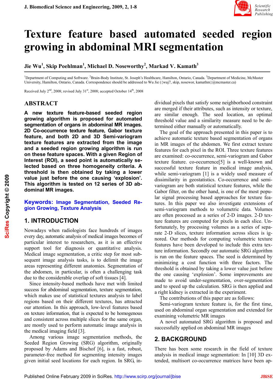 J. Biomedical Science and Engineering, 2009, 2, 1-8 Published Online February 2009 in SciRes. http://www.scirp.org/journal/jbise JBiSE 1 Texture feature based automated seeded region growing in abdominal MRI segmentation Jie Wu1, Skip Poehlman1, Michael D. Noseworthy2, Markad V. Kamath3 1Department of Computing and Software. 2Brain-Body Institute, St. Joseph’s Healthcare, Hamilton, Ontario, Canada. 3Department of Medicine, McMaster University, Hamilton, Ontario, Canada. Correspondence should be addressed to Wu Jie ({wuj7, skip, nosewor, kamathm}@mcmaster.ca) Received July 2nd, 2008; revised July 31st, 2008; accepted October 14th, 2008 ABSTRACT A new texture feature-based seeded region growing algorithm is proposed for automated segmentation of organs in abdominal MR images. 2D Co-occurrence texture feature, Gabor texture feature, and both 2D and 3D Semi-variogram texture features are extracted from the image and a seeded region growing algorithm is run on these feature spaces. With a given Region of Interest (ROI), a seed point is automatically se- lected based on three homogeneity criteria. A threshold is then obtained by taking a lower value just before the one causing ‘explosion’. This algorithm is tested on 12 series of 3D ab- dominal MR images. Keywords: Image Segmentation, Seeded Re- gion Growing, Texture Analysis 1. INTRODUCTION Nowadays when radiologists face hundreds of images every day, automatic analysis of medical images becomes of particular interest to researchers, as it is an effective support tool for diagnosis or quantitative analysis. Medical image segmentation, a critic step for most sub- sequent image analysis tasks, is to delimit the image areas representing different anatomies. Segmentation of the abdomen, in particular, is often a challenging task due to the considerable overlap of soft tissues [4]. Since intensity-based methods have met with limited success for abdominal segmentation, texture segmentation, which makes use of statistical textures analysis to label regions based on their different textures, has attracted our attention. In this approach, low-level features based on texture information, that is expected to be homogenous and consistent across multiple slices for the same organ, are mostly used to perform automatic image analysis in the medical imaging field [3]. Among various image segmentation methods, the Seeded Region Growing (SRG) algorithm, originally proposed by Adams and Bischof [6], is a fast, robust, parameter-free method for segmenting intensity images given initial seed locations for each region. In SRG, in- dividual pixels that satisfy some neighborhood constraint are merged if their attributes, such as intensity or texture, are similar enough. The seed location, an optimal threshold value and a similarity measure need to be de- termined either manually or automatically. The goal of the approach presented in this paper is to achieve automatic texture based segmentation of organs in MR images of the abdomen. We first extract texture features for each pixel in the ROI. Three texture features are examined: co-occurrence, semi-variogram and Gabor texture feature. co-occurrence[5] is a well-known and successful texture feature in medical image analysis, while semi-variogram [1] is a widely used measure of dissimilarity in geostatistics. Co-occurrence and semi- variogram are both statistical texture features, while the Gabor filter, on the other hand, is one of the most popu- lar signal processing based approaches for texture fea- tures. In this paper we also investigate extensions of semi-variogram methods to volumetric data. Volumes are often processed as a series of 2-D images. 2-D tex- ture features are computed for pixels in each slice. Un- fortunately, by processing volumes as a series of sepa- rate 2-D slices, texture information across slices is ig- nored. Our methods for computing volumetric texture features have been developed to include this extra tex- ture information. Secondly our automatic SRG algorithm is run on the feature spaces. The seed is determined by minimizing a cost function with three factors. The threshold is obtained by taking a lower value just before the one causing ‘explosion’. Some improvements are made to avoid under-segmentation, over-segmentation and to speed up the calculation. SRG is then applied and a right kidney is extracted in the experiment. The contributions of this paper are as follows: Semi-variogram texture feature is, for the first time, used on abdominal organ segmentation and extended for examining volumetric MR images A novel automated SRG algorithm is proposed and successfully applied on abdominal MR images 2. BACKGROUND There has been some research in the field of texture analysis in medical image segmentation: In [10] 3D ex- tended, multisort co-occurrence matrices have been ap- SciRes Copyright © 2009  2 J. Wu et al. / J. Biomedical Science and Engineering 2 (2009) 1-8 SciRes Copyright © 2009 JBiSE plied on MRI brain datasets. Karkanis et al. [11] applied a multilayer feed-forward neural network based on sec- ond order gray level statistics to classify cancer regions in colonoscopic images. In [12] statistical, gradient and Gabor filter features are used to segment prostatic ade- nocarcinoma. Among all, co-occurrence matrices are the most widely used texture feature. In the medical imaging field, SRG has been success- fully used to segment medical images for different pur- poses, for cervical cancer [7], extraction of cerebral blood vessels [8] and breast cancer detection [9]. There are also some trials on automating the SRG algorithm: Whitney et al. [14] overcomes the need to manually se- lect threshold values by analyzing the histogram of voxel similarity to automatically determine a stopping criterion, but they still require the user to choose a seed point. In [2] Law et al. proposed a Genetic Algorithm based seed selection method and a threshold value optimization method, but their algorithm has the problem of possible under-segmentation and speed can also be an issue al- though they did not address them. 3. METHODOLOGY Our system consists of two stages: i) After MR images are loaded into the system, each pixel in the ROI is processed and three features: co-occurrence and semi- variogram are extracted respectively; ii) Automated SRG algorithm is applied on texture feature space and in the end a region grown out of the seed is obtained. Figure 1 illustrates the system diagram. 4. FEATURE EXTRACTION Pixel-level feature extraction is used to discover the similarities between pixels. The intensity-based method is very straightforward: the gray-level of each pixel is its feature. But texture feature extraction is more complicated. While there are generally two directions on texture analysis: “all-pairs” approach [13], where the local tex- ture is calculated by all pixels in the neighborhood; and “direction distance pairs” approach [3], where local texture is calculated for every direction and distance, we adopted “direction distance pairs” approach, as it takes various permutations of pixels into consideration. Figure 2 shows how distance and directions are defined. Figure 1. system diagram Figure 2. distance and directions 4.1. Co-occurrence Grey level co-occurrence texture features were proposed by Haralick [5] in 1973 to extract second order statistics from an image. The grey level co-occurrence matrices (GLCM) was defined as a matrix of frequencies at which two pixels (in specified direction and distance) occur in the image. This matrix is square with dimension Ng, where Ng is the number of grey levels in the image. In MR images, the number of grey levels is very big compared to normal pictures. An image with 256 grey levels will have a 256*256 co-occurrence matrix, while one with 1400 gray levels will have a 1400*1400 co- occurrence matrix. Binning strategy thus becomes of great importance on the reduction of grey levels in a MR image in terms of its ability of combining several inten- sities into a single intensity level, or a bin. We adopted clipped binning strategy where one large bin is allocated for low intensity gray levels (0-I1), one for high intensity gray levels (I2 and above) and 30 equal bins are allocated for the remaining intensity gray levels. The low intensity gray level I1 and high intensity gray level I2 are determined by the image histogram. The low intensity gray level I1 is set to be the value of first valley, as pixels with gray levels from 0 to it are mostly background pixels. The high intensity gray level I2 is chosen as the first one with very few pixels, as these pixels are trivial. After binning a GLCM is created for a 3*3 neighbor- hood of each pixel instead of an image. Four directions Figure 3. a sample histogram 0° 45° 90° 135° d=1 0° 45° 90° 135° d=1 0° 45° 90° 135° d=1 MRI Load Semi - variogram Feature Extraction Segmentation 3D Semi-variogram Determine a seed Seeded Region Growing Obtain Threshold Co-occurrence Gabor MRI Load Semi - variogram Feature Extraction Segmentation 3D Semi-variogram Determine a seed Seeded Region Growing Obtain Threshold Co-occurrence Gabor  J. Wu et al. / J. Biomedical Science and Engineering 2 (2009) 1-8 3 SciRes Copyright © 2009 JBiSE (0°, 45°, 90°, 135°) and distance=1 are used to find pairs of pixels. Once the GLCM has been created, Haralick then de- scribed 14 statistics that can be calculated with the intent of describing the texture of the image: These 14*4=56 features consist of the co-occurrence texture feature space for each pixel. 4.2. Gabor Gabor wavelets are one of the most popular signal proc- essing based approaches for texture feature. The 2-D Gabor functions are Gaussians modulated by complex sinusoids as follows: )2exp( 22 exp 2 1 ),( 2 2 2 2 Wjx yx yx yx yx π σσ σπσ ψ ⎟ ⎟ ⎠ ⎞ ⎜ ⎜ ⎝ ⎛−−= where W is the modulation frequency, and σ x and σ y are the standard deviations of the two-dimension Gaus- Table 1. Haralick Texture Features Feature Formula Energy () 2 , ∑∑ ij jip Correlation () () () yx ij yx jipji σσ μμ ∑ ∑ −− , where μ x, μ y, σ x, σ y are the means and standard deviations of px, py, the partial probability density functions Inertia ()() ∑ ∑ − ij jipji , 2 Entropy () ()() 4 ,log, fjiPjiP ij =− ∑∑ Inverse Difference Moment () () ∑∑ −+ ij jip ji , 1 1 2 Sum Average () 6 2 2fiip g N iyx= ∑=+ where x and y are the coordinates(row and column) of an entry in the co-occurrence matrix, and px+y is the probability of co-occurrence matrix coordinates summing to x+y Sum Variance () () ipfi yx N i g+ = ∑−2 2 26 Sum Entropy () () { } ipip yx N iyx g+ =+ ∑ −log 2 2 Difference Average () 9 1 0fipi yx N i g= − − = ∑ Difference Variance () () ipfi yx N i g− − = ∑− 1 0 2 9 Difference Entropy () () { } ipip yx N iyx g− − =− ∑ −log 1 0 Information measure of correlation 1 () HYHX HXYf ,max 1 4− Information measure of correlation 2 () [ ] () 2/1 4 22exp1 fHXY −−− where HX and HY are the entropies for px, py, HXY1= () ()() () jpipjiP yx ij log, ∑ ∑ − HXY2= ()( )() ( ) () jpipjpip yx ij yx log ∑ ∑ − Maximal Correlation Coefficient Square root of the second largest eigenvalue of Q, where ∑ =)()( ),(),( ),( kpip kjpkip jiQ yx K sian distribution along x and y directions. The Gabor filter masks work as orientation and scale tunable detec- tors. The statistics of these microfeatures in a given re- gion can be used to capture the underlying texture in- formation. Zhang et al in [15] introduced a Gabor wavelet based texture representation for content based image retrieval. They attempted to find images or regions with the same texture and achieved satisfactory results. In our study, for each pixel we first apply Gabor filters with different scale and orientations on its 3*3 neighborhood window: ∑ ∑ = xy mn yxGnmE ),(),( (9) where E(m,n) is the summation of Gabor wavelet transform of each pixel in the image with different scale m and orientation n. A mean and a standard deviation of the magnitude of the transformed coefficients are then calculated to rep- resent the homogeneous texture features: HW nmE mn * ),( = μ (10) () HW yxG xy mnmn mn * ),( 2 ∑∑ − = μ σ (11) In our experiment 1 scale and 4 orientations are used, where scale is 1 and orientations are 0, 45, 90 and 135 respectively. A feature vector is thus generated with its mean and standard deviation. 4.3. Two Dimensional Semi-variogram We extracted 2D semi-variogram feature from every pixel in the region of interest (ROI) with the following steps[1]: First, for every pixel, a 3*3 pixel neighbouring win- dow was considered. Four directional variograms (0°, 45°, 90°, 135°) and distance d=1 were computed for all combinations in the window. The semi-variogram was then computed using the mean Square-Root Pair Difference [] ∑ = ′′ −= N i yxGyxG N hr 1 ),(),( 1 )( where G(x, y) is the gray level for the pixel (x, y). Example: Given the following 3*3 neighbouring window: 110 323 211 For d =1, direction =0°, 33.06/2 6/)011110( 6/)111032232111( == +++++= −+−+−+−+−+−= Second, directional features were transformed to rota- tion-invariant features: the mean, standard deviation and sum of perpendicular ratios  4 J. Wu et al. / J. Biomedical Science and Engineering 2 (2009) 1-8 SciRes Copyright © 2009 JBiSE ]////log[ 4513513545090900 γ γ γ γ γ γ γ γ +++ 4.4. Semi-variogram for Volumetric Data We present a new approach for calculating Semi- variogram texture features for volumetric images that will allow capturing the characteristic of the texture in 3D image data. As opposed to two dimensional Semi-variogram tex- ture features based on the spatial dependence of gray levels within a specific slice, Semi-variogram for volu- metric data is based on the spatial dependence of intensi- ties from the current slice and its two neighboring slices (one above and one below). Now a GLCM is created for a 3*3*3 neighborhood of each pixel in a specific slice. Four directions (0°, 45°, 90°, 135°) and distance 1 are used to find pairs of pixels. The semi-variogram was then computed using the mean Square-Root Pair Difference of not only the pair of pix- els in the same slice but also in the ones a slice above and a slice below the current slice. For example, when direction=0° and distance=1, the mean Square-Root Pair Difference is calculated as follows: ∑ =+++− +−++− +++− =N izyxGzyxG zyxGzyxG zyxGzyxG h 12 2 2 )]1,1,1(),,([ )]1,1,1(),,([ )],1,1(),,([ )( γ Following this directional features were transformed to rotation-invariant features just like in the two dimen- sional approach. 5. AUTOMATED SEEDED REGION GROWING As illustrated in Figure 4, there are three important steps in our automated SRG algorithm. A seed is a perquisite and we need to automatically select a seed point replac- ing the selection through user interaction. With the given seed SRG can start to grow, but a threshold value has to be determined to only cover the reasonable pixels. 5.1. Selection of a Seed Point The proposed seed point determination method is based on a cost-minimization approach. An ideal candidate seed point should have these properties: i. It should be inside the region and near the center of Figure 4. volumetric data the region ii. Assume most of the pixels in the ROI belong to the region (i.e. ROI is not too big compared to the region), the feature of this seed point should be close to the re- gion average iii. The distances from the seed pixel to its neighbors should be small enough to allow continuous growing According to these criteria, a cost function is built by adding three sub-functions corresponding to the three criteria respectively: i. The spatial distance from the pixel to the center point of the ROI ii. The Euclidean distance on feature space from the pixel to the centroid of the ROI iii. The sum of the Euclidean distance on feature space from the pixel to its neighbors We want to give equal weight to the three sub-func- tions in the cost function. However, as they have differ- ent quantities, we need to multiply three weights: w1, w2 and w3 to balance them, as follows: ( )() ( ) yxgwyxgwyxgwyxf ,,,),( 332211 ×+× + × = Thus, cost function is applied to every pixel in the ROI and the one with a minimum value is chosen as our seed. Some previous researchers have used Genetic Al- gorithm (GA) methods to minimize their fitness function and obtain the seed, but we choose not to do so. First our ROI is not big and our pixel number can be kept rea- sonably small. Second the SRG itself is a robust algo- rithm that is not very sensitive to the choice of the seed pixel. Third the GA algorithm is much more complicated than our straightforward algorithm. In a small sample space, on a not very critical problem, the faster and sim- pler way maybe better. 5.2. Seeded Region Growing Given a seed point, the region growing method searches the seed point’s neighbors to determine whether they belong to the same region. If they are determined to be so, their neighbors are searched. The process is recursively executed until no more new neighbors can be added to the region. Now it comes to the question of “How to determine whether a neighbor pixel belongs to the same region?” The criterion is when the distance is lower than a thresh- old value a neighbor point is added. So we need to de- termine the distance measure, linkage strategy, connec- tivity strategy and a threshold value (elaborated in next section). Distance measure: we use the Euclidean distance in the feature space as the distance measure. For example, with the semi-variogram texture feature, the distance between two pixels is the Euclidean distance of their semi-variogram feature vectors. Linkage strategy: we tried both single linkage strategy and centroid linkage strategy. Single linkage, in which pairs of neighboring pixels are compared for merging, is one of the conceptually simplest approaches. While in Z Slice 1 Slice 2 Slice 3  J. Wu et al. / J. Biomedical Science and Engineering 2 (2009) 1-8 5 SciRes Copyright © 2009 JBiSE centroid linkage, a pixel’s value is compared with the mean of an already existing but not necessarily com- pleted region. We chose single linkage strategy over centroid linkage because it is faster and more memory- efficient considering the calculation of texture features and recursively running SRG requires much memory. Connectivity strategy: in 2D region growing, there are two connectivity strategies that people use: four-neighbor and eight-neighbor. Four-neighbor region growing checks only the vertically and horizontally connected four neighbors, while eight-neighbor region growing checks vertically, horizontally and diagonally connected eight neighbors. The choice of neighbor connection strategy is usually case dependent. By our visual inspection of the segmented images from these two methods, the shapes delineated by four-neighbor methods are closer to the actual shapes than eight-neighbor methods. It is noted that four-neighbor usually produces more conservative or restrictive shapes than eight-neighbor. In our case, eight-neighbor explodes faster because the region grows more aggressively. When we try to determine the thresh- old value that is just before explosion, it is prone to re- sult in under-segmentation. Thus we use four-neighbor region growing approach. 5.3. Optimization of Threshold Value An optimal threshold value is the value that can make a stop to the region growing and the obtained region is optimal. It is desirable that the threshold value is high enough to extract the whole region; however if the threshold value is higher than the optimal one, the ex- tracted region may grow over the actual region boundary and grow to a much larger region. This case is called ‘explosion’ [2]. Our idea is to find the highest threshold value just be- fore this explosion. So our algorithm starts from a low threshold value and increases it by 1. With each thresh- old value we perform a SRG algorithm and evaluate its result. This is the first pass. When it comes to a value causing explosion, we retrieve the last value not causing explosion, and from that value to the explosion value, by a step of 0.1, perform another pass, and retrieve the value just before explosion. That value is our optimal threshold value. But in this algorithm we have a few issues to solve: i. How to quantify an explosion? If we plot the ‘threshold value’ vs ‘number of pixels in the region’, the explosion value must have a big slope because the threshold value always increases by the same amount whereas the number of pixels in the region has increased significantly. Thus this slope value: (#pixels in the re- gion/threshold value change) is used to check explosion. If the slope value is larger than a big value, explosion has occurred. ii. How to avoid under-segmentation? The algorithm may stop if an explosion occurs before it is supposed to stop. In this case, the resulting region is smaller than the actual region and this is an under-segmentatation. To avoid stopping region growing too early, the algorithm does not stop immediately when it finds an explosion. It finds all the explosions and does not stop until their #pixels are more than the total number of pixels in the ROI. By then, we pick the last explosion with the most #pixels as the actual explosion. iii. How to avoid over-segmentation? To avoid over- segmentation, two stop criteria are added to the algo- rithm. One is the #pixels in the resulting region cannot exceed the #pixels in the ROI. Second is the leftmost, rightmost, uppermost and lowermost pixels in the resulting region should not exceed the spatial location of these four pixels of ROI by some extent. We allow them to exceed 20 pixels, but this is flexible and case dependent. iv. How to solve the speed problem? One of our big- gest concerns about this algorithm is the speed since it has to do two-pass scans and for every threshold value SRG has to be performed and on texture feature space the process of texture feature extraction and distance calculation is much more complex than simple intensity features. However, we noticed a fact that can save cal- culation time: when threshold value increases, the re- sulting region is always the super set of the previous resulting region. The reason is obvious: the pixels that can be added to the region with a lower threshold value definitely can be added with a higher threshold value. In other words, with every new threshold value, we do not need to perform a SRG from scratch. We can perform a SRG based on the resulting region obtained from previ- ous lower threshold value. From the resulting region, we extract their boundaries and start to grow on these boundary pixels with the new threshold value. In this way calculations are saved and speed is much improved. With these issues explained and solved, we can now proceed with the application of the algorithms. 6. EXPERIMENTS AND DISCUSSION 6.1. Data The algorithms are run on 3D abdominal MR images obtained from a GE 3T scanner at the Brain Body Insti- tute of St. Joseph’s Healthcare. The image set contains 12 series of 512*512 gray-scale images in DICOM fomat. No preprocessing is applied. 6.2. Segmentation The algorithms are implemented with matlab and Figure 5 shows a screenshot of our segmentation system. In Manual Mode users have the options to choose a specific threshold or give a range of threshold for the program to look for the optimal threshold value. In Auto Mode users only need to select a rectangle ROI. When a ROI is se- lected, the system can start segmentation of organs automatically without any user intervention.  6 J. Wu et al. / J. Biomedical Science and Engineering 2 (2009) 1-8 SciRes Copyright © 2009 JBiSE Figure 5. the user interface implemented in the algo- rithm (Manual Mode) Figure 6. the user interface implemented in the algo- rithm (Autol Mode) In the seed point retrieval algorithm, every pixel in the ROI is evaluated by the cost function and the one with minimum cost function is our seed point. The resultant point is examined and found to be within the region, near center and have similar feature values with most of the pixels in the region, which is required. Figure 6 is an example of the chosen seed pixel. In the threshold determination algorithm, we test incre- mental threshold values from a starting value, which is given the minimum value of the distances between the seed point and its neighbors since it has been minimized through the cost function minimization process. Follow- ing this, we apply the threshold deter- mination algo- rithm described in 5.3. Figure 7 is a sample plot of this optimization process. X-axis is the threshold value and Y-axis is the count of pixels in the resultant region. We apply SRG on every incremental threshold value and when it reaches 34, an explosion is detected. The algo- Figure 7. a sample seed pixel selected by the algorithm Figure 8. a sample threshold optimization plot rithm then does a second pass from 33 to 34 by 0.1, and the value 33.8 is the one just before the explosion and thus chosen to be the threshold value. Then we ran our algorithms on left kidneys of ab- dominal MR images and obtained segmentation results for both co-occurrence and semi-variogram SRG respec- tively. Figure 8 shows a sample result for 2D semi- variogram, Figure 9 for co-occurrence, Figuer 10 for Gabor and Figure 11 for 3D semivariogram. If we compare these four methods, from the perform- ance point of view, based on the results from our images, we find them comparable to each other. Figure 9. a segmentation result on left kidney us- ing 2D semi- variogram based SRG Figure 10. a segmentation result on left kidney us- ing co-occurrence based SRG  J. Wu et al. / J. Biomedical Science and Engineering 2 (2009) 1-8 7 SciRes Copyright © 2009 JBiSE Figure 11. a segmentation result on left kidney using Gabor based SRG Figure 12. a segmentation result on left kidney using 3D semi-variogram based SRG From the speed point of view, 2D semi-variogram based SRG performs much faster than co-occurrence based SRG. This is reasonable because for every pixel a co-occurrence matrix has to be built first, followed by Haralick’s fourteen statistics. However semi- variogram features can be extracted from the neighboring window directly. Gabor filter method performs faster than co- occurrence and slower than 2D semi-variogram method. 3D semi-variogram method needs to process multiple slices and thus needs more computation time than 2D semi-variogram. 7. CONCLUSION In this paper we proposed our texture feature-based automated SRG algorithm on abdominal organ segmen- tation. The benefit of this algorithm is obvious, as it pro- vides a parameter-free production environment to allow minimum user intervention. This can be especially help- ful for batch work or to novice computer users. We also proposed the usage of 2D and 3D semi- variogram as a texture feature in medical organ segmen- tation. They are compared with the co- occurrence method and Gabor filter method and found to be a feasi- ble texture feature in organ segmentation. But our approach does have drawbacks. Texture fea- ture based methods all have the assumption that the re- gion should have texture homogeneity. For organs with complex texture like the heart, this approach might not work well [14]. In our experiment the segmentation re- sults leave some pixels inside kidney out also because these pixels have different texture homogeneity with the others. This, on the other hand, can help detect cysts or tumors inside organs. Our future work includes investigation of other 2D and 3D texture features and evaluation of their performance. We are also combining this approach with other edge detecting or deformable model approaches to get a better boundary. ACKNOWLEDGEMENT This work is in part supported by Natural Sciences and Engineering Research Council of Canada (NSERC) granted to Dr. Markad V. Ka- math. REFERENCES [1] P. Maillard, (2001) “Developing methods of texture analysis in high resolution images of the Earth”, X Simpósio Brasileiro de Sensoriamento Remoto, São Paulo-SP: Fábrica da Imagem. 1-11. [2] T.-Y. Law and P. A. Heng, (2000) “Automated extraction of bronchus from 3-D CT images of lung based on genetic algo- rithm and 3-D region growing”, Proc. SPIE 3979, Medical Im- aging 2000: Image Processing, 906-916. [3] R. Susomboon, D. S. Raicu, and J. D. Furst, (2006)“Pixel-Based Texture Classification of Tissues in Computed Tomography”, CTI Research Symposium, Chicago, April 2006. [4] J. E. Koss, F. D. Newman, T. K. Johnson, D. L. Kirch, (1999) “Abdominal organ segmentation using texture transform and a Hopfield neural network”, IEEE Trans. Medical Imaging, Vol.18, 640-648. [5] R. M. Haralick, K. Shanmugam, and I. Dinstein, (1973) “Texture Features for Image Classification”, IEEE Trans. On Systems, Man, and Cybernetics, Vol. Smc-3, No.6, 610-621. [6] R. Adams, L Bischof, (1994) “Seeded region growing”. IEEE Trans. Pattern Anal. Machine Intell. 16, 641-647. [7] N. A. Mat-Isa, M. Y. Mashor & N. H. Othman, (2005) “Seeded Region Growing Features Extraction Algorithm; Its Potential Use in Improving Screening for Cervical Cancer”. International Journal of the Computer, the Internet and Management. (ISSN No: 0858-7027). Vol. 13. No. 1. January-April. [8] Y. Tuduki, K. Murase, M. Izumida, H. Miki, K. Kikuchi, K. Murakami & J. Ikezoe (2000). “Automated Seeded Region Growing Algorithm for Extraction of Cerebral Blood Vessels from Magnetic Resonance Angiographic Data”. Proceedings of The 22nd Annual International. Conference of the IEEE Engineering in Medicine and Biology Society. 3. 1756-1759. [9] P. A. Venkatachalam, U. K.Ngah, A. F. M. Hani& A. Y. M. Shakaff, (2002). “Seed Based Region Growing Technique in Breast Cancer Detection and Embedded Expert System”. Pro- ceedings of International Conference on Artificial Intelligence in En- gineering and Technology. 464-469. [10] V. A. Kovalev, F. Kruggel, H.-J Gertz, and D.Y. von Cramon. (2001) “Three-dimensional texture analysis of MRI brain data- sets.” IEEE Trans. on Medical Imaging, 20(5): 424-433. [11] S. A. Karkanis, et al., (1999) “Detecting abnormalities in colono- scopic images by texture descriptors and neural networks,” Proc. of the Workshop Machine Learning in Med. App., 59-62. [12] A. Madabhushi, M. Feldman, D. Metaxas, D. Chute, and J. Tomaszewski. (2003) “A novel stochastic combination of 3D tex- ture features for automated segmentation of prostatic adenocarci- noma from high resolution MRI.” Medical Image Computing and Computer-Assisted Intervention, volume 2878 of Lecture Notes in  8 J. Wu et al. / J. Biomedical Science and Engineering 2 (2009) 1-8 SciRes Copyright © 2009 JBiSE Computer Science, pp. 581-591. Springer-Verlag. [13] M. Kalinin, D. S. Raicu, J. Furst, and D. S. Channin, “A classification Approach for anatomical regions segmentation”, IEEE Int. Conf. on Image Processing, 2005. [14] B. W. Whitney, N. J. Backman, J. D. Furst, D. S. Raicu, (2006) “Single click volumetric segmentation of abdominal organs in Computed Tomography images”, Proceedings of SPIE Medical Imaging Conference, San Diego, CA, Februar. [15] D. Zhang, A. Wong, M. Indrawan, G. Lu, (1990) Content-Based Image Retrieval Using Gabor Texture Features, IEEE Transac- tions PAMI, 12:7, 629-639. [16] J. Wu, S. Poehlman, M. D. Noseworthy, M. Kamath, (2008) Texture Feature based Automated Seeded Region Growing in Abdominal MRI Segmentation, 2008 International Conference on Biomedical Engineering and Informatics, Sanya, China, May 27-30. |