Paper Menu >>
Journal Menu >>
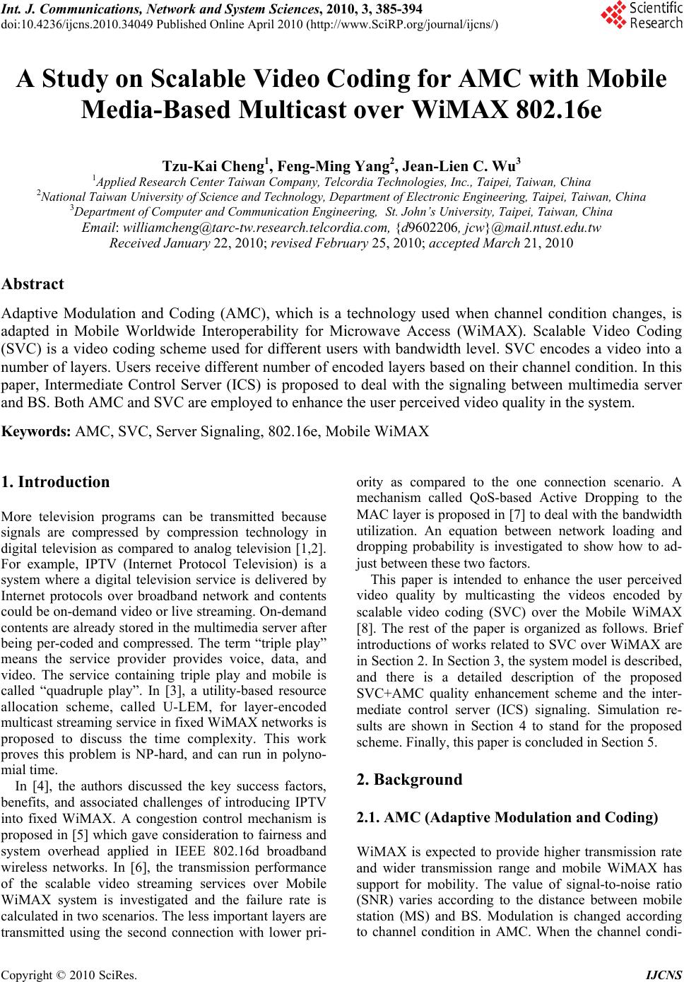 Int. J. Communications, Network and System Sciences, 2010, 3, 385-394 doi:10.4236/ijcns.2010.34049 blished Online April 2010 (http://www.SciRP.org/journal/ijcns/) Copyright © 2010 SciRes. IJCNS Pu A Study on Scalable Video Coding for AMC with Mobile Media-Based Multicast over WiMAX 802.16e Tzu-Kai Cheng1, Feng-Ming Yang2, Jean-Lien C. Wu3 1Applied Research Center Taiwan Company, Telcordia Technologies, Inc., Taipei, Taiwan, China 2National Taiwan University of Science and Technology, Department of Electronic Engineering, Taipei, Taiwan, China 3Department of Computer and Communication Engineering, St. John’s University, Taipei, Taiwan, China Email: williamcheng@tarc-tw.research.telcordia.com, {d9602206, jcw}@mail.ntust.edu.tw Received January 22, 2010; revised February 25, 2010; accepted March 21, 2010 Abstract Adaptive Modulation and Coding (AMC), which is a technology used when channel condition changes, is adapted in Mobile Worldwide Interoperability for Microwave Access (WiMAX). Scalable Video Coding (SVC) is a video coding scheme used for different users with bandwidth level. SVC encodes a video into a number of layers. Users receive different number of encoded layers based on their channel condition. In this paper, Intermediate Control Server (ICS) is proposed to deal with the signaling between multimedia server and BS. Both AMC and SVC are employed to enhance the user perceived video quality in the system. Keywords: AMC, SVC, Server Signaling, 802.16e, Mobile WiMAX 1. Introduction More television programs can be transmitted because signals are compressed by compression technology in digital television as compared to analog television [1,2]. For example, IPTV (Internet Protocol Television) is a system where a digital television service is delivered by Internet protocols over broadband network and contents could be on-demand video or live streaming. On-demand contents are already stored in the multimedia server after being per-coded and compressed. The term “triple play” means the service provider provides voice, data, and video. The service containing triple play and mobile is called “quadruple play”. In [3], a utility-based resource allocation scheme, called U-LEM, for layer-encoded multicast streaming service in fixed WiMAX networks is proposed to discuss the time complexity. This work proves this problem is NP-hard, and can run in polyno- mial time. In [4], the authors discussed the key success factors, benefits, and associated challenges of introducing IPTV into fixed WiMAX. A congestion control mechanism is proposed in [5] which gave consideration to fairness and system overhead applied in IEEE 802.16d broadband wireless networks. In [6], the transmission performance of the scalable video streaming services over Mobile WiMAX system is investigated and the failure rate is calculated in two scenarios. The less important layers are transmitted using the second connection with lower pri- ority as compared to the one connection scenario. A mechanism called QoS-based Active Dropping to the MAC layer is proposed in [7] to deal with the bandwidth utilization. An equation between network loading and dropping probability is investigated to show how to ad- just between these two factors. This paper is intended to enhance the user perceived video quality by multicasting the videos encoded by scalable video coding (SVC) over the Mobile WiMAX [8]. The rest of the paper is organized as follows. Brief introductions of works related to SVC over WiMAX are in Section 2. In Section 3, the system model is described, and there is a detailed description of the proposed SVC+AMC quality enhancement scheme and the inter- mediate control server (ICS) signaling. Simulation re- sults are shown in Section 4 to stand for the proposed scheme. Finally, this paper is concluded in Section 5. 2. Background 2.1. AMC (Adaptive Modulation and Coding) WiMAX is expected to provide higher transmission rate and wider transmission range and mobile WiMAX has support for mobility. The value of signal-to-noise ratio (SNR) varies according to the distance between mobile station (MS) and BS. Modulation is changed according to channel condition in AMC. When the channel condi- 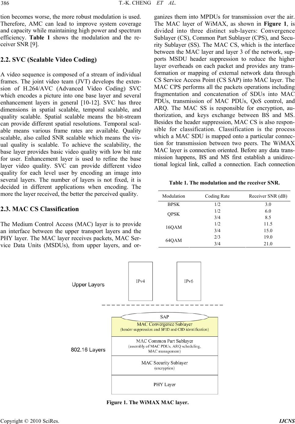 T.-K. CHENG ET AL. 386 tion becomes worse, the more robust modulation is used. Therefore, AMC can lead to improve system coverage and capacity while maintaining high power and spectrum efficiency. Table 1 shows the modulation and the re- ceiver SNR [9]. 2.2. SVC (Scalable Video Coding) A video sequence is composed of a stream of individual frames. The joint video team (JVT) develops the exten- sion of H.264/AVC (Advanced Video Coding) SVC which encodes a picture into one base layer and several enhancement layers in general [10-12]. SVC has three dimensions in spatial scalable, temporal scalable, and quality scalable. Spatial scalable means the bit-stream can provide different spatial resolutions. Temporal scal- able means various frame rates are available. Quality scalable, also called SNR scalable which means the vis- ual quality is scalable. To achieve the scalability, the base layer provides basic video quality with low bit rate for user. Enhancement layer is used to refine the base layer video quality. SVC can provide different video quality for each level user by encoding an image into several layers. The number of layers is not fixed, it is decided in different applications when encoding. The more the layer received, the better the perceived quality. 2.3. MAC CS Classification The Medium Control Access (MAC) layer is to provide an interface between the upper transport layers and the PHY layer. The MAC layer receives packets, MAC Ser- vice Data Units (MSDUs), from upper layers, and or- ganizes them into MPDUs for transmission over the air. The MAC layer of WiMAX, as shown in Figure 1, is divided into three distinct sub-layers: Convergence Sublayer (CS), Common Part Sublayer (CPS), and Secu- rity Sublayer (SS). The MAC CS, which is the interface between the MAC layer and layer 3 of the network, sup- ports MSDU header suppression to reduce the higher layer overheads on each packet and provides any trans- formation or mapping of external network data through CS Service Access Point (CS SAP) into MAC layer. The MAC CPS performs all the packets operations including fragmentation and concatenation of SDUs into MAC PDUs, transmission of MAC PDUs, QoS control, and ARQ. The MAC SS is responsible for encryption, au- thorization, and keys exchange between BS and MS. Besides the header suppression, MAC CS is also respon- sible for classification. Classification is the process which a MAC SDU is mapped onto a particular connec- tion for transmission between two peers. The WiMAX MAC layer is connection oriented. Before any data trans- mission happens, BS and MS first establish a unidirec- tional logical link, called a connection. Each connection Table 1. The modulation and the receiver SNR. ModulationCoding Rate Receiver SNR (dB) BPSK 1/2 3.0 1/2 6.0 QPSK 3/4 8.5 1/2 11.5 16QAM 3/4 15.0 2/3 19.0 64QAM 3/4 21.0 Figure 1. The WiMAX MAC layer. Copyright © 2010 SciRes. IJCNS 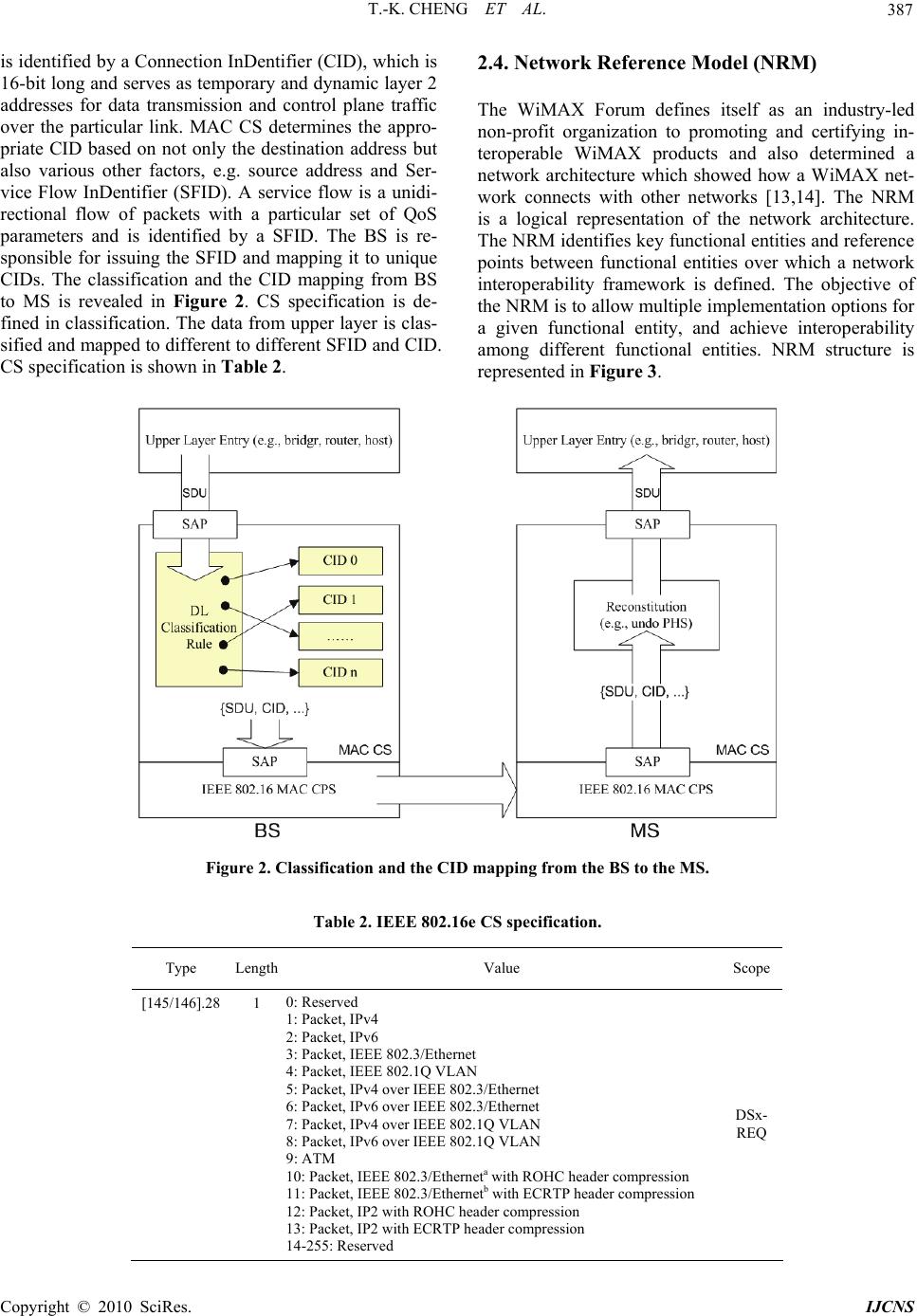 T.-K. CHENG ET AL. 387 is identified by a Connection InDentifier (CID), which is 16-bit long and serves as temporary and dynamic layer 2 addresses for data transmission and control plane traffic over the particular link. MAC CS determines the appro- priate CID based on not only the destination address but also various other factors, e.g. source address and Ser- vice Flow InDentifier (SFID). A service flow is a unidi- rectional flow of packets with a particular set of QoS parameters and is identified by a SFID. The BS is re- sponsible for issuing the SFID and mapping it to unique CIDs. The classification and the CID mapping from BS to MS is revealed in Figure 2. CS specification is de- fined in classification. The data from upper layer is clas- sified and mapped to different to different SFID and CID. CS specification is shown in Table 2. 2.4. Network Reference Model (NRM) The WiMAX Forum defines itself as an industry-led non-profit organization to promoting and certifying in- teroperable WiMAX products and also determined a network architecture which showed how a WiMAX net- work connects with other networks [13,14]. The NRM is a logical representation of the network architecture. The NRM identifies key functional entities and reference points between functional entities over which a network interoperability framework is defined. The objective of the NRM is to allow multiple implementation options for a given functional entity, and achieve interoperability among different functional entities. NRM structure is represented in Figure 3. Figure 2. Classification and the CID mapping from the BS to the MS. Table 2. IEEE 802.16e CS specification. Type Length Value Scope [145/146].28 1 0: Reserved 1: Packet, IPv4 2: Packet, IPv6 3: Packet, IEEE 802.3/Ethernet 4: Packet, IEEE 802.1Q VLAN 5: Packet, IPv4 over IEEE 802.3/Ethernet 6: Packet, IPv6 over IEEE 802.3/Ethernet 7: Packet, IPv4 over IEEE 802.1Q VLAN 8: Packet, IPv6 over IEEE 802.1Q VLAN 9: ATM 10: Packet, IEEE 802.3/Etherneta with ROHC header compression 11: Packet, IEEE 802.3/Ethernetb with ECRTP header compression 12: Packet, IP2 with ROHC header compression 13: Packet, IP2 with ECRTP header compression 14-255: Reserved DSx- REQ C opyright © 2010 SciRes. IJCNS  T.-K. CHENG ET AL. 388 3. SVC+AMC Quality Enhancement and ICS Signaling 3.1. System Model When an MS requests a video, it sends the messages to the BS, and the BS then forwards the request to the mul- timedia server. When adapting SVC, which encodes a frame into several layers, the multimedia server which stores the videos performs the encoding procedure and transmits the layers to the BS. For all MSs who are watching the same video, the BS grouped them based on their feedback channel condition. The group with better channel condition gets more layers. On the contrary, the group with worse channel condition gets fewer layers. However, the BS can not distinguish the layer ID re- ceived from the multimedia server. In order to solve this problem, an Intermediate Control Server (ICS) is newly added in the system, see Figure 4. A WiMAX network is served by an ICS. After executing the videos in the mul- timedia server, the ICS forwards the SVC-encoded layers to BS. Figure 3. Network reference model. Figure 4. The proposed system model with a newly added ICS. Copyright © 2010 SciRes. IJCNS  T.-K. CHENG ET AL. 389 In our proposed scheme, SVC is implemented to en- code a frame into three layers. Layer 0 is meant to be the base layer, which contains the most important informa- tion. Layer 1 and layer 2 belong to the enhancement lay- er, which carries less information as compared to layer 0. In order to assure the video quality perceived by user within worse channel condition, layer 0 is encoded to carry 50% information of the original frame. After re- ceiving and decoding layer 1 with layer 0, the containing information is refined to 75%. Users with best channel condition get all three layers, the frame which is decoded by combining layer 0, layer 1, and layer 2 is the same as the original transmitted frame. The retrieval frames are shown in Figure 5. 3.2. The ICS Signaling The multimedia server encodes the video into three lay- ers in the application layer. All layers are packetized and added different protocol headers from the upper layer to lower layer, the BS could not distinguish the layer ID. An ICS is used to solve this problem. An ICS is indi- vidually set between multimedia server and the BS for flexibility and extensibility of many applications pro- vided by different operators in the future. The major task of ICS is to re-packetize the packets received from mul- timedia server so that the BS recognizes the layer IDs. The proposed system model with network layers is shown in Figure 6. When the ICS receives the SVC-encoded layer packet, it decodes the packet in the application layer and gets the layer ID information. While transmitting to the BS, the ICS re-packages the SVC-encoded frame by adding the layer ID information in the reserved filed of each net- work protocol header. The Network Abstraction Layer (NAL) unit [15], shown in Figure 7, defines the interface between the encoded video data itself and the possible transport layers or storage formats. Each NAL unit re- gardless of its type is encapsulated in the RTP/UDP/IP packet. The encapsulation of NAL unit is shown in Ta- ble 3. Three bits in NAL unit are used to indicate the layer ID. When the packet transmits by RTP (Real-time Trans- port Protocol), there are seven bits in the payload type filed [16]. The RTP header format is presented in Figure 8. The reserved values in payload type, which is dis- played in Table 4, are 72 to 76 [17]. We use three values, 72, 73, and 74, to indicate the layer ID. In UDP (User Datagram Protocol) header format which is shown in Figure 9, there are 8-bit protocol numbers [18]. Part of the assigned protocol numbers is presented in Table 5, the values 72-76 and 80-254 are unassigned [19], and three values, 72, 73, and 74, are used to denote the layer ID. Continuing transmitting to lower layer, the IPv4 (Int- ernet Protocol version 4) header is displayed in Figure 10 [20]. 2-bit reserved field could be used to show the layer ID. ‘00’ denotes layer 0, ‘01’ denotes layer1, and ‘10’ denotes layer2 separately. In this way, MAC layer can clearly distinguish what the received layer ID is. Figure 5. The retrieval frame of SVC. Figure 6. The proposed system model with network layers. Table 3. The encapsulation of NAL unit in RTP/UDP/IP header. IP headerUDP header RTP header NAL unit header NAL unit payload H.264 Standard Header byte H.264 Standard Header Extension byte 0 Nal_ref _idc Nal_unit_type Lyaer ID Temporal Layer ID Quality Level 1 bit 2 bit 5 bit 3 bit 3 bit 2 bit Figure 7. NAL unit header format. C opyright © 2010 SciRes. IJCNS  T.-K. CHENG ET AL. 390 Figure 8. RTP header format. Figure 9. UDP header format. Figure 10. IPv4 header format. Table 4. Partial RTP payload type. PT Encoding Name Media Type Clock Rate (Hz) 34 H.263 V 90,000 35-71 Unassigned ? 72-76 Reserved N/A N/A 77-95 Unassigned ? 96-127 Dynamic ? Table 5. Partial UDP protocol number. Decimal Octal Protocol Numbers 69 105 SIMP monitoring 70 106 SIMP polling 71 107 SIMP packet core/U 72-76 110-114 Unassigned 77 115 Backroom SIMP polling 78 116 Backroom SIMP monitoring 79 117 SIMP message generators 80-254 120-376 Unassigned 255 377 Reserved 3.3. The SVC+AMC Quality Enhancement Scheme In the SVC+AMC quality enhancement scheme, the BS multicasts different layers using different modulations based on different connections. The mapping of the layer to Connection IDentifiers (CIDs) is decided by the clas- sification rule in the MAC CS specification defined in the IEEE 802.16e standard. Three reserved value 14-255 are used to indicate the layer IDs which are “Packet, IPv4 over 802.3/Ethernet ECRTP compression SVC-enc- oded layer 0”, “Packet, IPv4 over 802.3/Ethernet ECRTP compression SVC-encoded layer 1”, and “Packet, IPv4 over 802.3/Ethernet ECRTP compression SVC- encoded layer 2”. Based on the CS classification rule, the layers are easily mapped to different CIDs. In the 802.16e OFDMA DL-MAP_IE format, there are 8-bit CIDs as- signed for this Information Element (IE). Three values in the unassigned CIDs are chosen to indicate these three connections. The SVC+AMC quality enhancement scheme groups MSs who are receiving the same channel into three groups according to their fast-feedback channel condi- tion to the BS. The fast-feedback CQICH information is allocated in the uplink subframe in OFDMA frame. These MSs who subscribe the same video are all in group 0 to receive layer 0. If there are some with better channel condition, they are grouped into group 1 to re- Copyright © 2010 SciRes. IJCNS  T.-K. CHENG ET AL. 391 ceive layer 1, so they are in group 0 and group 1 at the same time. For those MSs with the best channel condi- tion, they are grouped into group 2 to receive layer 2, therefore, they are in group 0, 1, and 2. While transmit- ting, the BS multicasts layer 0 to group 0 using QPSK through CID 0, multicasts layer 1 to group 1 using 16QAM through CID 1, and multicasts layer 2 to group 2 using 64QAM through CID 2. For this reason, users with better channel condition could enjoy better perceived video quality. 4. Simulation 4.1. Simulation Parameters The fundamental simulation parameters [21-23] are sho- wn in Table 6. Network congestion is considered in the system. Assume packet loss rates in the channel are 0.30%, 0.24%, and 0.21% while using QPSK, 16QAM, and 64QAM respectively. PSNR (Peak Signal-to-Noise Ratio) is a conventional assessment method used to assess the quality of the re- constructed images. PSNR is used to compare the simi- larity between the original frame and the retrieval frame. Each pixel in the retrieval frame is compared with each related pixel in the original frame. The equation of PSNR is shown in following. In general, when the value of PSNR reaches 30dB, it means the difference between original frame and retrieval frame is hardly recognized by human eyes. 2 10 ( 255) PSNR10 logdB MSE (1) 2 11 1 MSE, , () wh ij ij ij wh (2) 4.2. Simulation Results Simulation results are used to show the SVC+AMC quality enhancement scheme improves the user per- ceived video quality effectively. There are three methods considered in two scenarios. The first method, referred as Normal scheme, transmits the original video to MSs us- ing 16QAM without applying SVC and AMC. The sec- ond method, referred as the AMC scheme, transmits the original video which is not encoded by SVC to MSs ac- cording to their channel condition. MSs in worse channel condition receive the video using QPSK. The BS multi- casts the video to MSs in normal channel condition using 16QAM and multicasts to MSs with better channel con- dition using 64QAM. The last one is the SVC+AMC quality enhancement scheme proposed in this paper. In SVC+AMC, the BS transmits the SVC-encoded layers to all MSs using QPSK, to MSs with normal channel condi- tion using 16QAM, and to MSs in better channel condi- tion using 64QAM. We setup two different scenarios and use two videos to simulate. Scenario1 has 20 MSs which are investi- gated to the PSNR rate on Mobile WiMAX system. There is only one connection between the multimedia server and the BS, all layer-encoded videos are transmit- ted via this connection. The ICS forwards the SVC-en- coded layers to the BS. Scenario2 is basically the same as Scenario1 except the channel conditions of MSs. In Scenario1 of the first video, 20% of MSs are in worse channel condition, 40% of MSs are in normal channel condition, and 40% of MSs are in better channel condition. Therefore, there are 20 MSs in group 0, 16 MSs in group 1, and 8 MSs in group 2. The above-men- tioned three methods are employed to simulate the sce- nario. Figure 11 shows the simulation results. The aver- age values of PSNR in normal, AMC, and SVC+AMC scheme are 26.22, 27.58, and 32.18, separately. The AMC scheme is compared to the normal scheme first. The average value of PSNR in the AMC scheme is just a little higher than the normal scheme. While in the normal scheme, all MSs receive the non-encoded video using 16QAM. In normal scheme, the average PSNR in the system becomes lower because 20% of MSs receive the video in an unsuitable modulation and coding scheme and 40% of MSs with better channel condition should deserve better video quality. In the AMC scheme, all MSs receive the full video in a suitable packet loss rate according to their channel condition. Packet loss rate becomes smaller while transmitting to MSs with better channel condition using 64QAM. Packet loss occurs more often in MSs with worse channel condition because of the more robust modulation and coding scheme. For that reason, PSNR is only a little better in the AMC scheme than in normal scheme. The SVC+AMC scheme, which receives the SVC-encoded video based on their channel condition, gets the highest average PSNR. MSs in worse channel condition receive layer 0 using QPSK resulting in less packet loss, but the perceived quality is still embraceable. Two layers are transmitted to MSs Table 6. Fundamental simulation parameters. Parameter Value Channel Bandwidth 10 MHz Size of FFT 1024 Number of Sub-channels 30 OFDMA Symbol Time 102.9 μs Frame Duration 5 ms Modulation Scheme QPSK, 16QAM, 64QAM Mobility Model Random Waypoint Number of MSs 20 C opyright © 2010 SciRes. IJCNS  T.-K. CHENG ET AL. Copyright © 2010 SciRes. IJCNS 392 who are in normal channel condition using 16QAM also cause less packet loss. The result of better channel condi- tion MSs in SVC+AMC is the same to the AMC scheme, because the retrieval frame is the same as the non-en- coded one. In Scenario2 of the first video, 80% of MSs are in worse channel condition, 10% of MSs are in normal channel condition, and 10% of MSs are in better channel condition. Therefore, there are 20 MSs in group 0, 4 MSs in group 1, and 2 MSs in group 2. The average values of PSNR in three schemes are 16.15, 18.60, and 28.37. The simulation results of Scenario2 employed with these three methods is shown in Figure 12. The reason why the PSNR in the AMC scheme is higher than that in the normal scheme, and the SVC+AMC scheme gets the best quality is the same as Scenario1. However, the variation between the two scenarios is obvious. In Scenario1, PSNR ranges from 26.22 to 32.18, but PSNR ranges from 16.15 to 28.37 in Scenario2. Each MS in better channel condition whether the percentage is 10% or 40% receives almost the same level of the video quality. But PSNR is influenced more because 80% of MSs with worse channel condition. Once the packet loss rate gets higher, the value of PSNR becomes lower. The- refore, the proposed SVC + AMC scheme enhances the user perceived video quality better in the situation that the percentage of worse channel condition is larger in the system. 0.00 5.00 10.00 15.00 20.00 25.00 30.00 35.00 40.00 45.00 1163146617691106 121 136151166181 196211 226 241256 Fram e PSNR (dB) Normal AMC AMC+SVC Figure 11. 20% worse channel condition MSs, 40% normal channel condition MSs, and 40% better channel condition MSs in normal, AMC, and SVC + AMC methods in the first video. 0.00 5.00 10.00 15.00 20.00 25.00 30.00 35.00 1163146617691106121136 151 166181 196211 226 241256 Frame PSNR (dB) Normal AMC AMC+SVC Figure 12. 80% worse channel condition MSs, 10% normal channel condition MSs, and 10% better channel condition MSs in normal, AMC, and SVC + AMC methods in the first video.  T.-K. CHENG ET AL. 393 Three methods are also considered with two scenarios in the second video. The simulation results are shown separately in Figure 13 and Figure 14. In Scenario1 of the second video, 20% worse channel condition MSs, 40% normal channel condition MSs, and 40% better channel condition MSs in normal, AMC, and SVC+ AMC methods. Therefore the average values of PSNR in three schemes are 26.90, 28.30, and 33.76. In Scenario2 of the second video, 80% worse channel condition MSs, 10% normal channel condition MSs, and 10% better channel condition MSs in normal, AMC, and SVC + AMC methods. Therefore the average values of PSNR ranges are 15.91, 18.42, and 29.19. The reason why the SVC + AMC scheme performs better than the other two schemes is the same when simulating in the first video in despite Scenario1 or Scenario2, and the reason why Scenario1 performs better than Scenario2 is also the same for the first video. In summary, no matter how the percentage of the MSs in worse, normal, and better channel condition changes, the proposed SVC + AMC scheme can further enhance the user perceived video quality. When a full video adapts AMC without SVC, the video quality is almost the same as the normal scheme. According to the simula- tion results, SVC + AMC improves the user perceived video quality well, it improves more significantly when there are more users with worse channel condition. 0.00 5.00 10.00 15.00 20.00 25.00 30.00 35.00 40.00 45.00 50.00 1163146617691106 121 136 151 166181 196 211 226 241256 Frame PSNR (dB) Normal AMC AMC+SVC Figure 13. 20% worse channel condition MSs, 40% normal channel condition MSs, and 40% better channel condition MSs in normal, AMC, and SVC + AMC methods in the second video. 0.00 5.00 10.00 15.00 20.00 25.00 30.00 35.00 40.00 1163146617691106 121136151166181 196211 226 241 256 Frame PSNR (dB) Norma l AMC AMC+SVC Figure 14. 80% worse channel condition MSs, 10% normal channel condition MSs, and 10% better channel condition MSs in normal, AMC, and SVC + AMC methods in the second video. C opyright © 2010 SciRes. IJCNS  T.-K. CHENG ET AL. Copyright © 2010 SciRes. IJCNS 394 5. Conclusions We proposed an effective video quality enhancement approach applied on mobile media-based multicast over WiMAX. A signaling mechanism is designed between the multimedia server and the BS. The channel condition varies when MSs move. The BS multicasts different number of layers to MSs within different channel condi- tion using different modulation and coding scheme. MSs with worse channel condition receive fewer layers by more robust modulation and coding scheme. The signal mechanism between the multimedia server and the BS is performed by an ICS between the multimedia server and the BS. The main task of ICS is to decode the SVC-en- coded layers from multimedia server and re-package the packet with layer ID information in different protocol headers. The mapping of the layer and CID is discussed and performed in the MAC CS specification. Simulation results show that the proposed SVC to- gether with AMC can indeed effectively improve the user perceived video quality, even when there are many users with bad channel condition. The ICS signaling re- solves the problem that the BS can not distinguish the layer ID received from the multimedia server. 6. References [1] B. Fox, “Digital TV Comes Down to Earth,” IEEE Spectrum Magazine, Vol. 35, October 1998, pp. 23-29. [2] R. M. Rast, “The Dawn of Digital TV,” IEEE Spectrum Magazine, Vol. 42, October 2005, pp. 26-31. [3] W. H. Kuo, T. H. Liu and W. J. Laio, “Utility-Based Resource Allocation for Layer-Encoded IPTV Multicast in IEEE 802.16 (WiMAX) Wireless Networks,” In Proceedings of IEEE ICC, June 2007, pp. 1754-1759. [4] J. She, F. Hou, P. H. Ho and L. L. Xie, “IPTV over WiMAX: Key Success Factors, Challengers, and Solutions,” IEEE Communication Magazine, Vol. 45, August 2007, pp. 87-93. [5] O. I. Hillestad, A. Perkis, V. Genc, S. Murphy and J. Murthy, “Adaptive H.264/MPEG-4 SVC Video over IEEE 802.16 Broadband Wireless Networks,” In Pro- ceedings of IEEE Packet Video, November 2007, pp. 26-35. [6] H. H. Juan, H. C. Huang, C. Y. Huang and T. H. Chiang, “Scalable Video Streaming over Mobile WiMAX,” In Proceedings of IEEE ISCAC, May 2007, pp. 3463-3466. [7] J. C. Chiang, H. F. Lo and W.T. Lee, “Scalable Video Coding of H.264/AVC Video Streaming with QoS-Based Active Dropping in 802.16e Networks,” In Proceedings of IEEE WAINA, March 2008, pp. 1450-1455. [8] T. K. Cheng, F. M. Yang, J. L. C. Wu and I. C. Lin, “Adaptive Modulation and SVC-Encoded Video IPTV Multicast over Mobile WiMAX,” Computing and Communication Technologies, IEEE-RIVF 2009 Interna- tional Conference, July 2009, pp. 1-4. [9] IEEE 802.16e-2005, “IEEE Standard for Local and Metro- politan Area Networks—Part 16: Air Interface for Fixed Broadband Wireless Access Systems,” February 2006. [10] “Advanced Video Coding for Generic Audiovisual Serv- ices,” ITU-T and ISO/IEC JTC1, ITU-R Recommend- ation H.264-ISO/IEC 14496-10 AVC, March 2003. [11] “Joint Draft 5: Scalable Video Coding,” ITU-T and ISO/ IEC JTC1, JVT-R201, January 2006. [12] “Joint Scalable Video Model JSVM-5,” ITU-T and ISO/ IEC JTC1, JVT-R202, January 2006. [13] “Network Working Group Stage 2 Specification, Release 1.1,” Published by WiMAX Forum, September 2007. [14] “Network Working Group Stage 3 Specification, Release 1.1,” Published by WiMAX Forum, September 2007. [15] “RFC 3984 on RTP Payload Format for H.264 Video,” February 2005. [16] “RFC 3550 on RTP: A Transport Protocol for Real-Time Applications,” July 2003. [17] “RFC 3551 on RTP Profile for Audio and Video Confer- ences with Minimal Control,” July 2003. [18] “RFC 768 on User Datagram Protocol,” August 1980. [19] “RFC 762 on Assigned Numbers,” January 1980. [20] “RFC on Internet Protocol,” September 1981. [21] “Multi-Hop Relay System Evaluation Methodology (Cha- nnel Model and Performance Metric),” IEEE 802.16j-06/ 013r3, February 2007. [22] “Mobile WiMAX-Part 1: A Technical Overview and Per- formance Evaluation,” Published by WiMAX Forum, August 2006. [23] L. H. Wan, W. C. Ma and Z. H. Guo, “A Crosslayer Packet Scheduling and Subchannel Allocation Scheme in 802.16e OFDMA System,” In Proceedings of IEEE WCNC, March 2007, pp. 1865-1870. |