Paper Menu >>
Journal Menu >>
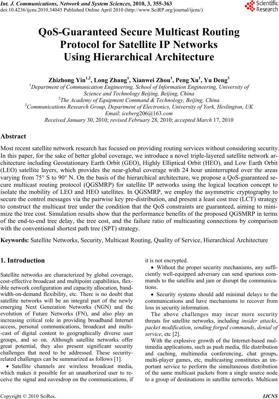 Int. J. Communications, Network and System Sciences, 2010, 3, 355-363 doi:10.4236/ijcns.2010.34045 blished Online April 2010 (http://www.SciRP.org/journal/ijcns/) Copyright © 2010 SciRes. IJCNS Pu QoS-Guaranteed Secure Multicast Routing Protocol for Satellite IP Networks Using Hierarchical Architecture Zhizhong Yin1,2, Long Zhang1, Xianwei Zhou1, Peng Xu1, Yu Deng3 1Department of Communication Engineering, School of Information Engineering, University of Science and Technology Beijing, Beijing, China 2The Academy of Equipment Command & Technology, Beijing, China 3Communications Research Group, Department of Electronics, University of York, Heslington, UK Email: iceberg206@163.com Received January 30, 2010; revised February 28, 2010; accepted March 17, 2010 Abstract Most recent satellite network research has focused on providing routing services without considering security. In this paper, for the sake of better global coverage, we introduce a novel triple-layered satellite network ar- chitecture including Geostationary Earth Orbit (GEO), Highly Elliptical Orbit (HEO), and Low Earth Orbit (LEO) satellite layers, which provides the near-global coverage with 24 hour uninterrupted over the areas varying from 75° S to 90° N. On the basis of the hierarchical architecture, we propose a QoS-guaranteed se- cure multicast routing protocol (QGSMRP) for satellite IP networks using the logical location concept to isolate the mobility of LEO and HEO satellites. In QGSMRP, we employ the asymmetric cryptography to secure the control messages via the pairwise key pre-distribution, and present a least cost tree (LCT) strategy to construct the multicast tree under the condition that the QoS constraints are guaranteed, aiming to mini- mize the tree cost. Simulation results show that the performance benefits of the proposed QGSMRP in terms of the end-to-end tree delay, the tree cost, and the failure ratio of multicasting connections by comparison with the conventional shortest path tree (SPT) strategy. Keywords: Satellite Networks, Security, Multicast Routing, Quality of Service, Hierarchical Architecture 1. Introduction Satellite networks are characterized by global coverage, cost-effective broadcast and multipoint capabilities, flex- ible network configuration and capacity allocation, band- width-on-demand flexibility, etc. There is no doubt that satellite networks will be an integral part of the newly emerging Next Generation Networks (NGN) and the evolution of Future Networks (FN), and also play an increasing critical role in providing broadband Internet access, personal communications, broadcast and multi- -cast of digital content to geographically diverse user groups, and so on. Although satellite networks offer great potential, they also present significant security challenges that need to be addressed. These security- related challenges can be summarized as follows [1]. Satellite channels are wireless broadcast media, which makes it possible for an unauthorized user to re- ceive the signal and eavesdrop on the communications, if it is not encrypted. Without the proper security mechanisms, any suffi- ciently well-equipped adversary can send spurious com- mands to the satellite and jam or disrupt the communica- tions. Security systems should add minimal delays to the communications and have mechanisms to recover from loss in security information. The above challenges may incur more security threats for satellite networks, including insider attacks, packet modification, sending forged commands, denial of service, etc [2]. With the explosive growth of the Internet-based mul- timedia applications, such as push media, file distribution and caching, multimedia conferencing, chat groups, multi-player games, etc, multicasting constitutes an im- portant service to perform the simultaneous distribution of the same multicast packets from a single source node to a group of destinations in satellite networks. Multicast 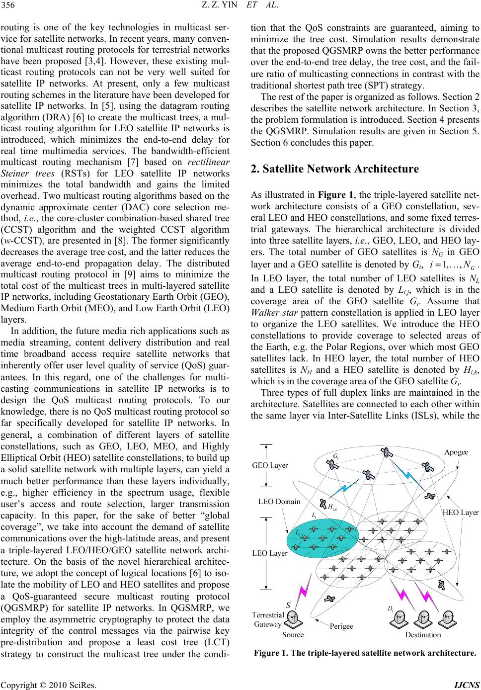 Z. Z. YIN ET AL. 356 routing is one of the key technologies in multicast ser- vice for satellite networks. In recent years, many conven- tional multicast routing protocols for terrestrial networks have been proposed [3,4]. However, these existing mul- ticast routing protocols can not be very well suited for satellite IP networks. At present, only a few multicast routing schemes in the literature have been developed for satellite IP networks. In [5], using the datagram routing algorithm (DRA) [6] to create the multicast trees, a mul- ticast routing algorithm for LEO satellite IP networks is introduced, which minimizes the end-to-end delay for real time multimedia services. The bandwidth-efficient multicast routing mechanism [7] based on rectilinear Steiner trees (RSTs) for LEO satellite IP networks minimizes the total bandwidth and gains the limited overhead. Two multicast routing algorithms based on the dynamic approximate center (DAC) core selection me- thod, i.e., the core-cluster combination-based shared tree (CCST) algorithm and the weighted CCST algorithm (w-CCST), are presented in [8]. The former significantly decreases the average tree cost, and the latter reduces the average end-to-end propagation delay. The distributed multicast routing protocol in [9] aims to minimize the total cost of the multicast trees in multi-layered satellite IP networks, including Geostationary Earth Orbit (GEO), Medium Earth Orbit (MEO), and Low Earth Orbit (LEO) layers. In addition, the future media rich applications such as media streaming, content delivery distribution and real time broadband access require satellite networks that inherently offer user level quality of service (QoS) guar- antees. In this regard, one of the challenges for multi- casting communications in satellite IP networks is to design the QoS multicast routing protocols. To our knowledge, there is no QoS multicast routing protocol so far specifically developed for satellite IP networks. In general, a combination of different layers of satellite constellations, such as GEO, LEO, MEO, and Highly Elliptical Orbit (HEO) satellite constellations, to build up a solid satellite network with multiple layers, can yield a much better performance than these layers individually, e.g., higher efficiency in the spectrum usage, flexible user’s access and route selection, larger transmission capacity. In this paper, for the sake of better “global coverage”, we take into account the demand of satellite communications over the high-latitude areas, and present a triple-layered LEO/HEO/GEO satellite network archi- tecture. On the basis of the novel hierarchical architec- ture, we adopt the concept of logical locations [6] to iso- late the mobility of LEO and HEO satellites and propose a QoS-guaranteed secure multicast routing protocol (QGSMRP) for satellite IP networks. In QGSMRP, we employ the asymmetric cryptography to protect the data integrity of the control messages via the pairwise key pre-distribution and propose a least cost tree (LCT) strategy to construct the multicast tree under the condi- tion that the QoS constraints are guaranteed, aiming to minimize the tree cost. Simulation results demonstrate that the proposed QGSMRP owns the better performance over the end-to-end tree delay, the tree cost, and the fail- ure ratio of multicasting connections in contrast with the traditional shortest path tree (SPT) strategy. The rest of the paper is organized as follows. Section 2 describes the satellite network architecture. In Section 3, the problem formulation is introduced. Section 4 presents the QGSMRP. Simulation results are given in Section 5. Section 6 concludes this paper. 2. Satellite Network Architecture As illustrated in Figure 1, the triple-layered satellite net- work architecture consists of a GEO constellation, sev- eral LEO and HEO constellations, and some fixed terres- trial gateways. The hierarchical architecture is divided into three satellite layers, i.e., GEO, LEO, and HEO lay- ers. The total number of GEO satellites is NG in GEO layer and a GEO satellite is denoted by Gi, 1,, G iN . In LEO layer, the total number of LEO satellites is NL and a LEO satellite is denoted by Li,j, which is in the coverage area of the GEO satellite Gi. Assume that Walker star pattern constellation is applied in LEO layer to organize the LEO satellites. We introduce the HEO constellations to provide coverage to selected areas of the Earth, e.g. the Polar Regions, over which most GEO satellites lack. In HEO layer, the total number of HEO satellites is NH and a HEO satellite is denoted by Hi,k, which is in the coverage area of the GEO satellite Gi. Three types of full duplex links are maintained in the architecture. Satellites are connected to each other within the same layer via Inter-Satellite Links (ISLs), while the i G ,ij L i L ,ik H i D Figure 1. The triple-layered satellite network architecture. Copyright © 2010 SciRes. IJCNS  Z. Z. YIN ET AL. 357 communications between satellites (e.g. GEO and LEO satellites) in different layers is completed via Inter-Or- bital Links (IOLs). Note that communication capabilities from HEO satellites is only provided when HEO satel- lites are moving very slowly relative to the globe while in the vicinity of apogee. For that reason, assume that the communications between GEO satellites and HEO satel- lites is accomplished via IOLs when HEO satellites are moving near apogee, while the communications among HEO satellites cannot be maintained through ISLs in the architecture. The terrestrial gateways are directly con- nected to LEO and GEO satellites via User Data Links (UDLs) and assumed to be the sources and destinations of multicasting communications. Considering the logical locations of satellites, we in- troduce the satellite domains to organize satellites in a hierarchical manner in order to isolate the mobility of satellites from upper layer, i.e., GEO layer. A LEO satel- lite domain Li is the set of logical locations of LEO satel- lites that are within the coverage of a GEO satellite Gi. ISLs in LEO layer can be categorized into two types, i.e., intra-domain ISLs and inter-domain ISLs. Note that the LEO satellites are connected to their adjacent neighbors over the grid points in the same layer via intra-domain ISLs. Here, , {1,,( iij i LLj L)}, where () is a size function that generates the total number of satellites in a satellite domain. Similarly, a HEO satellite domain Hi is the set of logical locations of HEO satellites that are within the coverage of a GEO satellite Gi, and , {1,,( iik i HHk H)}. Assume that half of the HEO satellites within a HEO constellation in the same orbit have IOLs with a GEO satellite at time instant and different GEO satellites may own the same HEO satellite domains. We give an example to illustrate the HEO do- main in the architecture. As shown in Figure 2, a HEO constellation owns 6 satellites and a HEO domain con- tains 3 satellites. Figure 2. A HEO domain for example. 3. Problem Formulation The topology of satellite network based on our architec- ture is modeled as a connected directed graph (, )GVE , where V is the set of nodes representing satellites and terrestrial gateways in our architecture and is the set of links connecting the nodes, i.e., ISLs, IOLs and UDLs. EVV Definition 1. Let a terrestrial gateway denote a source, and other terrestrial gateways constitute a set of destinations, i.e., , called a multicast group. A multicast tree SV {}DV S (, TT TV )E , for and , is a subtree of the graph rooted from S, which contains all of the nodes of D and an arbi- trary subset of T V (, )GV E V T EE VD . Definition 2. The link state of a link l consists of delay and available bandwidth , for , where ()l () ()llE :lE R ()l and are delay function and available bandwidth function, respectively. Note that the delay of a link l contains three delay compo- nents: 1) radio propagation delay, 2) queuing delay, and 3) protocol processing delay. ():lE R Definition 3. The available path bandwidth of a path P is the minimum bandwidth of the links along the path, i.e., ()BP () argmin{(),1, ,()} ii BPl lPiP (1) where () is a function that returns the number of links in the path P. Definition 4. The available tree bandwidth of a multicast tree T is the minimum bandwidth of the links in the multicast tree, i.e., ()BT () argmin{(),1, ,()} ii BTllT iT (2) where () is a function that returns the number of links in the tree T. Definition 5. The path delay of a path P is the sum of the delay of the links on the path, i.e ., ()DP () 1 () () P i i DP l (3) Definition 6. The tree delay of a multicast tree T is the end-to-end maximum delay of the paths from source S to the destinations of D on the multicast tree, i.e., ()DT ()arg max{()1,,} i SD DTDP iD (4) where denotes a path from source S to destina- tion , and i SD P i DD denotes the number of destinations. C opyright © 2010 SciRes. IJCNS  Z. Z. YIN ET AL. 358 Definition 7. The path cost of a path P is de- fined as the product of available path bandwidth and path delay of path P, i.e., ()CP ()() ()CP BPDP (5) Definition 8. The least cost path from node A to node B is defined as a path that satisfies AB P ()argmin{()1,,() i AB ABAB CPCP iP } (6) where denotes a feasible path from node A to node B, and is a function that returns the num- ber of feasible paths from node A to node B. AB P () Definition 9. The tree cost of a multicast tree T is defined as the product of the available tree band- width and the tree delay of the multicast tree T, i.e., ()CT () () ()CT BT DT (7) Our problem is: given a satellite network (, )GVE , a source S, a multicast group D, a delay bound , and a bandwidth bound , to construct a multicast tree which spans S and D such that the tree cost defined in (7) is minimized under the condition that the available tree bandwidth and tree delay of the multicast tree T satisfy the required QoS constraints, namely, 1) delay constraint: , and 2) bandwidth con- straint: . (, ) TT TVE ()BT ()DT 4. The Proposed Protocol Our proposed QoS-guaranteed secure multicast routing protocol (QGSMRP) is composed of four processes, i.e., link state report, route discovery and reply, route main- tenance, and multicast tree creation. In QGSMRP, we assume that every node and its neighbor node in the sat- ellite network mutually have the pairwise keys, i.e., public keys and private keys, preloaded by key pre-distribution mechanism. We also assume that every node in the satellite network has unique node address. Table 1 provides the notation description which will be used for cryptographic operations in the paper. (, )GVE 4.1. Link State Report The link state report process is initiated when a source receives a QoS request for setting up a multicasting con- nection with a multicast group D and the delay bound and bandwidth bound . The source initially creates a report request (REPORT_REQ) message and then transmits it to a GEO satellite via a UDL. When receiv- ing the REPORT_REQ, the GEO satellite follows the steps below to complete the link state report process. Table 1. Notation description. Notations Descriptions A The public key held by node A A The private key held by node A Timestamp {} A M Encryption of message M with key A [] A M Decryption of message M with key A SRid STATE_REPORT ID RRQid RREQ ID RRPid RREP ID JRQid Join_REQ ID JRPid Join_REP ID JNid Join_NAK ID 1) Link State Report Request Step 1: The GEO satellite sends the REPORT_REQ to other adjacent GEO satellites via ISLs. Step 2: When the REPORT_REQ are received by all the GEO satellites in GEO layer, each GEO satellite sends the REPORT_REQ to the LEO and HEO satellites within its covered LEO and HEO domain through IOLs. Step 3: In LEO layer, LEO satellite floods the RE- PORT_REQ to other LEO satellites within the same do- main via intra-domain ISLs and across different domains via inter-domain ISLs. Step 4: The members of the multicast group D receive the REPORT_REQ from the GEO and LEO satellites via UDLs. After all the nodes in the satellite network acquire the REPORT_REQ, the link state interaction process is initi- ated. 2) Link State Interaction Step 1: The member of the multicast group D, i DD , sends a state report (STATE_REPORT) message to the GEO and LEO satellites via the reverse UDLs. The STATE_REPORT is constructed as follows: <{SRid, Node Address, Downstream Node Address, } i D , Available Bandwidth, Delay> The pair <Node Address, SRid> uniquely identifies the STATE_REPORT. The SRid is monotonically increasing when a node issues a new STATE_REPORT to its downstream node and can be used to check the duplicate copies of an old STATE_REPORT for the downstream node. The destination encrypts the message {SRid, Node Address, Downstream Node Address, } with its private key i D i D D K . The Available Bandwidth and Delay record the available bandwidth and the delay be- tween a node and its downstream node over the corre- sponding link. When a GEO satellite (or a LEO satellite) Copyright © 2010 SciRes. IJCNS 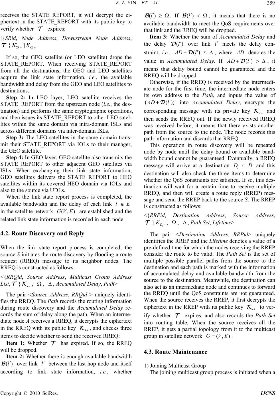 Z. Z. YIN ET AL. 359 receives the STATE_REPORT, it will decrypt the ci- phertext in the STATE_REPORT with its public key to verify whether expires: [{SRid, Node Address, Downstream Node Address, } ] i D i G K If so, the GEO satellite (or LEO satellite) drops the STATE_REPORT. When receiving STATE_REPORT from all the destinations, the GEO and LEO satellites acquire the link state information, i.e., the available bandwidth and delay from the GEO and LEO satellites to destinations. Step 2: In LEO layer, LEO satellite receives the STATE_REPORT from the upstream node (i.e., the des- tination) and performs the same cryptographic operations, and then issues its STATE_REPORT to other LEO satel- lites within the same domain via intra-domain ISLs and across different domains via inter-domain ISLs. Step 3: The LEO satellites in the same domain trans- mit their STATE_REPORT via IOLs to their manager, the GEO satellite. Step 4: In GEO layer, GEO satellite also transmits the STATE_REPORT to other adjacent GEO satellites via ISLs. When exchanging their link state information, GEO satellites delivers the STATE_REPORT to HEO satellites within its covered HEO domain via IOLs and also to the source via UDLs. When the link state report process is completed, the available bandwidth and the delay of each link lE in the satellite network are established and the related link state information is recorded in each node. (, )GV E 4.2. Route Discovery and Reply When the link state report process is completed, the source S initiates the route discovery by flooding a route request (RREQ) message to its neighbor nodes. The RREQ is constructed as follows: <{RRQid, Source Address, Multicast Group Address List,}, , , Accumulated Delay, Path> S The pair <Source Address, RRQid > uniquely identi- fies the RREQ. The Path records the routing information during route discovery and the Accumulated Delay re- cords the sum of delay along the path. When an interme- diate node A receives a RREQ, it decrypts the ciphertext in the RREQ with its public key , and checks three items to decide whether to send the received RREQ: A Item 1: Whether has expired. If so, the RREQ will be dropped. Item 2: Whether there is enough available bandwidth over link l between the last hop node and itself according to link state information, i.e., whether ()l () l . If () l ) , it means that there is no available bandwidth to meet the QoS requirements over that link and the RREQ will be dropped. Item 3: Whether the sum of Accumulated Delay and the delay (l AD over link meets the delay con- straint, i.e., l () l , where A D denotes the value in Accumulated Delay. If () AD l , it means that delay bound cannot be guaranteed and the RREQ will be dropped. Otherwise, if the RREQ is received by the intermedi- ate node for the first time, the intermediate node enters its own address to the Path, and inputs the value of (()) A Dl into Accumulated Delay, encrypts the corresponding message with its private key A and then sends the RREQ out. If the newly received RREQ was received before, it means that there exists another path from the source to the node. The node records this path information and discards that RREQ. This operation in route discovery will be repeated node by node until the delay bound or available band- width bound cannot be guaranteed. Eventually, a RREQ message will arrive at a destination and this destination will also check the three items to determine whether the QoS constraints are satisfied. If so, this des- tination will wait for a certain time to receive multiple RREQ, and then will create a route reply (RREP) mes- sage and send the RREP back to the source S. The RREP is constructed as follows: i DD <{RRPid, Destination Address, Source Address, } i D K , , , Path Set, Lifetime> The pair <Destination Address, RRPid> uniquely identifies the RREP and the Lifetime denotes a value of a pre-defined time for which the nodes receiving the RREP consider the route to be valid. The Path Set is the set of multiple possible parallel paths from the source to the destination and each path is marked with the information of accumulated delay and available bandwidth from the source to the destination. Meanwhile, the destination can also act as an intermediate node and continues to forward the RREQ until the QoS constraints are not guaranteed. When the source receives the RREP, it first decrypts the ciphertext in the RREP with its public key S to ver- ify whether expires, and also records the Path Set into routing table. When the source receives all the RREP, it gets a partial topology from it to the multicast group in satellite network . (, )GVE 4.3. Route Maintenance 1) Joining Multicast Group The joining multicast group process is initiated when a C opyright © 2010 SciRes. IJCNS  Z. Z. YIN ET AL. 360 new terrestrial gateway wants to join a multicast group D. The new terrestrial gateway firstly creates a STATE_REPORT and then sends the STATE_REPORT to the GEO and LEO satellites via UDLs. Through link state interaction, the nodes with the corresponding links acquire the link state information. Then the new terres- trial gateway broadcasts a join request (JOIN_REQ) message which is constructed as follows: new D <{JRQid, Terrestrial Gateway Address, } new D , Path, Accumulated Delay> The pair <Terrestrial Gateway Address, JRQid> uniquely identifies the JOIN_REQ. When an intermedi- ate node receives a JOIN_REQ, it checks the three items to decide whether to reflood the received JOIN_REQ. The new gateway will send multiple JOIN_REQ out within a pre-defined time until they arrive at a desitination . The destination firstly waits for a certain time to receive multiple JOIN_REQ. Secondly, according to the Path, it will check the three items to determine whether the QoS constraints are satisfied. If so, the destination creates a join reply (JOIN_REP) message and sends it back to the new gateway. Note that this des- tination serves as a forwarding node and the source does not know the information about this new gateway. The JOIN_REP is constructed as follows: i DD <{JRPid, Destination Address, Terrestrial Gateway Ad- dress, } i D K , , > The pair <Destination Address, JRPid> uniquely iden- tifies the JOIN_REP. After a pre-defined time, the new gateway does not receive any more JOIN_REP and the joining multicast group process terminates. 2) Leaving Multicast Group The leaving multicast group process is initiated when a destination wants to leave a multicast group D. The destination firstly sends out multiple join negative acknowledgement (JOIN_NAK) messages to its neigh- bors and then deletes all the routing information of the neighbors. The JOIN_NAK is constructed as follows: leave D <{JNid, Terrestrial Gateway Address, } leave D K , Path> The pair <Terrestrial Gateway Address, JNid> uniq- uely identifies the JOIN_NAK. When receiving a JOIN_ NAK, a neighbor checks whether it has an upstream node or a downstream node. If so, the neighbor prunes the link from this destination and deletes the routing in- formation of this destination, and then transmits the JOIN_NAK to notify that this destination has been leav- ing the multicast group. Otherwise, the neighbor will check whether it is a member of multicast group. If so, the neighbor just prunes the link from this destination. Otherwise, the neighbor becomes a non-forwarding node and withdraws from the QoS multicasting communica- tions. 4.4. Multicast Tree Creation The multicast tree creation process is activated by the source at the end of the route discovery and reply process. As mentioned previously, the source has maintained multiple parallel paths from itself to several destinations in multicast group. Therefore, the main goal of the source is to select one of the parallel paths to set up a multicasting connection, and then proceed to create a multicast tree. In this paper, we present a least cost tree (LCT) strategy to construct the multicast tree under the condition that the QoS requirements are guaranteed. The basic idea of the LCT strategy works as follows. Assume that the Path Set from a destination i D1, ,iD, is denoted by . When receiving a RREP from a desti- nation , the source gets the information of accumu- lated delay and available bandwidth from the source to this destination along a path , i PS i D ,ij P1, ,i jPS, i.e., path delay and available path bandwidth . Therefore, the source can compute the path cost , () ij ) DP ,, ( ij BP , ( ij BP () ij CP ) , () ij DP ) for the path , and then compare to select a path with the least path cost, i.e., ,ij P , ( ij CP ,ij P ,, ( )argmin{( )1,,,1,,} ij iji CPCPiD jPS (9) After a pre-defined time, the source gains all the in- formation about the paths with least path cost from itself to each destination in the multicast group D. Afterwards, the source follows the steps below to create a multicast tree. When the multicast tree is built up, the multicast session begins. Step 1: Construct two node sets {} K SD and 0 {} H S . Step 2: Start with a subtree , where 000 (, )TVE 0{}VS and 0 E . Step 3: For 1,,D , the source finds a node in 1 K H , i.e., a destination , such that the path cost from the source to is minimum among all the paths with the least path cost, i.e., i D i D , argmin{( )1,, ,1,,} iij DCPiDj i PS (10) Construct the subtree by adding the path (,)TVE ,ij P between the source and to T i D , i.e., set 1, {nodes in} ij PVV and 1, s in} ij P{linkEE 1{} i . Meanwhile, set H HD . Copyright © 2010 SciRes. IJCNS  Z. Z. YIN ET AL. Copyright © 2010 SciRes. IJCNS 361 5. Performance Evaluation Table 2. Parameters for triple-layered satellite networks. Parameters LEO Layer HEO Layer GEO Layer Type of orbit LEO Recursive orbit HEO Recursive orbit GEO Altitude 1262 km 27000 km(A) 800 km(P) 35786 km Orbital period 6628 s 8 h 24 h Number of satellites32 4 4 Number of orbital planes 4 2 1 Orbit inclination angle48° 63.4° — Minimum elevation angle — 10° 5° Constellation type Walker star Draim — Semi-major axis — 20278 km — Eccentricity — 0.646 — Argument of perigee— 270° — Phase factor 1 — — Ascending node longitude — 90° E — In this section, we evaluate the performance of QGSM- RP by comparing it with the conventional shortest path tree (SPT) strategy [10] via computer simulations. In our empirical study, three metrics are considered in the per- formance evaluations, i.e., 1) the end-to-end tree delay, 2) the tree cost, and 3) the failure ratio of multicasting con- nections. In our simulations, the parameters of the triple-layer satellite network are described in Table 2. The perform- ance of coverage from the triple-layer satellite network is illustrated in Figure 3. According to Figure 3, triple- layered satellite network can offer coverage over the areas varying from 75° S to 90° N with 24 hour uninter- rupted. We use the non-uniform distribution [9] to deter- mine the positions of the terrestrial gateways, including the source and the multicast group. Moreover, we assume that the capacity of all ISLs, IOLs, and UDLs are set to 800 Mb/s, each outgoing link has a buffer space of 20 MB, and the delay bound and bandwidth bound are set to ms and Mb/s, respectively. 450 256 Figure 4 and Figure 5 illustrate the performance of the end-to-end tree delay of the proposed QGSMRP and the SPT strategy, respectively. The size of multicast group is set to 50. We can observe that with the growth of the simulation time, the variation of the end-to-end tree delay of the proposed QGSMRP and the SPT strat- egy is almost uniform with the range of 0.1 s to 0.5 s. Furthermore, the end-to-end tree delay changes quickly and obviously as the simulation time increases. Figure 3. Near-global coverage from the satellite network using the proposed triple-layered LEO/HEO/GEO architecture.  Z. Z. YIN ET AL. 362 End-to-End Tree Delay (s) Simulation Time (s) 0 100 200 300 400 500 600 700 800 900 QGSMRP 0.8 0.7 0.6 0.5 0.4 0.3 0.2 0.1 0 Figure 4. The end-to-end tree delay of the proposed QGS- MRP. End-to-End Tree Delay (s) Simulation Time (s) 0 100 200 300 400 500 600 700 800 900 SPT 0.8 0.7 0.6 0.5 0.4 0.3 0.2 0.1 0 Figure 5. The end-to-end tree delay of the SPT strategy. Figure 6 shows the comparison of the end-to-end tree delay versus the multicast group size between the SPT and the proposed QGSMRP. It can be easily seen that the end-to-end tree delay of the proposed QGSMRP is much lower than that of the SPT strategy with the increase of the size of the multicast group. Figure 7 compares the performance of the tree cost versus the multicast group size between the SPT and the proposed QGSMRP. We can obviously see that as the multicast group size grows, the tree cost of the proposed QGSMRP is much smaller than that of the SPT strategy. This can be explained by the fact that the proposed QGSMRP focuses on the opti- mization of the tree cost during the process of the route discovery and reply, whereas the main target of the SPT strategy is to bring the better performance of the path delay in the multicast tree without taking into account the available bandwidth in the process of the multicast tree construction. End-to-End Tree Delay (s) Multicast Group Size 5 10 15 20 25 30 SPT QGSMRP 0.6 0.5 0.4 0.3 0.2 0.1 0 Figure 6. Comparison of the end-to-end tree delay between the SPT strategy and the proposed QGSMRP. Tree Cost (10 ^ 3) Multicast Group Size 5 10 15 20 25 30 SPT QGSMRP 140 120 100 80 60 40 20 0 Figure 7. Comparison of the tree cost between the SPT strategy and the proposed QGSMRP. Figure 8 demonstrates the comparison of the failure ratio of multicasting connections between the SPT strat- egy and the proposed QGSMRP. It can be observed from Figure 8 that the failure ratio of multicasting connec- tions of the proposed QGSMRP is smaller than that of the SPT strategy with the range of 15 to 30 of the multi- cast group size, which indicates that the success ratio of the QoS multicasting requests of the proposed QGSMRP is superior to that of the SPT strategy with the growth of the multicast group size. For that reason, the proposed QGSMRP can easily establish the QoS multicasting connections when the scale of the network is large, i.e., a large quantity of the terrestrial gateways. However, the failure ratio of multicasting connections of the SPT strategy is better than that of the proposed QGSMRP in the range of 5 to 10 of the size of the multicast group. We can also observe that the failure ratio of multicasting connections of both of the multicast routing strategies are represented as a gradual increasing trend. Copyright © 2010 SciRes. IJCNS  Z. Z. YIN ET AL. 363 Failure Ratio Multicast Group Size 5 10 15 20 25 30 SPT QGSMRP 0.2 0.15 0.1 0.05 0 Figure 8. Comparison of the failure ratio of multicasting connections between the SPT strategy and the proposed QGSMRP. 6. Conclusions In this paper, considering the difficulty to provide the coverage over the special regions or the areas of high latitudes by the existing hierarchical satellite networks, we introduce a novel triple-layered LEO/HEO/GEO sat- ellite network architecture containing LEO, HEO, and GEO satellite layers, which yields the near-global cov- erage with 24 hour uninterrupted over the areas varying from 75° S to 90° N. On the basis of the novel hierarchi- cal architecture, we propose a QoS-guaranteed secure multicast routing protocol (QGSMRP) for satellite IP networks using the concept of logical locations to isolate the mobility of LEO and HEO satellites. In QGSMRP, through the pairwise key pre-distribution, we employ the asymmetric cryptography to secure the data integrity of the control messages, and present a least cost tree (LCT) strategy to construct the multicast tree under the condi- tion that the QoS constraints are guaranteed, aiming to minimize the tree cost. Simulation results demonstrate that the proposed QGSMRP owns the better performance including the end-to-end tree delay, the tree cost, and the failure ratio of multicasting connections by comparison with the conventional shortest path tree (SPT) strategy. 7. Acknowledgements This work is supported in part by the National Natural Science Foundation of China under Grant No. 60903004, the National High-Tech Research and Development Plan of China under Grant No. 2009AA01Z209, and the Na- tional Key Technology Research and Development Pro- gram of China under Grant No. 2007BAB18B03. 8. References [1] R. Chowdhury, J. S. Baras, M. Hadjitheodosiou and S. Papademetriou, “Security Issues in Hybrid Networks with a Satellite Component,” IEEE Wireless Communications, Vol. 12, No. 6, December 2005, pp. 50-61. [2] N. Boudriga, “Security of Mobile Communications,” Boca Raton, Auerbach Publications, FL, 2009, pp. 474-479. [3] L. H. Sahasrabuddhe and B. Mukherjee, “Multicast Rout- Ing Algorithms and Protocols: A Tutorial,” IEEE Net- work, Vol. 14, No. 1, January/February 2000, pp. 90-102. [4] U. Varshney, “Multicast over Wireless Networks,” Communications of the ACM, Vol. 45, No. 12, December 2002, pp. 31-37. [5] E. Ekici, I. F. Akyildiz and M. D. Bender, “A Multicast Routing Algorithm for LEO Satellite IP Networks,” IEEE/ACM Transactions on Networking, Vol. 10, No. 2, April 2002, pp. 183-192. [6] E. Ekici, I. F. Akyildiz and M. D. Bender, “A Distributed Routing Algorithm for Datagram Traffic in LEO Satellite Networks,” IEEE/ACM Transactions on Networking, Vol. 9, No. 2, April 2001, pp. 137-147. [7] D. Yang and W. Liao, “On Multicast Routing Using Rect-Ilinear Steiner Trees for LEO Satellite Networks,” IEEE Transactions on Vehicular Technology, Vol. 57, No. 4, July 2008, pp. 2560-2569. [8] L. Chen, J. Zhang and K. Liu, “Core-Based Shared Tree Multicast Routing Algorithms for LEO Satellite IP Netw- Orks,” Chinese Journal of Aeronautics, Vol. 20, No. 4, August 2007, pp. 353-361. [9] I. F. Akyildiz, E. Ekici and G. Yue, “A Distributed Mul- Ticast Routing Scheme for Multi-Layered Satellite IP Networks,” Wireless Networks, Vol. 9, No. 5, September 2003, pp. 535-544. [10] J. A. Bondy and U. S. R. Murty, “Graph Theory with Applications,” The Macmillan Press, Great Britain, 1976, pp. 15-20. C opyright © 2010 SciRes. IJCNS |