Engineering
Vol. 3 No. 7 (2011) , Article ID: 6156 , 9 pages DOI:10.4236/eng.2011.37095
Dynamic Response Analysis of Beams with Oblique Collision
College of Civil Engineering & Architecture, Zhejiang University of Technology, Hangzhou, China
E-mail: pjp@zjut.edu.cn
Received February 26, 2011; revised June 12, 2011; accepted June 20, 2011
Keywords: Dynamic Contact, Beam, Oblique Collision, Time-Variant Matrices
ABSTRACT
Adopting a dynamic contact numerical method, some problems such as the central colli-sion, transverse collision and oblique collision between two beams are researched. Numeri-cal expressions for these cases are deduced. Using a self-developed finite element program some examples are computed, and compared with the analytical solution of the central collision, this numerical algorithm is proved to be reliable. For the other numerical results that have no analytical solution to be used to compare with, they are also reason-able through the theoretical analysis. For the transverse and oblique collision, the ideal results can be obtained by using a smaller time step.
1. Introduction
During these years, many engineers and theoretical researchers have done a great quantity of work for the elastic collisions between structures. Lauren [1] studied on the problem of contact and impact with and without friction by using an algorithm of energy-momentum, giving an unabridged numerical solution of the central collision between rods. D. Baraff [2] investigated the problem of rigid-body simulation with large numbers of contact points, discussing how to handle the contact force of system of rigid bodies with and without Coulomb friction and presenting an approximate method on handling the static and dynamic friction. Liu Shu [3] presented a dynamic contact numerical method and the equations of velocity and displacement were deduced. Ruan and Yu [4] studied the collision between two deformable structures using a simple mass-spring system. Literature [5] proposed several local contact models for a collision between a beam with cylindrical cross-section and a simply supported beam with rectangular cross-section, comparing the results obtained experimentally and suggesting some local contact models. Taking the classical St. Venant’s solution as reference, Escalona [6] developed a new numerical method based on the theoretical solution to identify the elastic wave, stress as well as velocity yielded on the contact surface, which shows an excellent agreement with thoretical results. Pashah etc. [7] investigated the structural response for a low velocity impact using an impact models, pointing out that the selection of the impact model depends on the structural response, finding out there were more than 2 collisions happened between a sphere and a simple-supported beam. Liu [8] presented a multiple contact impact separation method to solve the collision between a free-free beam and a simple-supported beam, but the free-free beam is always in a horizontal state during the collision process. T. Narabayashi [9] employed an analysis method to solve the collision between bar and beam, in which the impact force was assumed as an exponential function and satisfied the condition of continuity of the displacement. Ruan [10] experimentally indicated that most of the plastic deformation occurred in their mid-span during the collision between a flying free-free beam and a simply supported beam, obtaining energy dissipation ratio which had a good agreement with theoretical prediction. From the literatures published these years, researches on the numerical computation for the oblique collision between two beams were not found. Based on the dynamic contact theory, expansion form of time-integration expression is deduced, and some examples are calculated by means of a self-developed finite element program to prove the numerical expression is reliable.
2. Numerical Expression of the Oblique Collision
2.1. Time-Integration Expression for Dynamic Contact Problem
Collision between two beams is the dynamic contact problem that needs to consider the surface contact of the beam, requiring to meeting the boundary condition and initial condition besides the contact condition on the contact surface. Handling the dynamic contact problem, the equilibrium conditions of the contact force and the compatibility conditions of the displacement on the contact surfaces must be considered at the same time. The contact forces R and τ on the contact surfaces are equal and opposite interaction forces, respectively, shown in Figure 1.
If a contact happened, the conditions on the normal direction can be described as
 (1)
(1)
where  and
and  are the displacements at the next time-step without the collision force. Displacement coordination conditions for the non-penetration collision in the normal and tangential direction can be stated as
 (2)
(2)
where ,
,  and m is the amount of contact nodes.
Based on Newmark-β method, equations of the velocity and displacement could be written as follows in timedomain integration [3]
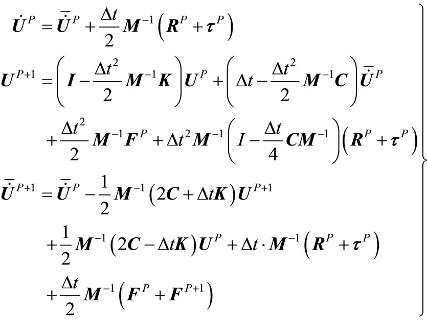 (3)
(3)
The second equation of Equation (3) can more conveniently and clearly be written as
 (4)
(4)
where
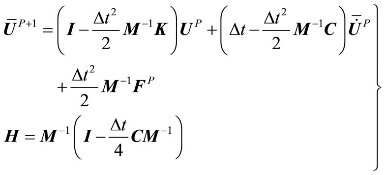 (5)
(5)
In Equation (4),  is the displacement at the next time step without the collision force. In other words, the total displacement at the next step consists of two parts, one is the displacement caused by the equivalent load and the inertia of the structure, the other is caused by the collision force.
Collision force plays a core role in the collision problem using the dynamic contact method. So the first step is to judge whether the contact has happened between structures. Then the collision force can be calculated by the displacement coordination condition using Equation (2). With the collision force solved from above, the displacement and velocity are easily to be obtained.
2.2. Expansion Forms of Time-Integration Expression
As shown in Figure 2, beam A moves to beam B with a velocity v0 in axial direction. It is assumed that the contact node on beam A is node i and that on beam B is node j. It is clear that the relative velocity and collision force in tangential direction will not exist.

Figure 1. Force and relative displacement on contact surface.

Figure 2. Central collision of beams.
According to Equation (1), if the displacements of node i and node j is met the condition
 (6)
(6)
then the contact has happened between beam A and beam B, where  and
and  are the displacements of the contact nodes in axial direction at the next time-step without the collision force, and D0 is the distance between node i and node j in the axial direction at initial time.
To obtain the value of collision force R, for beam A, Equation (4) can be written as follow
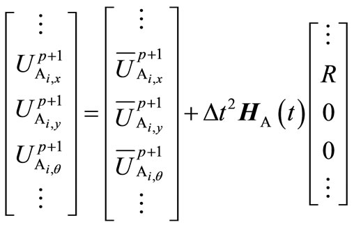 (7)
(7)
And for beam B, it can be written as follow
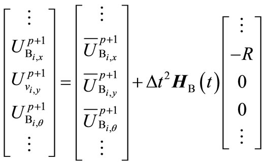 (8)
(8)
Substituting Equation (7) and Equation (8) into the first equation of Equation (2) leads to the equation in which includes the collision force R. And solving the equation just made, we can calculate R. Then other variables such as the velocity, displacement can be obtained at the next time step.
A sketch of the transverse collision between beams is shown in Figure 3. The node i on beam A with velocity v0 is impacted to the node j on beam B. It is easily known that the tangential collision force equal to zero due to no the relative velocity in that direction.
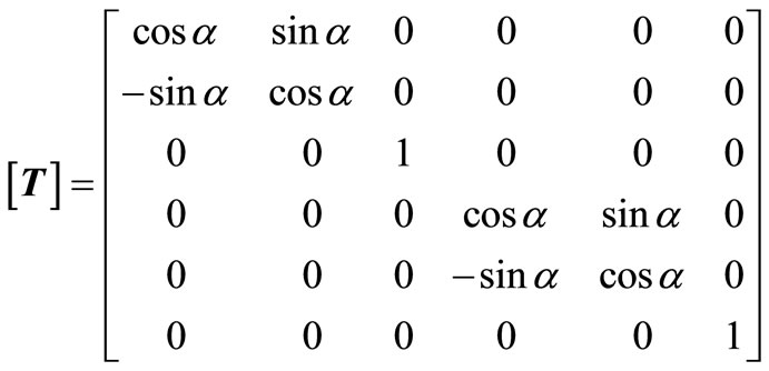
Different from the central collision, before added to the general matrix of beam, the stiffness and mass matrix should be transferred by a transformation matrix T. Specific operation can be easily found in books on the FEM. Transformation matrix T can be denoted as
 (9)
(9)
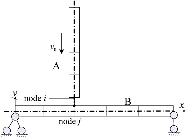
Figure 3. Node-to-node transverse collision between beams.
where α is the angle between the axial direction of beam A and the horizon. Angle is α = 90˚ when the transverse collision happened.
According to the Equation (1), if the displacements of node i and node j is met the condition
 (10)
(10)
then the contact has happened between beam A and beam B. Where  and
and  are the displacements of the contact nodes in y direction at the next time-step without the collision force.
It is assumed that all variables used bellow are transferred by T. Using the Equation (4), for beam A, it can be written as follow
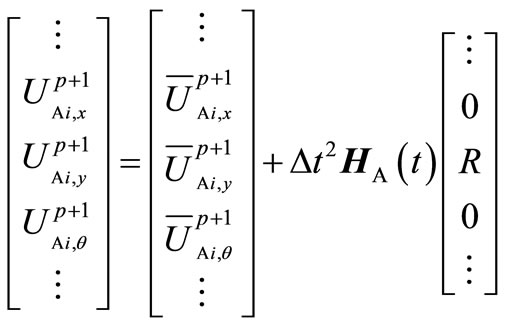 (11)
(11)
And for beam B, it can be written as follow
 (12)
(12)
Then like the way did as the central collision, we can obtain the key variable R, with which all variables will be solved.
By now we’ve just analyzed a node-to-node collision which is the basement of the more complicated collision. Then a simple model of node-to-surface collision between beams is shown in Figure 4. Beam A, with velocity

Figure 4. Node-to-surface transverse collision of beams.
v0 in y direction, moves to the point (not the node) in jth element of beam B. The horizontal distance between axis of beam A and node j as well as node j + 1 are x1 and x2, respectively. The length of a contact element of beam B is le.
Linear interpolation is used to get the variables at contact point from the variables on the nodes located in the two sides of the contact element. Take the collision force as example, the collision force of beam B is distributed to the node j and node j + 1 by the static equivalent principle.
It is easily known that the collision force in x direction equal to zero due to being no a relative velocity in x direction.
The first step is to judge whether the contact has happened between beams. According to the Equation (1), if the displacements of node i and node j is met the condition
 (13)
(13)
then the contact has happened between beam A and beam B, where  and
and  are the displacements of the contact points in y direction at the next time-step without the collision force, and the subscript je denotes the contact point of element.
It is assumed that all variables used bellow are transferred by T. To obtain the collision force, for beam A Equation (4) can be written as follow
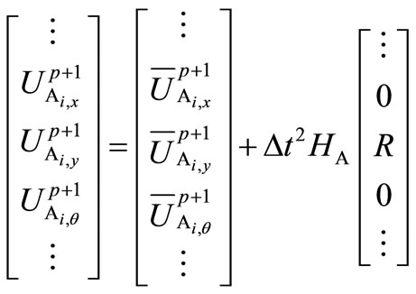 (14)
(14)
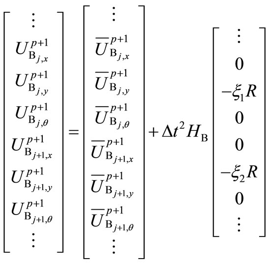
And for beam B it can be written as follow
 (15)
(15)
where ξ1 = x2/le, ξ2 = x1/le, H(t) can be written as (16).
An equation of displacement coordination conditions is used to obtain the collision force. Combined Equation (14), Equation (15) and Equation (16), it may be written as follows
 (17)
(17)
Then depending on the linear interpolation, we can get the vertical displacement of the contact point as follow
 (18)
(18)
In above expression the subscript je denotes the contact point of beam B.
According to the displacement coordination in the normal direction, i.e. the first equation of Equation (2), it

may be written as follow
 (19)
(19)
Substituting Equation (17) and Equation (18) into Equation (19), we can get
 (20)
(20)
As shown in Figure 5, Beam A, with velocity v0 and rake angle α, moves to the point (not the node) in jth element of beam B, it is a general position for two beams. For example, when 0 ≤ a ≤ l2, b ≥ 0, initial angle α0 = 90˚, it is the case of the transverse collision.
When the collision happened, beam A can’t be kept moving forward as before any more. Node i (a contact node on beam A) may move in x direction, i.e., the endpoint of beam A may slide along the beam B if the friction is not big enough. When a contact slide happens along the beam B, it must meet the below inequality
 (21)
(21)
where μs is the coefficient of friction, τ is the tangential collision force, and R is the normal collision force.
Beam A will rotate when the collision happened between beams, because one side of beam A (contact node i) is hindered while the other side is still free. Thus the angle between the axial direction of beam A and horizon will change with time, denoted as α(t). So the mass and stiffness matrix will also change with time relate to the angle α(t), denoted as MA(t) and KA(t), respectively. Therefore, the mass and stiffness matrix should be calculated at each time step. Correspondingly the transformation matrix T is modified into a more exact expression as Equation (22).
Then we can get the exact mass and stiffness matrix with the help of T(t) at any time step.
Node-to-surface contact form is the main form for the oblique collision between beams owing to that the node-to-node model is just a special model during the process of a dynamic contact. So the node-to-surface dynamic contact analysis method should be applied for the oblique collision. The tangential collision force does not equal to zero due to being the relative velocity in the tangential direction, denoted as τ. Like handling the normal collision force, force τ is also distributed among the nodes located in the contact element of beam B by the static equivalent principle.
The first step is to judge whether the contact has happened between beams. According to the Equation (1), if the displacements of node i and j is met the condition
 (23)
(23)
then the contact has happened between beam A and beam B, where  and
and  are the displacements of the contact points at the next time-step without the collision force, and the subscript je denotes the contact point in element.
It is assumed that all variables used bellow are transferred by T(t). For beam A, Equation (4) can be written as follow
 (24)
(24)
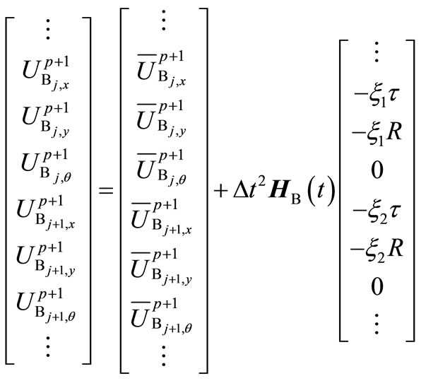
And for beam B it can be written as follow
 (25)
(25)
where ξ1 = x2/le, ξ2 = x1/le, H(t) is the same as that given by Equation (16). Unfold Equations (24) and (25) to form the new equations including the collision force. In y

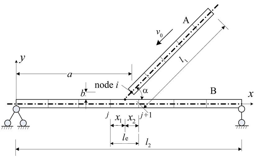
Figure 5. Node-to-surface oblique collision of beams.
direction the equation can be written as follow
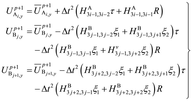 (26)
(26)
Using a linear interpolation method we can get the displacement at the contact point of beam B in y direction, which is written as follow
 (27)
(27)
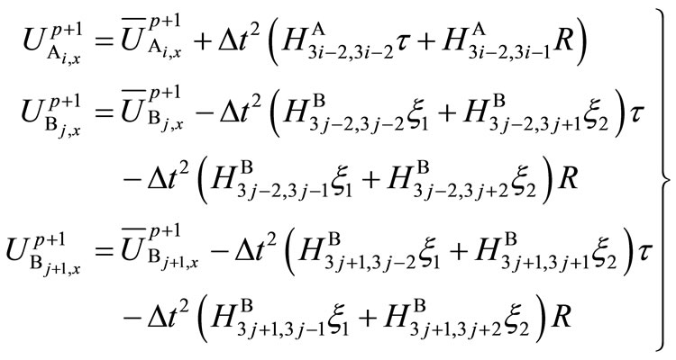
In x direction the equation can be written as follow
 (28)
(28)
Using the linear interpolation method we can also get the displacement at the contact point of beam B in x direction, which is written as follow
 (29)
(29)
There are two variables R and τ, so two equations are needed for solution. Substituting Equations (26)-(29) into the displacement coordination Equations (2) in both normal and tangential direction, we can obtain two equations including R and τ written as below
 (30)
(30)
 (31)
(31)
In formula (31) the subscript je denotes the contact point in beam B.
Then combined with Equation (3), the velocity and displacement can be easily obtained after solving Equations (30) and (31) during the time domain.
3. Numerical Examples
3.1. Central Collision of Beam
As shown in Figure 2, beam A moves to beam B with velocity v0 = 1 m/s. Beam B is static locating 0.5 m on the right of beam A. Length of both beams is 10 m, and the area of section of beams is 0.4 m2. Material constant: Young’s modulus is E = 100 N/m2, the density of beams is ρ = 1 kg/m3. Both beams are divided into 10 elements, i.e. the length of the element is 1m. The time step is Δt = 0.01s.
By numerical calculation using dynamic contact method, the collision force, displacement and velocity results of the contact node i and j are shown, in Figures 6-8, respectively.
It is shown in the Figures 6-8 that this numerical algorithm is proved to be reliable compared to the analytical solution. Elastic wave must be considered in the analysis of the structural collision when Young’s modulus is small, since it will take much time for the wave propagation.
3.2. Transverse Node-to-Node Collision of Beam
As shown in Figure 3, the length of beam A is 5 m, and is 10m of beam B, the area of section of beams is 0.4 m2. The distance between nodes i and j is 0.1 m, and x coordinate of the contact points is 5 m. Beam A with v0 = 1 m/s moves to a simply supported beam B. Both beams are divided the length of the elements of 1m. So it is the node-to-node collision. Material constant: Young’s modulus is E = 100 N/m2, the density of beams is ρ = 1 kg/m3. The time step takes Δt = 0.01s.
By numerical calculation using dynamic contact method

Figure 6. Force of central collision of beam.

Figure 7. Velocity of contact node of central collision of beam.
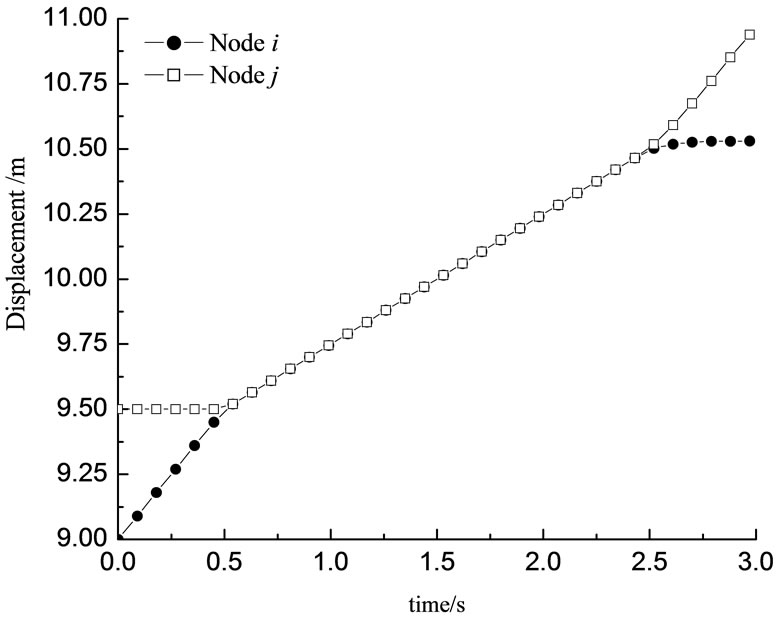
Figure 8. Displacement of contact node of central collision of beam.
the results of the collision force, displacement and velocity of contact node i and j are shown in Figures 9-11, respectively.
It is shown in Figures 9 and 10 that there are three times collision between beams A and B, i.e. the elastic wave propagated three times during the whole time domain. A large deformation has been made due to a small stiffness of beams.
3.3. Node-to-Surface Transverse Collision of Beam
Parameters of beams are the same as one in 2.2 but x coordinate of the contact points is 4.5 m. If beam B is divided into 10 elements, then it is a node-to-surface collision. If beam B is divided into 20 elements, then it is a node-to-node collision.
Linear interpolation method is chosen for the node-tosurface contact, the collision force is distri-buted to the nodes j and j + 1 by the static equivalent principle. Displacements, which is gotten from interpolation and non-interpolation of the point at x = 4.5 m, are shown in Figure 12.
It is shown in Figure 12 that the results obtained from different models are close. The maximal displacement in x = 4.5 m gotten by a interpolation model is smaller than that gotten by a subdivision model. When beam B is subdivided into 20 elements, the results are more exact. But the collision problem is very sensitive to the value of time step, so it may take much more time to calculate as using a subdivision model. As a result, it is suggested a suitable large size of elements should be chosen to save compute time within the error allowed.
3.4. Oblique Collision of Beam
As shown in Figure 5, the length of beam A is 5 m, and
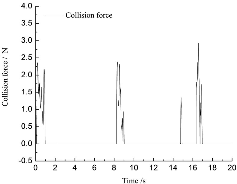
Figure 9. Force of transverse collision of beam.
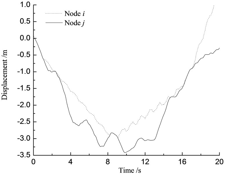
Figure 10. Vertical displacement of contact node.
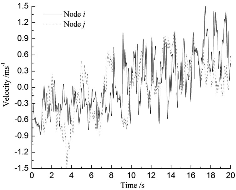
Figure 11. Vertical velocity of contact node.
is 10 m of beam B, and the area of section of beams is 0.4 m2. Beam A, with v0 = 1 m/s and rake angle α, moves to a simply supported beam B. Material constant: Young’s modulus is E = 1.8e11 N/m2, the density of beams is ρ = 8400 kg/m3. Friction coefficient is μ = 0.3. Time step takes Δt = 0.00001 s.
It is analyzed in section 1 that the beam A will rotate when the collision happens and the angle α will change with time. Thus it is easily known that the dynamic contact position will change with angle α too. Now it is shown in Figure 13, the displacements of node i in beam A and the central point j of beam B are obtained with three different initial angle α0 = 90˚, 60˚ and 45˚. And the collision force obtained with two different initial angle α0 = 90˚ and 45˚ is shown in Figure 14.
It is shown in Figure 13 that the vertical deformation of beam B is not the same when having different value of angle α. With the angle α decreased, the displacement of beam B in y direction becomes smaller, so do the rebound velocity in vertical direction and normal collision force. The primary reason may be that with α0 decreased, the velocity of beam A in vertical direction also becomes smaller. And in the result, the impact on beam B becomes smaller too.
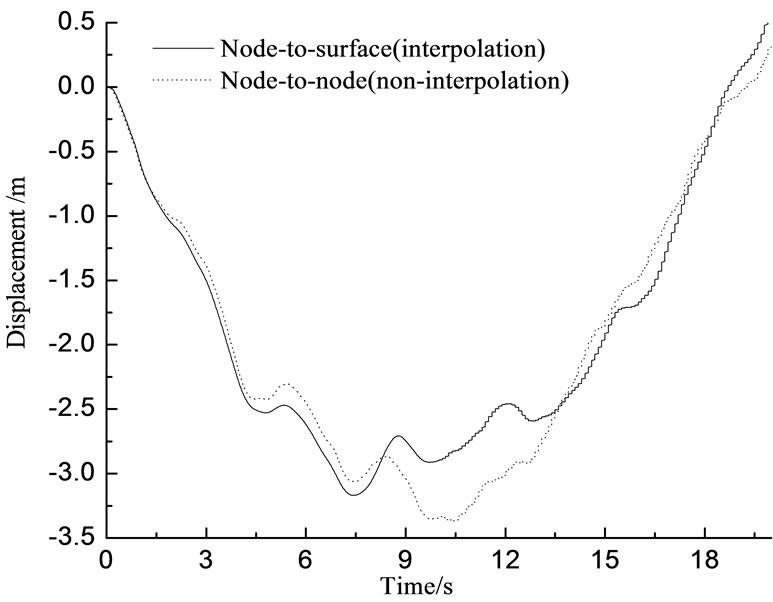
Figure 12. Vertical displacement of contact point obtained from interpo-lation and non-interpolation model.
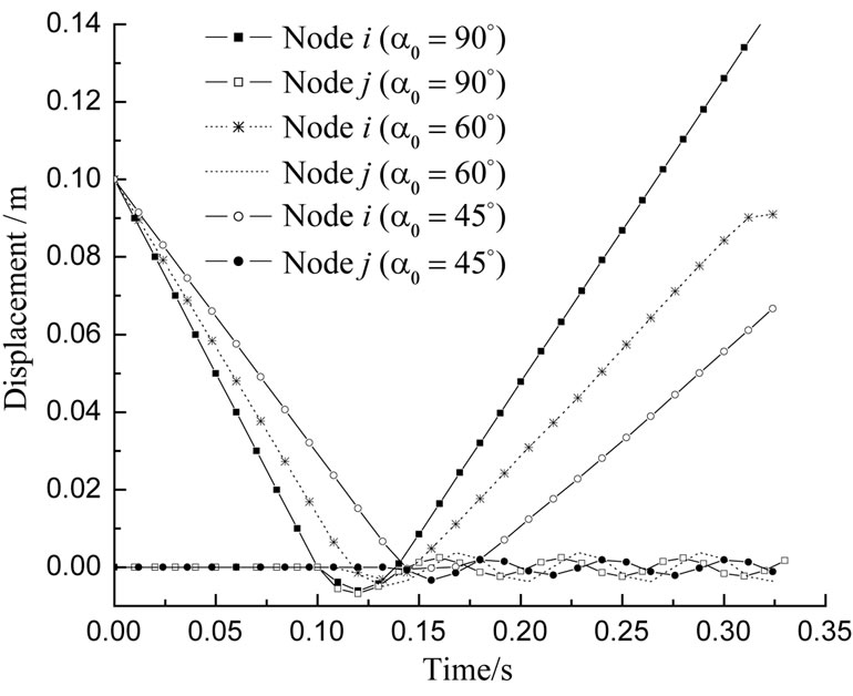
Figure 13. Displacements of beams with oblique collision in direction y.
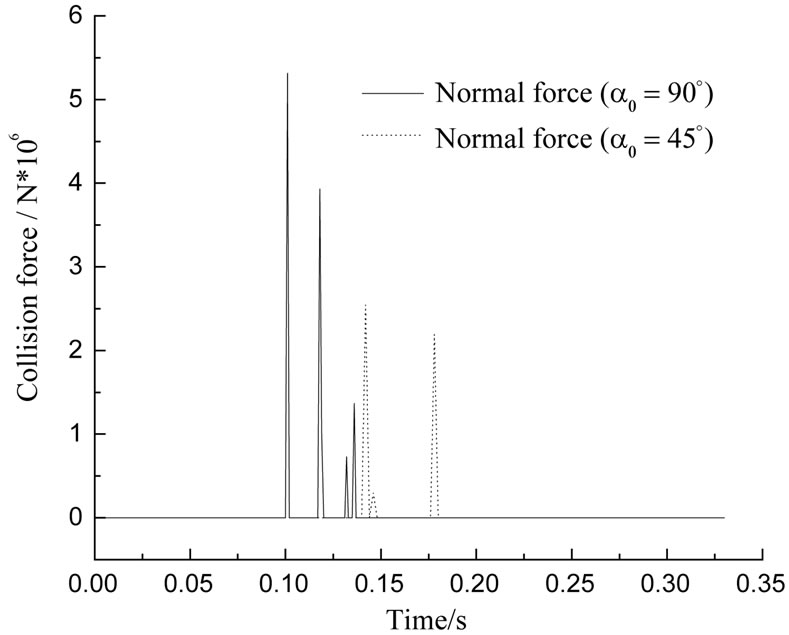
Figure 14. Normal collision force.
4. Conclusions
Collision problem are widespread in civil and mechanical engineering. Investigated the beam element and compared with the analytical solution, it is assured that the finite element dynamic calculation program developed in this article is reliable. Node-to-surface dynamic contact analysis method should be applied for the oblique collision owing to that the node-to-node model is just a special case during the process of a dynamic contact. The time step for integration should be very small to get a convergence result because the time for the wave propagation is small and the collision force is large in the transverse collision.
5. REFERENCES
- T. A. Lauren, “Computational Contact and Impact Mechanics: Fundamentals of Modeling Interfacial Phenomena in Nonlinear Finite Element Analysis,” Spring-Verlag Berlin, Herdelberg and New York, 2002.
- D. Baraff, “Issues in Computing Contact Forces for Non-Penatrating Rigid Bodies,” Algorithmica, Vol. 10, No. 2-4, 1993, pp. 292-352. doi:10.1007/BF01891843
- S. Liu, “Numerical Method and Test Study for Dynamic Contact Problems in Civil Engineering (Chinese),” Ph.D. Thesis, Tsinghua University, Beijing, 2000.
- H. H. Ruan and T. X. Yu, “Collision between MassSpring System,” International Journal of Impact engineering, Vol. 31, No. 3, 2005, pp. 267-288. doi:10.1016/j.ijimpeng.2003.11.003
- H. H. Ruan and T. X. Yu, “Local Deformation Models in Analyzing Beam-on-Beam Collision,” International Journal of Mechanical Sciences, Vol. 45, No. 3, 2003, pp. 397-423. doi:10.1016/S0020-7403(03)00082-1
- J. E. Escalona, J. Mayo and J. Dominguez, “A New Numerical Method for the Dynamic Analysis of Impact Loads in Flexible Beams,” Mechanism and Machine Theory, Vol. 34, No. 5, 1999, pp. 765-780. doi:10.1016/S0094-114X(98)00054-8
- S. Pashah, M. Massenzio and E. Jaxquelin, “Prediction of Structural Response for Low Velocity Impact,” International Journal of Impact Engineering, Vol. 35, No. 2, 2008, pp. 119-132. doi:10.1016/j.ijimpeng.2006.12.006
- Z. H. Liu and X. C. Yin, “Multiple Elastic-Plastic Impacts between Free-Free Beam and Simply-Supported Beam (Chinese),” Journal of Mechanic Engineering, Vol. 46, No. 10, 2010, pp. 47-53. doi:10.3901/JME.2010.10.047
- T. Narabayashi, K. Shibake, A. Ishizaka and K. Ozaki, “Effects of Key Parameters on Energy Distribution and Kinetic Characteristics in Collision of Bar and Beam,” Journal of Sound and Vibration, Vol. 308, No. 3-5, 2007, pp. 548-562. doi:10.1016/j.jsv.2007.05.008
- H. H. Ruan and T. X. Yu, “Experimental Study of Collision between a Free-Free Beam and Simple-Supported Beam,” International Journal of Impact Engineering, Vol. 32, No. 1-4, 2005, pp. 416-443. doi:10.1016/j.ijimpeng.2005.03.003

