Open Journal of Applied Sciences
Vol. 3 No. 1 (2013) , Article ID: 29520 , 4 pages DOI:10.4236/ojapps.2013.31016
An Integrated Collector Storage Solar Water Heater and Study of Its Temperature Stratification
School of Applied Sciences, Bharati Vidyapeeth’s College of Engineering, New Delhi, India
Email: atishmozumder@gmail.com
Received December 10, 2012; revised January 10, 2013; accepted 17, 2013
Keywords: Solar Water Heater; Integrated Collector Storage; Temperature Stratification
ABSTRACT
In this paper we describe an integrated collector storage solar water heater for the North Western region of India for use as domestic water heater during the winter season and present the experimental results of temperature stratification. The system consists of a steel water storage tank with azimuthal orientation such that its walls face south east, south west, north east and North West directions. The sunlit walls (south east and south west) and the top cover surface of the storage tank are covered with transparent insulation material (TIM) and the off-sunlit sides with opaque insulation. Experimental results show that the top layer is at the highest temperature. The top layer is drained using a new design of the outlet. The system can be used in rural areas or as a pre heater in more affluent households. The system can return the cost of conversion of the storage tank into a Solar Water Heater in one winter season by saving the cost of electrical energy required for heating water during winter months.
1. Introduction
Solar water heating has been identified as an important means to combat pollution due to fossil fuel burning [1-3]. In India water heating has large potential because of abundant sunshine available including the hilly region [4]. In the rural areas of India, the most common fuel is still the biomass. The winter months in the northern region of the country the water is chilly with temperature reaching below 1˚C in the peak winter. Warm water (few degrees above the body temperature) is needed for taking a bath. In the rural areas people are seen using the ground water that is somewhat more pleasant with temperature just above 20˚C. About 20 L of warm water is needed per person per day in the winter months.
Many designs have been investigated to obtain high efficiency of energy conversion [5,6]. The most commonly used solar water heater for domestic sector is natural circulation type wherein the hot water is circulated between collector and storage water tank. These are referred to as thermpsyphon systems and have been extensively investigated [7,8]. Such systems are available commercially and are partially subsidized by Government agencies. However despite all these incentives it has not been able to achieve mass scale popularity in the domestic sector in north western region of India. In the cities of Bangalore and Mysore such systems are popular because of the need of warm water in the major part of the year and a strong governmental incentive in the form of rebate in electrical energy rate. In the commercial sector like hotels, hospitals, student’s hostels thermosyphon systems have been installed by governmental directive. In the textile industry such devices are popular energy saving device.
It is not difficult to find the reason for slow growth in the thermosyphon solar water heating systems in the domestic sector in the North Western region of India. The north western region excluding the Himalayan regions have a prolonged summer when there is no requirement of any water heating. The winter is short (from November till February) and in the months of December and January when it is at its peak the occurrence of heavy fog reduces the availability of sunshine. Thus an expensive solar water system (2.6 to 3 USD/L) remains idle for major part of the year.
The motivation behind the present work is to design an integrated collector storage system a for semi urban and rural areas of North Western India which is cost effective, can be installed easily with locally available materials and components and easy to maintain. The integrated collector storage system has also been investigated by Kaushika and Bannerjee [9] who suggested and analyzed a configuration which consists of a storage tank cuboid in shape, transparently heated at the top surface and insulated at all other sides. Subsequently Goetzberger [10]
and Rommel et al. [11] considered a cubic water storage tank using transparent insulation on its top surface as well as side walls and reported a solar energy gain of about 40%. Kaushika and Sharma [12] experimentally investigated the solar gains of systems with above configurations. The system with the configuration involving the cuboid storage tank exhibits appreciable solar gain only if the heated plane is inclined to the horizontal at an angle in excess of 20˚. The water containment is a problem in such systems. Furthermore these authors used honeycomb based transparent insulating material which was rather cost intensive (USD 100/m2) so the concept did not receive mass scale adoption. Garnier et al. [13] studied the temperature stratification of integrated collector storage system in Scottish weather condition.
2. Description and Operation of the System
The system consists of a roof top steel water storage tank. In our set up the storage tank is nearly cubical in shape and is made of galvanized steel sheets of 16 gauge (88 cm × 88 cm × 78 cm). The azimuthal orientation of the storage tank is such that its walls face south east, south west, north east and north west directions which has been found to the best orientation for the solar energy gain for a cuboid [12]. The sunlit walls and top surface of the tank are blackened (using black Japan, a coal tar enamel paint) and covered with transparent insulating material. The off sunlit walls and the bottom surface are covered with sheets of polystyrene (thermocole) of 1 cm thickness, which is a good insulating material. The transparent insulating material used is locally available air bubbled polythene sheets. It is pasted on the blackened walls with bubbled surface inside. This forms an air film of small thickness which is non convective and acts as excellent transparent insulator. Both these materials are used in packaging and can be obtained easily. The transparent insulation material degrades in one season and was replaced at the beginning of the each winter season. It was dusted and cleaned time to time to remove the accumulated dust. The thermocole insulation does not degrade and can last for two to three years but curiously attacked by the pigeons. Figure 1 shows the front view of the tank with its transparent insulation cover.
Figure 1. Front view of the integrated collector storage solar water heater.
The tank which may contain the residual water from previous night is filled fully with fresh water from the mains in the morning so that its top layer touches the top surface of the tank. The inlet and the outlet valves are closed and the water is left undisturbed throughout the day when it absorbs the solar heat. Solar heat is conducted through the top surface and the walls facing south east and south west and the water in the tank is heated. The transparent insulation cover enables efficient absorption of solar radiant energy and minimization of thermal loss. In the evening the outlet valve is opened and the hot water from the tank is utilized. Depending upon the consumption some water remains in the tank which becomes cold during the night.
3. Result and Discussion
The measurements were carried out during the winter months of November, December, January and February on sunny days during the years 2008-2010. A total of 48 observations were taken spread equally over the four months listed above to obtain the heating pattern. The water temperature in the tank is measured using a thermocouple thermometer in the morning at 8 am and in the afternoon 5 pm. The input water mixes with the residual water due to the turbulence created by the incoming water. This results in temperature of the water the same throughout the tank. At 5 pm the layers of water shows temperature stratification. The top layer is found to be at the highest temperature gaining about 10˚C to 12˚C depending upon the weather conditions. The actual temperature of this layer may be 30˚C to 34˚C as the initial temperature of water in the tank varies between 20˚C to 22˚C. Temperature of the water decreases sharply as the depth increases. Beyond the depth of 20 cm the water temperature is constant and on an average 2˚C - 2.5˚C higher than the initial water temperature.
In Table 1 the average experimental values of the ratio of the temperatures top layer and the bottom layer  are shown. The values obtained are larger than the values for Scottish weather condition as reported by Garnier et al. [13]. Figure 2 shows the temperature variation for a typical sunny day in February.
The temperature stratification can be due to the following mechanism. In the morning the sun is low and the
Figure 2. The variation of water temperature with depth at 5 pm on a typical sunny day of February.
Table 1. Weather data of New Delhi (28.58˚N, 77.20˚E), and values of parameters obtained by the field experiment with the ISC SWH.
south east surface of the tank receives the sun with lowest angle. The temperature of the south east surface will be higher compared to the other sunlit surfaces. The heat is conducted through the sheet and heats up the water that is adjacent to its inner surface. The heated water whose density is the lowest will rise up to the top of the tank due to force of buoyancy. In the afternoon the south west surface will become hottest and in same way hottest water will reach the topmost layer of the tank. This way the topmost layer will accumulate the hottest water in the tank and since this water will be the lightest will remain there. The heat conducted by the top cover will heat up the top layer of water further.
During the morning hours while the maximum absorption is taking place on the surface facing the south east, surface facing south west and the top surface also gains heat but with a lower rate. This produces hot water at lower temperature. This water does not rise till the top but settles at lower depth. Similarly in the afternoon the south east wall will generate hot water at lower temperature that settles at lower depth. Thus in the morning a convection currents sets in at a depth more than 20 cm when the hot water from south western wall (above 2.5˚C from initial temperature) rises up and is being replaced by the colder inner vertical layers. Similar convection currents will occur for south eastern wall in the afternoon. These convection currents homogenize the temperature throughout the lower layers of the tank at depth larger than 20 cm.
We observe that the temperature of the top layer is at 30˚C to 32˚C (gain ~10˚C) during the peak winter months. The volume of water in the top layer is about 80 L sufficient for four persons. The temperature of water may be just pleasant for November, December and February. In January the water has to be further heated as it is the coldest month with low sunshine on many days due to fog in this region.
The thermal energy gain, Q is computed using
where mi is the mass of ith layer, s the specific heat of water  and ΔTi the increase in temperature of the ith layer. The average thermal energy gain for the four months namely November December, January and February is shown in Table 1. We find that approximately 3 kW·h of energy gain occurs per day. If the system is used for 100 days in one year the energy saved would be 300 kW·h. The additional cost of conversion of the storage tank into water heater can be recovered in first year.
We have conducted a few observations when the top water surface is below the ceiling level and doesn’t touch top of the tank. In such a situation the heat gain through top surface by conduction becomes small. The observations of temperature stratification reveal a very interesting fact. The top layer is found again to be at the highest temperature with temperature gain of 8˚C which is 2˚C lower if the water surface touches the ceiling. The gain of temperature falls sharply till the depth of 20 cm beyond which it is constant. The layers below 20 cm show a gain of 2˚C - 2.5˚C which is the same as in the previous case. This shows that the side walls of the tank play a more important role in temperature gain of the water in the tank
4. Draining the Hot Water
As we have seen the temperature of water is highest at the top of the tank. This top layer of water however would be normally available after the almost the whole water has been drained. In our system the hot water in
the top layer is drained using new design. A flexible pipe fastened to an empty plastic bottle that works as float is attached to the outlet pipe. The arrangement is shown in Figure 3. In our system outlet pipe supplies water in the kitchen and bathroom to conventional water heaters that run on electricity.
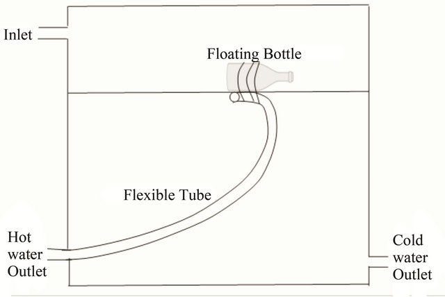
Figure 3. Arrangement to drain the top layer of water
The heated water at the highest temperature is available at 5 pm when it can be utilized. If the water is not utilized the temperature of the water next morning falls back to the initial temperature. This is the biggest drawback of the system. The water temperature may not also be sufficiently high as people prefer slightly higher temperatures. Therefore the system can be used as pre heater. However the saving in the cost of electrical energy will be substantial.
5. Conclusion
The simple integrated collector storage solar water heater studied can be used as a pre-heater for domestic and industrial applications. The study of temperature stratification reveals that the thermal energy gain is confined to the top 20 cm of the storage tank. The top layer temperature is at 30˚C during the peak winter months. A more expensive transparent honeycomb insulating material will increase the efficiency of the system but may only be used on the top cover surface and upper 20 cm of the sun lit walls of the storage tank.
REFERENCES
- S. Kalogirou, “Environmental Benefits of Domestic Solar Energy Systems,” Energy Conversion and Management, Vol. 45, No. 18-19, 2004, pp. 3075-3092.
- S. Mirasgedis, D. Diakoulaki and D. Assimacopoulos, “Solar Energy and the Abatement of Atmospheric Emissions,” Renewable Energy, Vol. 7, No. 4, 1996, pp. 329- 338. doi:10.1016/0960-1481(96)00014-6
- D. Haralambopoulos and I. Spilanis, “Identification and Assessment of Environmental Benefits from Solar Hot Water Production,” Renewable Energy, Vol. 11, No. 2, 1997, pp. 177-189. doi:10.1016/S0960-1481(96)00127-9
- P. Purohit and A. Michaelowa, “CDM Potential of Solar Water Heating Systems in India,” Solar Energy, Vol. 82, No. 9, 2008, pp.799-811. doi:10.1016/j.solener.2008.02.016
- A. Doraswami, “Government Incentives in India for Decentralized Energy Systems,” Energy for sustainable Development, Vol. 1, No. 1, 1994, pp. 51-57.
- S. Jaisankar, J. Anath, S. Thulasi, S. T. Jayasuthakar and K. N. Sheeba, “A Comprehensive Review on Solar Water Heaters,” Renewable and Sustainable Energy Reviews, Vol. 15, No. 6, 2011, pp. 3045-3050.
- S. Kalogirou, “Thermal Performance, Economic and Environmental Life Cycle Analysis of Thermosiphon Solar Water Heaters,” Solar Energy, Vol. 83, No. 1, 2009, pp. 39-48. doi:10.1016/j.solener.2008.06.005
- N. M. Nahar, “Year Round Performance and Potential of a Natural Circulation Type of Solar Water Heater in India,” Energy and Buildings, Vol. 35, No. 3, 2003, pp. 239-247. doi:10.1016/S0378-7788(02)00091-9
- N. D. Kaushika and M. Bannerjee, “Honeycomb Solar Ponds: Evaluation of Application,” Proceeding of Solar World Congress, Perth, 14-19 August 1983, pp. 246-247.
- A. Goetzberger, “Seasonal Storage of Thermal Energy with Radiatively Heated Storage Walls,” International Journal of Solar Energy, Vol. 2, No. 6, 1984, pp. 521-535. doi:10.1080/01425918408909947
- M. V. Rommel, V. Wittwer and A. Goetzberger, “Thermal Energy Collector and Storage with Radiatively Heated Walls,” In: W. H. Bloss and F. Pfisterer, Eds., Advances in Solar Energy Technology, ISES, Hamburg, Vol. 2, 1987, p. 1553.
- N. D. Kaushika and P. P. Sharma, “Transparent Honeycomb Insulated Solar Thermal Systems for Energy Conservation,” Heat Recovery Systems & CHP, Vol. 14, No. 1, 1994, pp. 37-44.
- C. Garnier, J. Currie and T. Muneer, “Integrated Collector Storage Solar Water Heater: Temperature Stratification,” Applied Energy, Vol. 86, No. 9, 2009, pp. 1465-1469. doi:10.1016/j.apenergy.2008.12.009
- A. Mani and S. Rangarajan, “Solar Radiation over India,” Allied Publishers, New Delhi, 1982.