Paper Menu >>
Journal Menu >>
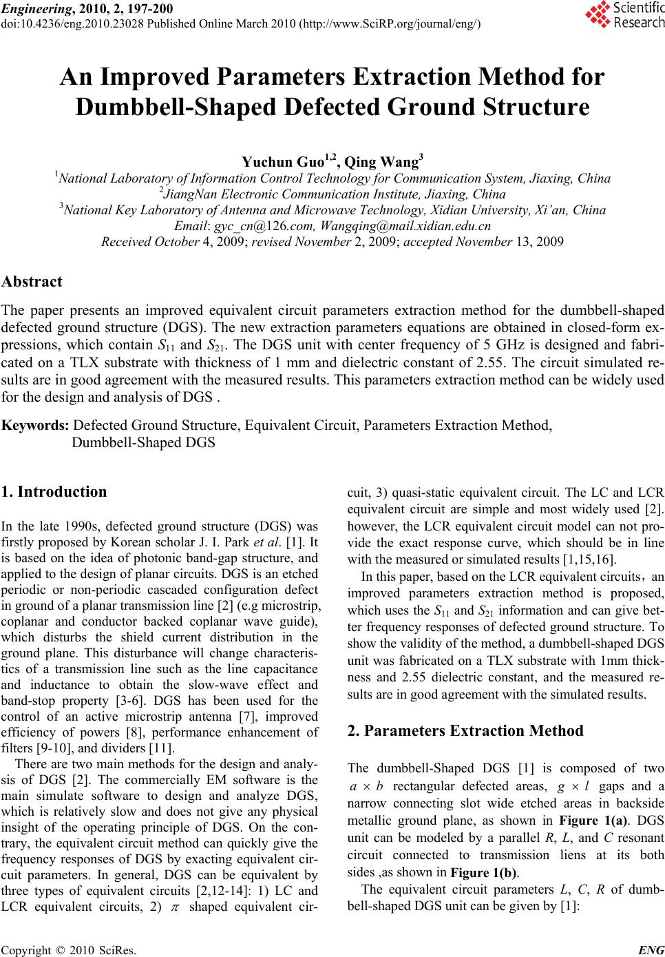 Engineering, 2010, 2, 197-200 doi:10.4236/eng.2010.23028 lished Online March 2010 (http://www.SciRP.org/journal/eng/) Copyright © 2010 SciRes. ENG Pub An Improved Parameters Extraction Method for Dumbbell-Shaped Defected Ground Structure Yuchun Guo1,2, Qing Wang3 1National Laboratory of Information Control Technology for Communication System, Jiaxing, China 2JiangNan Electronic Communication Institute, Jiaxing, China 3National Key Laboratory of Antenna and Microwave Technology, Xidian University, Xi’an, China Email: gyc_cn@126.com, Wangqing@mail.xidian.edu.cn Received October 4, 2009; revised November 2, 2009; accepted November 13, 2009 Abstract The paper presents an improved equivalent circuit parameters extraction method for the dumbbell-shaped defected ground structure (DGS). The new extraction parameters equations are obtained in closed-form ex- pressions, which contain S11 and S21. The DGS unit with center frequency of 5 GHz is designed and fabri- cated on a TLX substrate with thickness of 1 mm and dielectric constant of 2.55. The circuit simulated re- sults are in good agreement with the measured results. This parameters extraction method can be widely used for the design and analysis of DGS . Keywords: Defected Ground Structure, Equivalent Circuit, Parameters Extraction Method, Dumbbell-Shaped DGS 1. Introduction In the late 1990s, defected ground structure (DGS) was firstly proposed by Korean scholar J. I. Park et al. [1]. It is based on the idea of photonic band-gap structure, and applied to the design of planar circuits. DGS is an etched periodic or non-periodic cascaded configuration defect in ground of a planar transmission line [2] (e.g microstrip, coplanar and conductor backed coplanar wave guide), which disturbs the shield current distribution in the ground plane. This disturbance will change characteris- tics of a transmission line such as the line capacitance and inductance to obtain the slow-wave effect and band-stop property [3-6]. DGS has been used for the control of an active microstrip antenna [7], improved efficiency of powers [8], performance enhancement of filters [9-10], and dividers [11]. There are two main methods for the design and analy- sis of DGS [2]. The commercially EM software is the main simulate software to design and analyze DGS, which is relatively slow and does not give any physical insight of the operating principle of DGS. On the con- trary, the equivalent circuit method can quickly give the frequency responses of DGS by exacting equivalent cir- cuit parameters. In general, DGS can be equivalent by three types of equivalent circuits [2,12-14]: 1) LC and LCR equivalent circuits, 2) shaped equivalent cir- cuit, 3) quasi-static equivalent circuit. The LC and LCR equivalent circuit are simple and most widely used [2]. however, the LCR equivalent circuit model can not pro- vide the exact response curve, which should be in line with the measured or simulated results [1,15,16]. In this paper, based on the LCR equivalent circuits,an improved parameters extraction method is proposed, which uses the S11 and S21 information and can give bet- ter frequency responses of defected ground structure. To show the validity of the method, a dumbbell-shaped DGS unit was fabricated on a TLX substrate with 1mm thick- ness and 2.55 dielectric constant, and the measured re- sults are in good agreement with the simulated results. 2. Parameters Extraction Method The dumbbell-Shaped DGS [1] is composed of two ab rectangular defected areas, g l gaps and a narrow connecting slot wide etched areas in backside metallic ground plane, as shown in Figure 1(a). DGS unit can be modeled by a parallel R, L, and C resonant circuit connected to transmission liens at its both sides ,as shown in Figure 1(b). The equivalent circuit parameters L, C, R of dumb- bell-shaped DGS unit can be given by [1]: 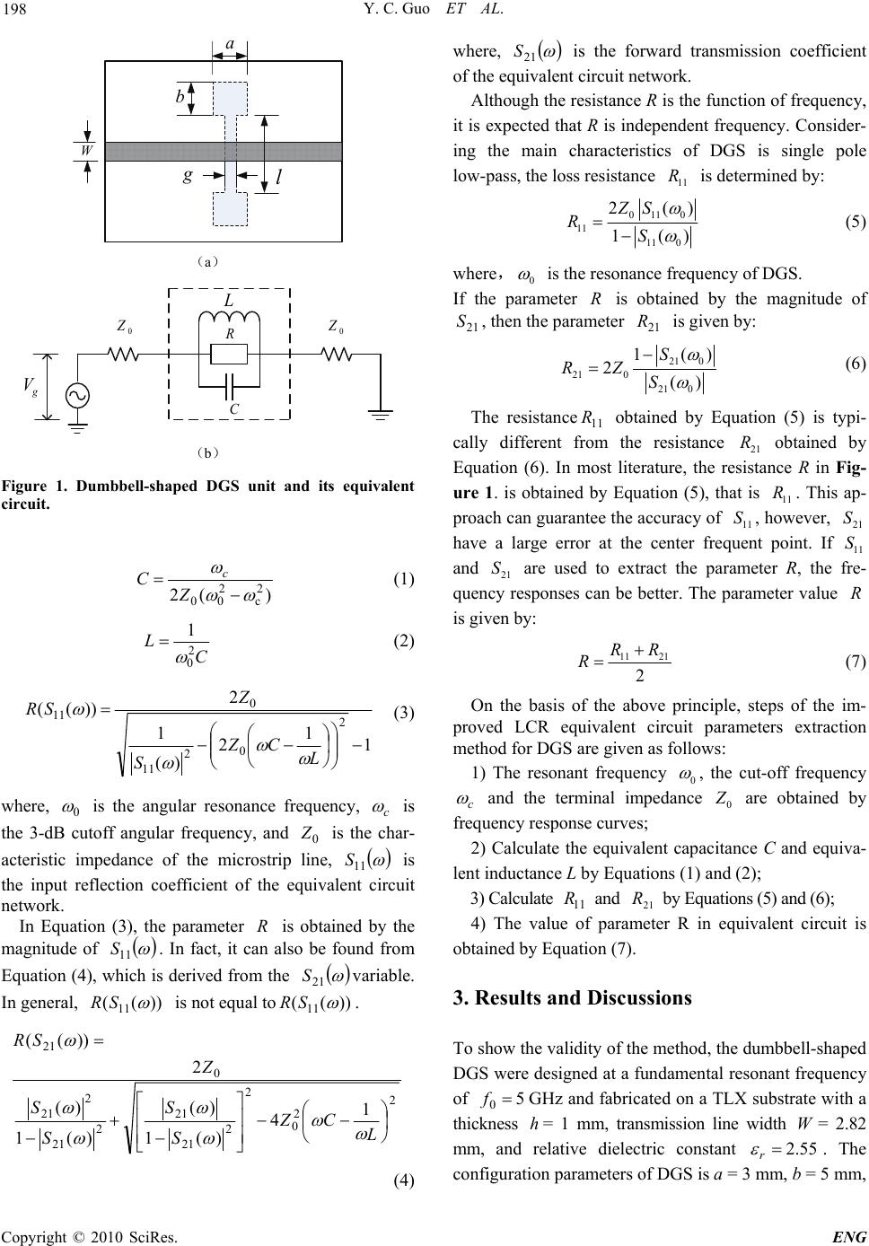 Y. C. Guo ET AL. 198 b a g l W (a) 0 Z g V 0 Z L R C (b) Figure 1. Dumbbell-shaped DGS unit and its equivalent circuit. )(2 2 c 2 00 Z Cc (1) C L2 0 1 (2) 1 1 2 )( 1 2 ))(( 2 0 2 11 0 11 L CZ S Z SR (3) where, 0 is the angular resonance frequency, c is the 3-dB cutoff angular frequency, and is the char- acteristic impedance of the microstrip line, 0 Z 11 S is the input reflection coefficient of the equivalent circuit network. In Equation (3), the parameter is obtained by the magnitude of R 11 S. In fact, it can also be found from Equation (4), which is derived from the 21 Svariable. In general, ))((11 SR is not equal to))((11 SR . 2 2 0 2 2 21 21 2 21 2 21 0 21 1 4 )(1 )( )(1 )( 2 ))(( L CZ S S S S Z SR (4) where, 21 S is the forward transmission coefficient of the equivalent circuit network. Although the resistance R is the function of frequency, it is expected that R is independent frequency. Consider- ing the main characteristics of DGS is single pole low-pass, the loss resistance is determined by: 11 R 011 0 11 11 0 2( 1() ZS RS ) (5) where,0 is the resonance frequency of DGS. If the parameter is obtained by the magnitude of , then the parameter is given by: R 21 S21 R 21 0 21 0 21 0 1( 2() ) S RZ S (6) The resistance obtained by Equation (5) is typi- cally different from the resistance obtained by Equation (6). In most literature, the resistance R in Fig- ure 1. is obtained by Equation (5), that is . This ap- proach can guarantee the accuracy of , however, have a large error at the center frequent point. If and are used to extract the parameter R, the fre- quency responses can be better. The parameter value is given by: 11 R 21 R 11 S 11 R 21 S 11 S R 21 S 11 21 2 RR R (7) On the basis of the above principle, steps of the im- proved LCR equivalent circuit parameters extraction method for DGS are given as follows: 1) The resonant frequency 0 , the cut-off frequency c and the terminal impedance 0 Z are obtained by frequency response curves; 2) Calculate the equivalent capacitance C and equiva- lent inductance L by Equations (1) and (2); 3) Calculate and by Equations (5) and (6); 11 R21 R 4) The value of parameter R in equivalent circuit is obtained by Equation (7). 3. Results and Discussions To show the validity of the method, the dumbbell-shaped DGS were designed at a fundamental resonant frequency of 5 0 fGHz and fabricated on a TLX substrate with a thickness = 1 mm, transmission line width W= 2.82 mm, and relative dielectric constant h 55.2 r . The configuration parameters of DGS is a = 3 mm, b = 5 mm, Copyright © 2010 SciRes. ENG  Y. C. Guo ET AL. 199 g = 1 mm, l = 11 mm, respectively, as shown in Figure 2. From the measured data, we have the scattering parame- ter values, )( 011 S= –1.147 dB, )( 021 S= –25.624 dB. According to the equivalent circuit parameter extraction steps in section II, the LCR equivalent circuit parameters are L = 3.969uH, C = 0.2553pF, R = 1259.67 (= 608.647 , =1810.69), respectively. 11 R 21 R The measured results and equivalent circuit simulation results using the equivalent circuit parameters are shown in Figure 3. It can be seen that the equivalent circuit Figure 2. Fabricated DGS unit at resonance frequency 5GHz. 012345678910 -30 -25 -20 -15 -10 -5 0 R=1259.67 R21=1810.69 R11=608.647 S11-Measured S11(dB) Frequency(GHz) (a) 012345678910 -35 -30 -25 -20 -15 -10 -5 0 R=1259.67 R21=1810.69 R11=608.647 S21-Measured S21(dB) Frequency(GHz) (b) Figure 3. Measured and equivalent circuit simulated S-pa- rameters for various R. (a) S11 parameter; (b) S21 parameter. Table 1. Ealaulation equivalent circuit frequency responses and error for various resistance at center frequency. S11/dB S21/dB Resis- tance Circuit model MeasuredError Circuit model Measured Error R –0.664 0.483 –22.668 2.394 R11 –1.146 0.001 –18.155 6.907 R21 –0.467 –1.147 0.680 –25.273 –25.062 –0.211 simulation results show excellent agreement with meas- ured results; they have the same resonance frequency. Table 1 gives the S-parameters results of that compari- son at the center frequency. When the resistance takes , the accuracy of can be ensured, but have nearly 7dB error and if the resistance takes, the accuracy of can be ensured, but have 0.68 dB error. Calculated the S-parameters by the proposed method, the errors of S-parameter can be smaller. 11 R11 S 21 S21 R 21 S11 S Measured results show that the improved LCR equivalent circuit parameter extraction method is effec- tive, it can be used for DGS quick simulation and ensures higher accuracy. 4. Conclusions The equivalent circuit has been widely applied to simu- late the frequency responses of DGS by exacting equiva- lent circuit parameters. In this paper, an improved equi- valent circuit parameters extraction method for dumb- bell-shaped DGS is proposed. Compared with the con- venient methods,the proposed method can give the more accurate frequency response curves, it can be widely used in the design and analysis of DGS. 5. Acknowledgment The author is grateful to the reviewers for their profes- sional comments and valuable suggestion in this paper. 6. References [1] J. I. Park, C. S. Kim, J. Kim, et al., “Modeling of a photonic bandgap and its application for the low-pass filter design,” Asia Pacific Microwave Conference, Vol. 2, pp. 331-334, 1999. [2] L. H. Weng, Y. C. Guo, X. W. Shi, et al., “An overview on defencted ground structure,” Progress in Electromag- netics Research B, Vol. 7, pp. 173-189, 2008. [3] H. J. Chen, T. H. Huang, C. S. Chang, et al., “A novel cross-shape DGS applied to design ultra-wide stop-band low-pass filters,” IEEE Microwave and Wireless Compo- C opyright © 2010 SciRes. ENG 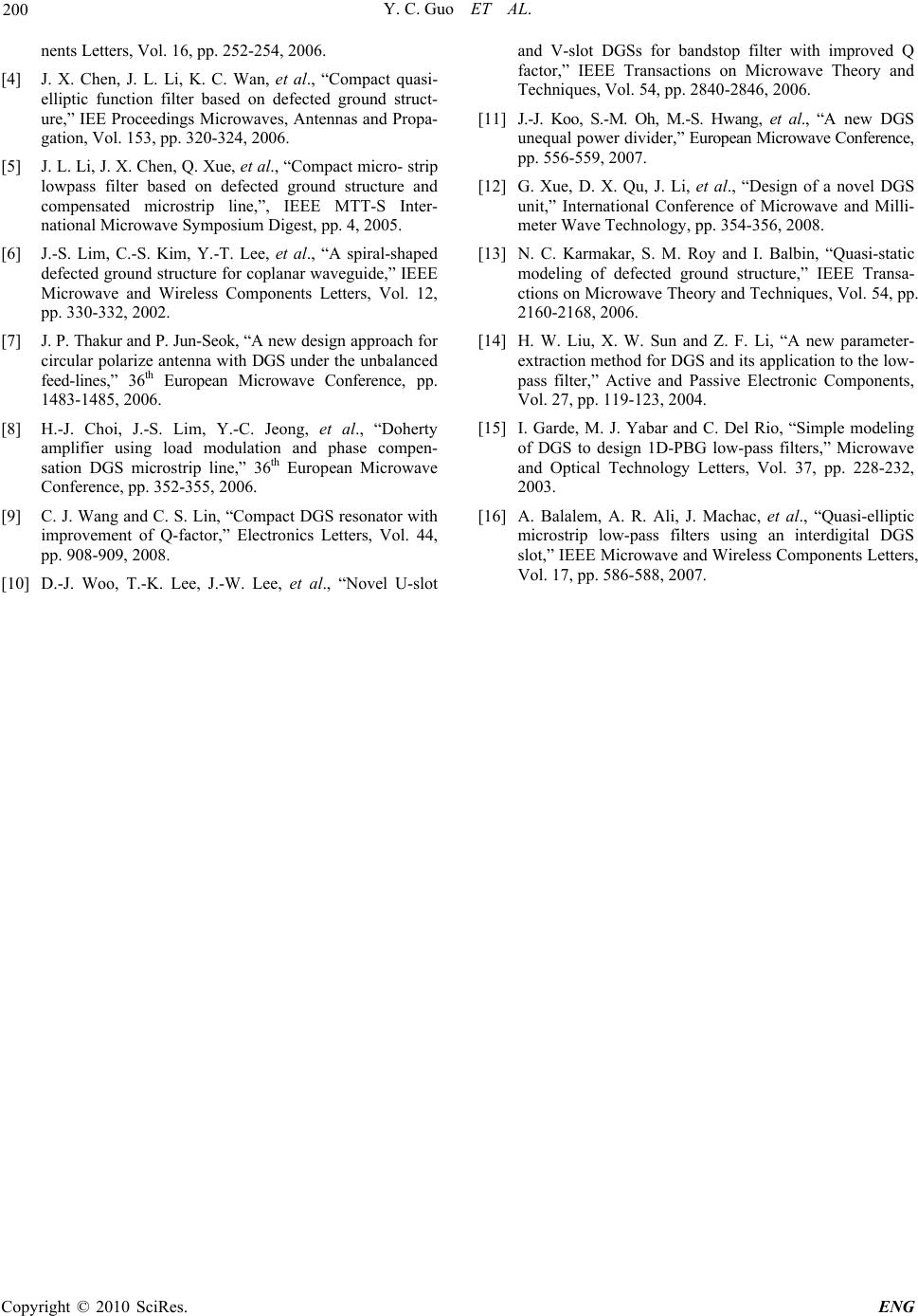 Y. C. Guo ET AL. Copyright © 2010 SciRes. ENG 200 nents Letters, Vol. 16, pp. 252-254, 2006. [4] J. X. Chen, J. L. Li, K. C. Wan, et al., “Compact quasi- elliptic function filter based on defected ground struct- ure,” IEE Proceedings Microwaves, Antennas and Propa- gation, Vol. 153, pp. 320-324, 2006. [5] J. L. Li, J. X. Chen, Q. Xue, et al., “Compact micro- strip lowpass filter based on defected ground structure and compensated microstrip line,”, IEEE MTT-S Inter- national Microwave Symposium Digest, pp. 4, 2005. [6] J.-S. Lim, C.-S. Kim, Y.-T. Lee, et al., “A spiral-shaped defected ground structure for coplanar waveguide,” IEEE Microwave and Wireless Components Letters, Vol. 12, pp. 330-332, 2002. [7] J. P. Thakur and P. Jun-Seok, “A new design approach for circular polarize antenna with DGS under the unbalanced feed-lines,” 36th European Microwave Conference, pp. 1483-1485, 2006. [8] H.-J. Choi, J.-S. Lim, Y.-C. Jeong, et al., “Doherty amplifier using load modulation and phase compen- sation DGS microstrip line,” 36th European Microwave Conference, pp. 352-355, 2006. [9] C. J. Wang and C. S. Lin, “Compact DGS resonator with improvement of Q-factor,” Electronics Letters, Vol. 44, pp. 908-909, 2008. [10] D.-J. Woo, T.-K. Lee, J.-W. Lee, et al., “Novel U-slot and V-slot DGSs for bandstop filter with improved Q factor,” IEEE Transactions on Microwave Theory and Techniques, Vol. 54, pp. 2840-2846, 2006. [11] J.-J. Koo, S.-M. Oh, M.-S. Hwang, et al., “A new DGS unequal power divider,” European Microwave Conference, pp. 556-559, 2007. [12] G. Xue, D. X. Qu, J. Li, et al., “Design of a novel DGS unit,” International Conference of Microwave and Milli- meter Wave Technology, pp. 354-356, 2008. [13] N. C. Karmakar, S. M. Roy and I. Balbin, “Quasi-static modeling of defected ground structure,” IEEE Transa- ctions on Microwave Theory and Techniques, Vol. 54, pp. 2160-2168, 2006. [14] H. W. Liu, X. W. Sun and Z. F. Li, “A new parameter- extraction method for DGS and its application to the low- pass filter,” Active and Passive Electronic Components, Vol. 27, pp. 119-123, 2004. [15] I. Garde, M. J. Yabar and C. Del Rio, “Simple modeling of DGS to design 1D-PBG low-pass filters,” Microwave and Optical Technology Letters, Vol. 37, pp. 228-232, 2003. [16] A. Balalem, A. R. Ali, J. Machac, et al., “Quasi-elliptic microstrip low-pass filters using an interdigital DGS slot,” IEEE Microwave and Wireless Components Letters, Vol. 17, pp. 586-588, 2007. |