Paper Menu >>
Journal Menu >>
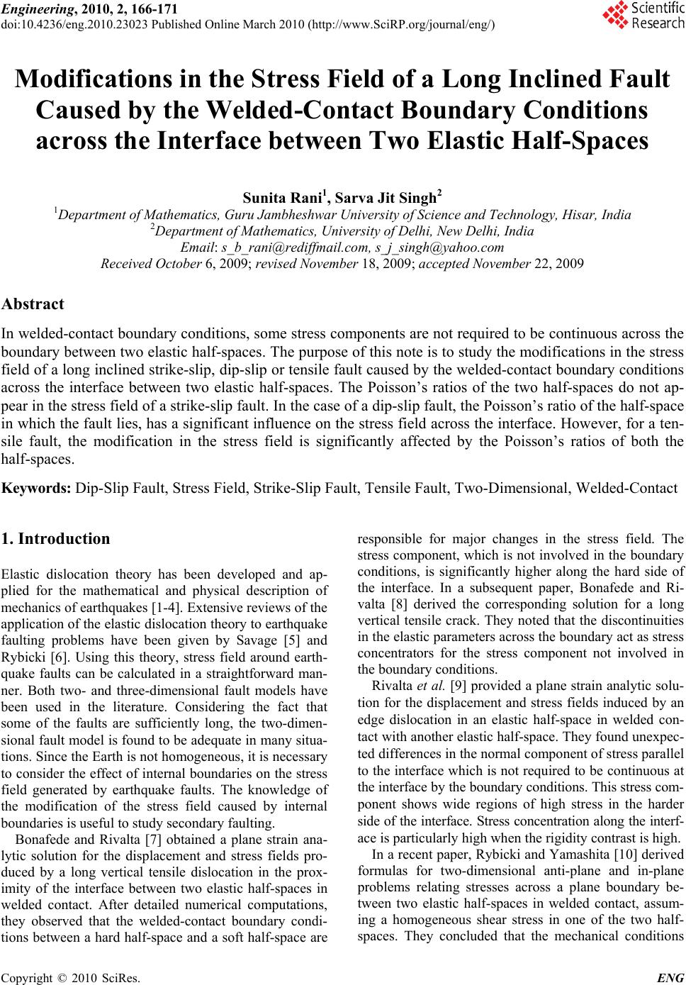 Engineering, 2010, 2, 166-171 doi:10.4236/eng.2010.23023 lished Online March 2010 (http://www.SciRP.org/journal/eng/) Copyright © 2010 SciRes. ENG Pub Modifications in the Stress Field of a Long Inclined Fault Caused by the Welded-Contact Boundary Conditions across the Interface between Two Elastic Half-Spaces Sunita Rani1, Sarva Jit Singh2 1Department of Mathematics, Guru Jambheshwar University of Science and Technology, Hisar, India 2Department of Mathematics, University of Delhi, New Delhi, India Email: s_b_rani@rediffmail.com, s_j_singh@yahoo.com Received October 6, 2009; revised November 18, 2009; accepted November 22, 2009 Abstract In welded-contact boundary conditions, some stress components are not required to be continuous across the boundary between two elastic half-spaces. The purpose of this note is to study the modifications in the stress field of a long inclined strike-slip, dip-slip or tensile fault caused by the welded-contact boundary conditions across the interface between two elastic half-spaces. The Poisson’s ratios of the two half-spaces do not ap- pear in the stress field of a strike-slip fault. In the case of a dip-slip fault, the Poisson’s ratio of the half-space in which the fault lies, has a significant influence on the stress field across the interface. However, for a ten- sile fault, the modification in the stress field is significantly affected by the Poisson’s ratios of both the half-spaces. Keywords: Dip-Slip Fault, Stress Field, Strike-Slip Fault, Tensile Fault, Two-Dimensional, Welded-Contact 1. Introduction Elastic dislocation theory has been developed and ap- plied for the mathematical and physical description of mechanics of earthquakes [1-4]. Extensive reviews of the application of the elastic dislocation theory to earthquake faulting problems have been given by Savage [5] and Rybicki [6]. Using this theory, stress field around earth- quake faults can be calculated in a straightforward man- ner. Both two- and three-dimensional fault models have been used in the literature. Considering the fact that some of the faults are sufficiently long, the two-dimen- sional fault model is found to be adequate in many situa- tions. Since the Earth is not homogeneous, it is necessary to consider the effect of internal boundaries on the stress field generated by earthquake faults. The knowledge of the modification of the stress field caused by internal boundaries is useful to study secondary faulting. Bonafede and Rivalta [7] obtained a plane strain ana- lytic solution for the displacement and stress fields pro- duced by a long vertical tensile dislocation in the prox- imity of the interface between two elastic half-spaces in welded contact. After detailed numerical computations, they observed that the welded-contact boundary condi- tions between a hard half-space and a soft half-space are responsible for major changes in the stress field. The stress component, which is not involved in the boundary conditions, is significantly higher along the hard side of the interface. In a subsequent paper, Bonafede and Ri- valta [8] derived the corresponding solution for a long vertical tensile crack. They noted that the discontinuities in the elastic parameters across the boundary act as stress concentrators for the stress component not involved in the boundary conditions. Rivalta et al. [9] provided a plane strain analytic solu- tion for the displacement and stress fields induced by an edge dislocation in an elastic half-space in welded con- tact with another elastic half-space. They found unexpec- ted differences in the normal component of stress parallel to the interface which is not required to be continuous at the interface by the boundary conditions. This stress com- ponent shows wide regions of high stress in the harder side of the interface. Stress concentration along the interf- ace is particularly high when the rigidity contrast is high. In a recent paper, Rybicki and Yamashita [10] derived formulas for two-dimensional anti-plane and in-plane problems relating stresses across a plane boundary be- tween two elastic half-spaces in welded contact, assum- ing a homogeneous shear stress in one of the two half- spaces. They concluded that the mechanical conditions 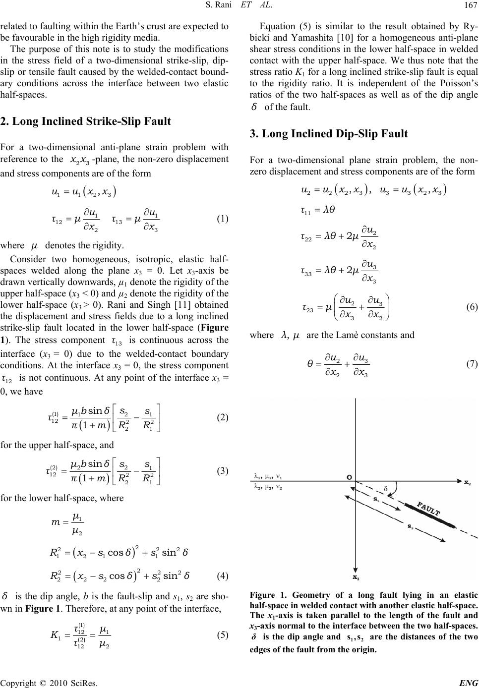 S. Rani ET AL. 167 related to faulting within the Earth’s crust are expected to be favourable in the high rigidity media. The purpose of this note is to study the modifications in the stress field of a two-dimensional strike-slip, dip- slip or tensile fault caused by the welded-contact bound- ary conditions across the interface between two elastic half-spaces. 2. Long Inclined Strike-Slip Fault For a two-dimensional anti-plane strain problem with reference to the -plane, the non-zero displacement and stress components are of the form 23 xx 1123 ,uuxx 1 12 13 23 u τμ τμ xx 1 u (1) where denotes the rigidity. μ Consider two homogeneous, isotropic, elastic half- spaces welded along the plane x3 = 0. Let x3-axis be drawn vertically downwards, µ1 denote the rigidity of the upper half-space (x3 < 0) and µ2 denote the rigidity of the lower half-space (x3 > 0). Rani and Singh [11] obtained the displacement and stress fields due to a long inclined strike-slip fault located in the lower half-space (Figure 1). The stress component is continuous across the interface (x3 = 0) due to the welded-contact boundary conditions. At the interface x3 = 0, the stress component is not continuous. At any point of the interface x3 = 0, we have 13 τ 12 τ (1) 2 1 12 22 21 sin 1 s μbδs τπmR R 1 (2) for the upper half-space, and (2) 22 1 12 22 21 sin 1 μbδss τπmR R (3) for the lower half-space, where 1 2 μ m μ 2 22 121 1 cos sinRxs δsδ 2 2 2 22 2222 cos sinRxs δsδ (4) δ is the dip angle, b is the fault-slip and s1, s2 are sho- wn in Figure 1. Therefore, at any point of the interface, (1) 12 1 1(2) 212 τμ K μτ (5) Equation (5) is similar to the result obtained by Ry- bicki and Yamashita [10] for a homogeneous anti-plane shear stress conditions in the lower half-space in welded contact with the upper half-space. We thus note that the stress ratio K1 for a long inclined strike-slip fault is equal to the rigidity ratio. It is independent of the Poisson’s ratios of the two half-spaces as well as of the dip angle of the fault. δ 3. Long Inclined Dip-Slip Fault For a two-dimensional plane strain problem, the non- zero displacement and stress components are of the form 2223 3323 ,, ,uu xxuu xx 11 τλθ 2 22 2 2u τλθμ x 3 33 3 2u τλθμ x 23 23 32 uu τμ xx (6) where are the Lamè constants and ,λμ 23 23 uu θxx (7) Figure 1. Geometry of a long fault lying in an elastic half-space in welded contact with another elastic half-space. The x1-axis is taken parallel to the length of the fault and x3-axis normal to the interface between the two half-spaces. is the dip angle and are the distances of the two edges of the fault from the origin. δ12 s,s C opyright © 2010 SciRes. ENG  S. Rani ET AL. 168 Rani and Singh [12] derived closed-form analytic ex- pressions for the displacements and stresses caused by a long inclined dip-slip fault located in an elastic half- space in welded contact with another elastic half-space. The stress components and are continuous across the interface as required by the welded-contact boundary conditions. In Figure 1, the origin is taken at the fault trace, that is at the point where the fault, if ex- tended, meets the interface x3 = 0. At the origin, the stress component is given by 23 τ33 τ 22 τ (1) 22 22 2 21 11 1sin2 αμb τCδ πss (8) for the upper half-space, and (2) 22 22 2 21 11 13 sin2 αμb τCδ πss (9) for the lower half-space, where 2 2 1 21 αv 2 2 1 12/ m C mmα (10) v2 being the Poisson’s ratio of the lower half-space. Therefore, at the origin, (1) 2 22 2 2(2) 2222 1 11 1 13 11 mv τCm K Cmv m τ2 v (11) We observe that the stress ratio K2 for a long inclined dip-slip fault depends upon the rigidity contrast m = µ1/µ2 and the Poisson’s ratio v2 of the lower half-space. It is independent of the Poisson’s ratio v1 of the upper half-space as well as of the dip angle . From (11), if , then . This implies that the stress near the interface generated in the upper half-space is less than the stress near the interface in the lower half-space in which the fault lies. On the other hand, if , then , implying that the stress generated near the interface in the upper half-space is more than the stress near the interface in the lower half-space. For δ 1m K 21K 2 1 1/mv 21 1 2 mv, the stress ( 2 ) 22 τ at the origin vanishes. It is interesting to compare (11) with the correspond- ing result of Rybicki and Yamashita [10] which, in our notation, is reproduced below: (1) 22 21 (2) 22 1 R τ Kmvm τ where v1 is the Poisson’s ratio of the upper half-space. The stress ratio K2R derived by Rybicki and Yamashita [10] depends upon the rigidity contrast m and the Pois- son’s ratio of the upper half-space. It is independent of the Poisson’s ratio of the lower half-space. It may be noted that while Rybicki and Yamashita [10] considered a homogeneous shear stress acting on an inclined plane in the lower medium, we have considered the stress field of a long inclined dip-slip fault in the lower half-space. Figure 2 shows the variation of K2 with m for v2 = 0.1, 0.2, 0.3, 0.4. Since K2 is independent of v1, for m = 1, we have K2 = 1 corresponding to the case when the two half-spaces have identical elastic parameters. In the range 0 < m < 1 (Figure 2(a)), we note that K2 < 1 and, for a given m, K2 decreases as v2 increases. The com- pressibility is given by 31-2 21+ v v μ . Therefore, in the range 0 < m < 1, for a given m, K2 increases as the com- pressibility of the lower half-space increases. In contrast, in the range 1 < m < 2 (Figure 2(b)), K2 > 1 and, for a 0 0.2 0.4 0.6 0.8 1.0 00.1 0.2 0.3 0.4 0.5 0.6 0.7 0.8 0.9 1.0 2 =0.1 2 =0.2 2 =0.3 2 =0.4 DIP-SLIP FAULT m K 2 (a) 1.0 1.5 2.0 2.5 3.0 3.5 4.0 4.5 5.0 5.5 6.0 1.0 1.11.2 1.3 1.41.5 1.61.7 1.81.9 2.0 2 =0.1 2 =0.2 2 =0.3 2 =0.4 DIP-SLIP FAULT m K 2 (b) Figure 2. Variation of the stress ratio K2 for a long dip-slip fault with the rigidity ratio 12 m=μ μ for four values of the Poisson’s ratio of the lower half-space for (a) 2 ν 0m1; (b) 12m. Copyright © 2010 SciRes. ENG 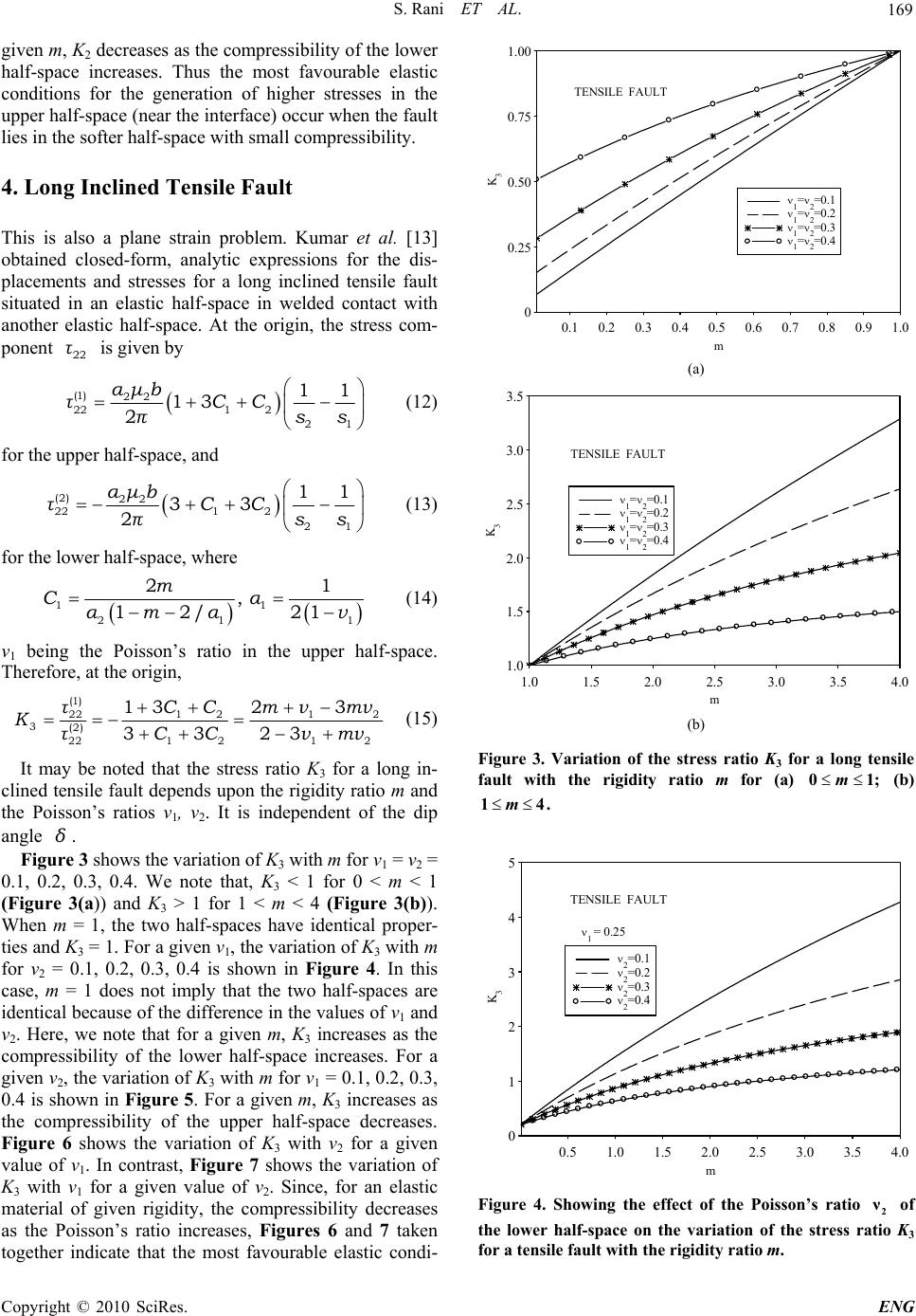 S. Rani ET AL. 169 given m, K2 decreases as the compressibility of the lower half-space increases. Thus the most favourable elastic conditions for the generation of higher stresses in the upper half-space (near the interface) occur when the fault lies in the softer half-space with small compressibility. 4. Long Inclined Tensile Fault This is also a plane strain problem. Kumar et al. [13] obtained closed-form, analytic expressions for the dis- placements and stresses for a long inclined tensile fault situated in an elastic half-space in welded contact with another elastic half-space. At the origin, the stress com- ponent is given by 22 τ (1) 22 221 2 21 11 13 2 αμb τCC πss (12) for the upper half-space, and (2) 22 221 2 21 11 33 2 αμb τCC πss (13) for the lower half-space, where 11 21 21 , 12/ 21 m Cα αmαv1 (14) v1 being the Poisson’s ratio in the upper half-space. Therefore, at the origin, (1 ) 221 212 3(2) 121 222 132 3 3323 τCC mνmν K CC νmντ (15) It may be noted that the stress ratio K3 for a long in- clined tensile fault depends upon the rigidity ratio m and the Poisson’s ratios v1, v2. It is independent of the dip angle . δ Figure 3 shows the variation of K3 with m for v1 = v2 = 0.1, 0.2, 0.3, 0.4. We note that, K3 < 1 for 0 < m < 1 (Figure 3(a)) and K3 > 1 for 1 < m < 4 (Figure 3(b)). When m = 1, the two half-spaces have identical proper- ties and K3 = 1. For a given v1, the variation of K3 with m for v2 = 0.1, 0.2, 0.3, 0.4 is shown in Figure 4. In this case, m = 1 does not imply that the two half-spaces are identical because of the difference in the values of v1 and v2. Here, we note that for a given m, K3 increases as the compressibility of the lower half-space increases. For a given v2, the variation of K3 with m for v1 = 0.1, 0.2, 0.3, 0.4 is shown in Figure 5. For a given m, K3 increases as the compressibility of the upper half-space decreases. Figure 6 shows the variation of K3 with v2 for a given value of v1. In contrast, Figure 7 shows the variation of K3 with v1 for a given value of v2. Since, for an elastic material of given rigidity, the compressibility decreases as the Poisson’s ratio increases, Figures 6 and 7 taken together indicate that the most favourable elastic condi- 0 0.25 0.50 0.75 1.00 0.1 0.2 0.3 0.4 0.5 0.6 0.7 0.8 0.9 1.0 1 = 2 =0.1 1 = 2 =0.2 1 = 2 =0.3 1 = 2 =0.4 TENSILE FAULT m K 3 (a) 1.0 1.5 2.0 2.5 3.0 3.5 1.0 1.5 2.0 2.5 3.0 3.54.0 1 = 2 =0.1 1 = 2 =0.2 1 = 2 =0.3 1 = 2 =0.4 TENSILE FAULT m K 3 (b) Figure 3. Variation of the stress ratio K3 for a long tensile fault with the rigidity ratio m for (a) (b) 0m1; 14m. 0 1 2 3 4 5 0.5 1.0 1.5 2.0 2.5 3.0 3.5 4.0 2 =0.1 2 =0.2 2 =0.3 2 =0.4 1 = 0.25 TENSILE FAULT m K 3 Figure 4. Showing the effect of the Poisson’s ratio 2 ν of the lower half-space on the variation of the stress ratio K3 for a tensile fault with the rigidity ratio m. C opyright © 2010 SciRes. ENG 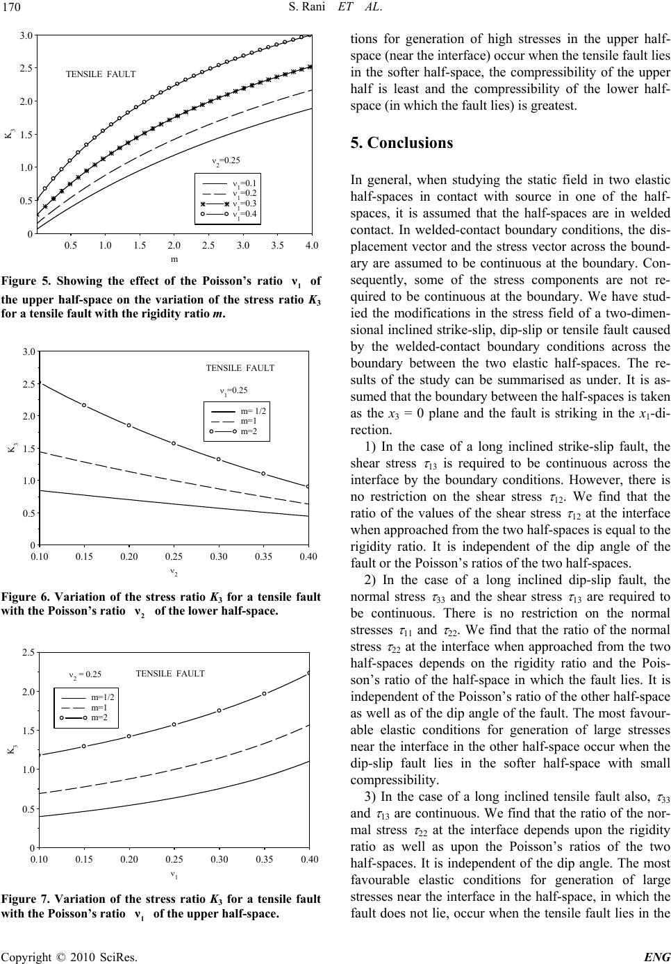 S. Rani ET AL. 170 0 0.5 1.0 1.5 2.0 2.5 3.0 0.5 1.0 1.5 2.02.5 3.03.5 4.0 1 =0.1 1 =0.2 1 =0.3 1 =0.4 TENSILE FAULT 2 =0.25 m K 3 Figure 5. Showing the effect of the Poisson’s ratio 1 ν of the upper half-space on the variation of the stress ratio K3 for a tensile fault with the rigidity ratio m. 0 0.5 1.0 1.5 2.0 2.5 3.0 0.10 0.150.20 0.250.300.35 0.4 0 m= 1/2 m=1 m=2 TENSILE FAULT 1 =0.25 2 K 3 Figure 6. Variation of the stress ratio K3 for a tensile fault with the Poisson’s ratio 2 ν of the lower half-space. 0 0.5 1.0 1.5 2.0 2.5 0.10 0.150.20 0.25 0.30 0.350.4 0 m=1/2 m=1 m=2 2 = 0.25TENSILE FAULT 1 K 3 Figure 7. Variation of the stress ratio K3 for a tensile fault with the Poisson’s ratio 1 ν of the upper half-space. tions for generation of high stresses in the upper half- space (near the interface) occur when the tensile fault lies in the softer half-space, the compressibility of the upper half is least and the compressibility of the lower half- space (in which the fault lies) is greatest. 5. Conclusions In general, when studying the static field in two elastic half-spaces in contact with source in one of the half- spaces, it is assumed that the half-spaces are in welded contact. In welded-contact boundary conditions, the dis- placement vector and the stress vector across the bound- ary are assumed to be continuous at the boundary. Con- sequently, some of the stress components are not re- quired to be continuous at the boundary. We have stud- ied the modifications in the stress field of a two-dimen- sional inclined strike-slip, dip-slip or tensile fault caused by the welded-contact boundary conditions across the boundary between the two elastic half-spaces. The re- sults of the study can be summarised as under. It is as- sumed that the boundary between the half-spaces is taken as the x3 = 0 plane and the fault is striking in the x1-di- rection. 1) In the case of a long inclined strike-slip fault, the shear stress 13 is required to be continuous across the interface by the boundary conditions. However, there is no restriction on the shear stress 12. We find that the ratio of the values of the shear stress 12 at the interface when approached from the two half-spaces is equal to the rigidity ratio. It is independent of the dip angle of the fault or the Poisson’s ratios of the two half-spaces. 2) In the case of a long inclined dip-slip fault, the normal stress 33 and the shear stress 13 are required to be continuous. There is no restriction on the normal stresses 11 and 22. We find that the ratio of the normal stress 22 at the interface when approached from the two half-spaces depends on the rigidity ratio and the Pois- son’s ratio of the half-space in which the fault lies. It is independent of the Poisson’s ratio of the other half-space as well as of the dip angle of the fault. The most favour- able elastic conditions for generation of large stresses near the interface in the other half-space occur when the dip-slip fault lies in the softer half-space with small compressibility. 3) In the case of a long inclined tensile fault also, 33 and 13 are continuous. We find that the ratio of the nor- mal stress 22 at the interface depends upon the rigidity ratio as well as upon the Poisson’s ratios of the two half-spaces. It is independent of the dip angle. The most favourable elastic conditions for generation of large stresses near the interface in the half-space, in which the fault does not lie, occur when the tensile fault lies in the Copyright © 2010 SciRes. ENG  S. Rani ET AL. Copyright © 2010 SciRes. ENG 171 softer half-space, the compressibility of the half-space with fault is large and the compressibility of the other half-space is small. 6. Acknowledgment The authors thank the referee for the improvement of the paper. SJS thanks the Indian National Science Academy for financial support under its Senior Scientist Scheme. 7. References [1] J. A. Steketee, “On Volterra’s disclocations in a semi- infinite elastic medium,” Canadian Journal of Physics, Vol. 36, pp. 192-205, 1958. [2] J. A. Steketee, “Some geophysical applications of the elasticity theory of dislocation,” Canadian Journal of Physics, Vol. 36, pp. 1168-1198, 1958. [3] T. Maruyama, “Statical elastic dislocations in an infinite and semi-infinite medium,” Bulletin of Earthquake Re- search Institute, Vol. 42, pp. 289-368, 1964. [4] T. Maruyama, “On two-dimensional elastic dislocations in an infinite and semi-infinite medium,” Bulletin of Earthquake Research Institute, Vol. 44, pp. 811-871, 1966. [5] J. C. Savage, “Dislocations in seismology,” In: F. R. N. Nabarro, Ed., Dislocations in Solids, Moving Disloca- tions, Amsterdam, Vol. 3, pp. 251-339, 1980. [6] K. Rybicki, “Dislocations and their geophysical applica- tions,” In: R. Tiesseyre, Ed., Continuum Theories in Solid Earth Physics, Elsevier, Amsterdam, pp. 18-186, 1986. [7] M. Bonafede and E. Rivalta, “The tensile dislocation problem in a layered elastic medium,” Geophysical Jour- nal International, Vol. 136, pp. 341-356, 1999. [8] M. Bonafede and E. Rivalta, “On tensile cracks close to and across the interface between two welded elastic half-spaces,” Geophysical Journal International, Vol. 138, pp. 410-434, 1999. [9] E. Rivalta, W. Mangiavillano and M. Bonafede, “The edge dislocation problem in a layered elastic medium,” Geophysical Journal International, Vol. 149, pp. 508-523, 2002. [10] K. R. Rybicki and T. Yamashita, “Constrains on stresses in isotropic homogeneous infinite half-spaces being in welded contact: 2D anti-plane and in-plane cases,” Acta Geophysica, Vol. 56, pp. 286-292, 2008. [11] S. Rani and S. J. Singh, “Residual elastic field in two welded half-spaces caused by a long inclined strike-slip fault,” Proceedings of the Indian National Science Academy, Vol. 59, pp. 455-464, 1993. [12] S. Rani and S. J. Singh, “Static deformation of two welded half-spaces due to dip-slip faulting,” Proceedings of the Indian Academy of Sciences (Earth and Planetary Science), Vol. 101, pp. 269-282, 1992. [13] A. Kumar, S. J. Singh and J. Singh, “Deformation of two welded elastic half-spaces due to a long inclined tensile fault,” Journal of Earth System Science, Vol. 114, pp. 97-103, 2005. |