Paper Menu >>
Journal Menu >>
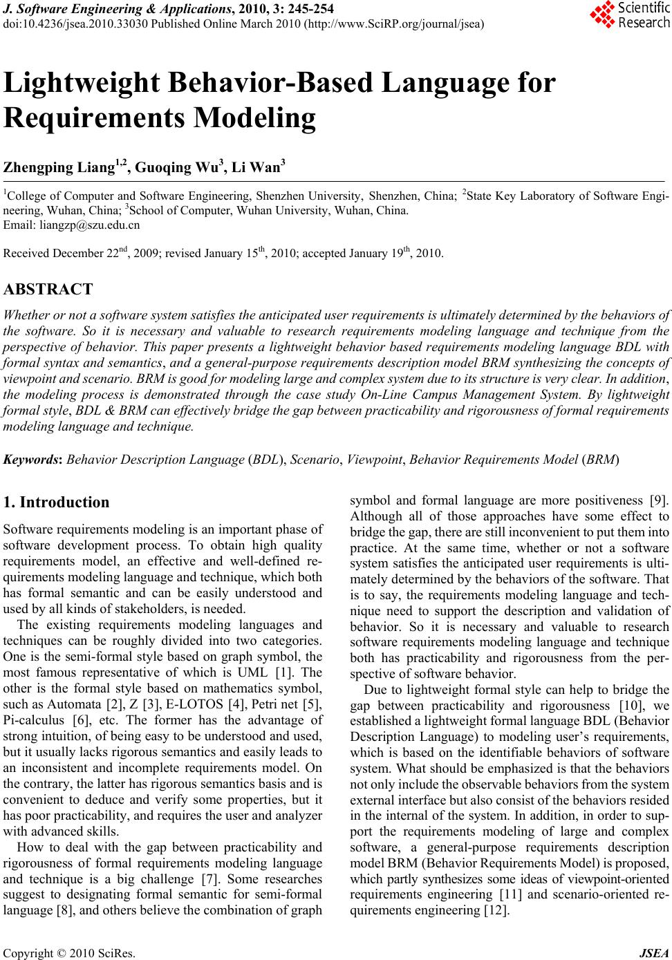 J. Software Engineering & Applications, 2010, 3: 245-254 doi:10.4236/jsea.2010.33030 Published Online March 2010 (http://www.SciRP.org/journal/jsea) Copyright © 2010 SciRes. JSEA 245 Lightweight Behavior-Based Language for Requirements Modeling Zhengping Liang1,2, Guoqing Wu3, Li Wan3 1College of Computer and Software Engineering, Shenzhen University, Shenzhen, China; 2State Key Laboratory of Software Engi- neering, Wuhan, China; 3School of Computer, Wuhan University, Wuhan, China. Email: liangzp@szu.edu.cn Received December 22nd, 2009; revised January 15th, 2010; accepted January 19th, 2010. ABSTRACT Whether or not a software system satisfies the anticipated user requirements is ultimately determined by the behaviors of the software. So it is necessary and valuable to research requirements modeling language and technique from the perspective of behavior. This paper presents a lightweight behavior based requirements modeling language BDL with formal syntax and semantics, and a general-purpose requirements description model BRM synthesizing the concepts of viewpoint and scenario. BRM is good for modeling large and complex system due to its structure is very clear. In addition, the modeling process is demonstrated through the case study On-Line Campus Management System. By lightweight formal style, BDL & BRM can effectively bridge the gap between practicability and rigorousness of formal requirements modeling language and technique. Keywords: Behavior Description Language (BDL), Scenario, Viewpoint, Behavior Requirements Model (BRM) 1. Introduction Software requirements modeling is an important phase of software development process. To obtain high quality requirements model, an effective and well-defined re- quirements modeling language and technique, which both has formal semantic and can be easily understood and used by all kinds of stakeholders, is needed. The existing requirements modeling languages and techniques can be roughly divided into two categories. One is the semi-formal style based on graph symbol, the most famous representative of which is UML [1]. The other is the formal style based on mathematics symbol, such as Automata [2], Z [3], E-LOTOS [4], Petri net [5], Pi-calculus [6], etc. The former has the advantage of strong intuition, of being easy to be understood and used, but it usually lacks rigorous semantics and easily leads to an inconsistent and incomplete requirements model. On the contrary, the latter has rigorous semantics basis and is convenient to deduce and verify some properties, but it has poor practicability, and requires the user and analyzer with advanced skills. How to deal with the gap between practicability and rigorousness of formal requirements modeling language and technique is a big challenge [7]. Some researches suggest to designating formal semantic for semi-formal language [8], and others believe the combination of graph symbol and formal language are more positiveness [9]. Although all of those approaches have some effect to bridge the gap, there are still inconvenient to put them into practice. At the same time, whether or not a software system satisfies the anticipated user requirements is ulti- mately determined by the behaviors of the software. That is to say, the requirements modeling language and tech- nique need to support the description and validation of behavior. So it is necessary and valuable to research software requirements modeling language and technique both has practicability and rigorousness from the per- spective of software behavior. Due to lightweight formal style can help to bridge the gap between practicability and rigorousness [10], we established a lightweight formal language BDL (Behavior Description Language) to modeling user’s requirements, which is based on the identifiable behaviors of software system. What should be emphasized is that the behaviors not only include the observable behaviors from the system external interface but also consist of the behaviors resided in the internal of the system. In addition, in order to sup- port the requirements modeling of large and complex software, a general-purpose requirements description model BRM (Behavior Requirements Model) is proposed, which partly synthesizes some ideas of viewpoint-oriented requirements engineering [11] and scenario-oriented re- quirements engineering [12]. 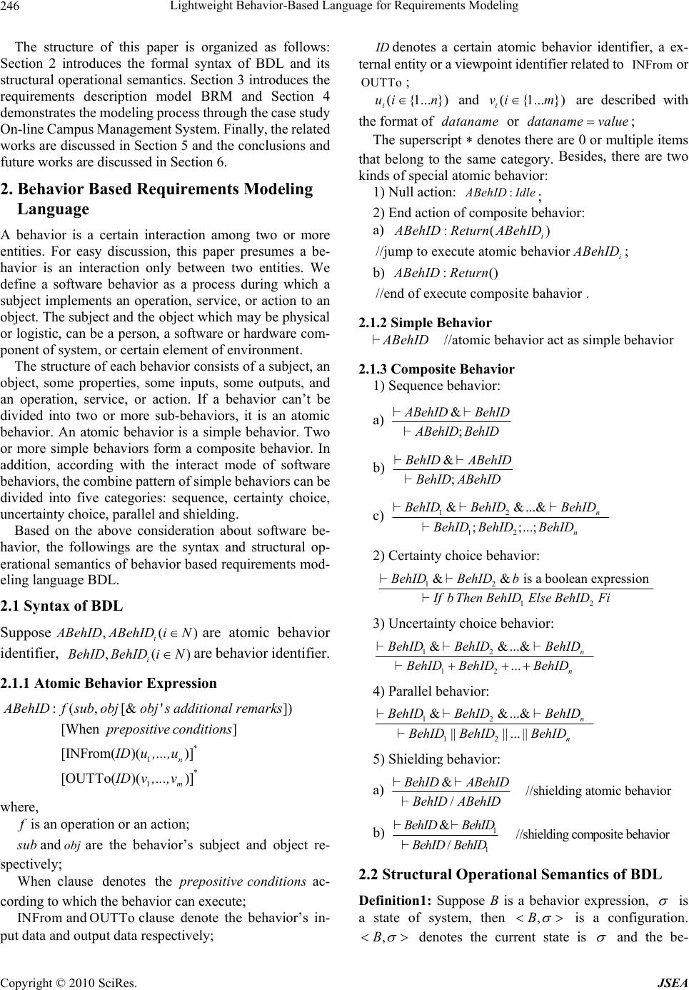 Lightweight Behavior-Based Language for Requirements Modeling 246 The structure of this paper is organized as follows: Section 2 introduces the formal syntax of BDL and its structural operational semantics. Section 3 introduces the requirements description model BRM and Section 4 demonstrates the modeling process through the case study On-line Campus Management System. Finally, the related works are discussed in Section 5 and the conclusions and future works are discussed in Section 6. 2. Behavior Based Requirements Modeling Language A behavior is a certain interaction among two or more entities. For easy discussion, this paper presumes a be- havior is an interaction only between two entities. We define a software behavior as a process during which a subject implements an operation, service, or action to an object. The subject and the object which may be physical or logistic, can be a person, a software or hardware com- ponent of system, or certain element of environment. The structure of each behavior consists of a subject, an object, some properties, some inputs, some outputs, and an operation, service, or action. If a behavior can’t be divided into two or more sub-behaviors, it is an atomic behavior. An atomic behavior is a simple behavior. Two or more simple behaviors form a composite behavior. In addition, according with the interact mode of software behaviors, the combine pattern of simple behaviors can be divided into five categories: sequence, certainty choice, uncertainty choice, parallel and shielding. Based on the above consideration about software be- havior, the followings are the syntax and structural op- erational semantics of behavior based requirements mod- eling language BDL. 2.1 Syntax of BDL Suppose ,( i ABehIDABehIDiN ) are atomic behavior identifier, are behavior identifier. ,( i BehID BehIDiN) 2.1.1 Atomic Behavior Expression * 1 * 1 :(,[& ']) [When ] [INFrom( )()] [OUTTo( )()] n m A BehIDfsubobjobjs additional remarks prepositive conditions IDu ,...,u IDv,...,v where, f is an operation or an action; s ub and are the behavior’s subject and object re- spectively; obj When clause denotes theac- cording to which the behavior can execute; prepositiveconditions INFrom and clause denote the behavior’s in- put data and output data respectively; OUTTo ID UTTo denotes a certain atomic behavior identifier, a ex- ternal entity or a viewpoint identifier related to or ; INFrom O ({1... }) i ui n and ({1... }) i vi m are described with the format of or ; dataname dataname value The superscript denotes there are 0 or multiple items that belong to the same category. Besides, there are two kinds of special atomic behavior: 1) Null action: : A BehIDIdle ; 2) End action of composite behavior: a) :( i ABehIDReturnABehID ) ) //jump to execute atomic behavior i ABehID ; b) :(ABehID Return //end of execute composite bahavior. 2.1.2 Simple Behavior //atomic behavior act as simple behaviorABehID 2.1.3 Composite Behavior 1) Sequence behavior: a) & ; ABehID BehID ABehID BehID b) & ; B ehID ABehID B ehID ABehID c) 12 12 & &...& ; ;...; n n B ehID BehIDBehID BehID BehIDBehID 2) Certainty choice behavior: 12 12 && is a boolean expressionBehIDBehID b Ifb ThenBehIDElseBehIDFi 3) Uncertainty choice behavior: 12 12 & &...& ... n n B ehID BehIDBehID BehID BehIDBehID 4) Parallel behavior: 12 12 & &...& |||| ... || n n B ehID BehIDBehID BehID BehIDBehID 5) Shielding behavior: a) & //shielding atomic behavior / BehID ABehID BehID ABehID b) 1 1 & //shielding composite behavior / BehID BehID BehID BehID 2.2 Structural Operational Semantics of BDL Definition1: Suppose B is a behavior expression, is a state of system, then ,B is a configuration. ,B denotes the current state is and the be- Copyright © 2010 SciRes. JSEA 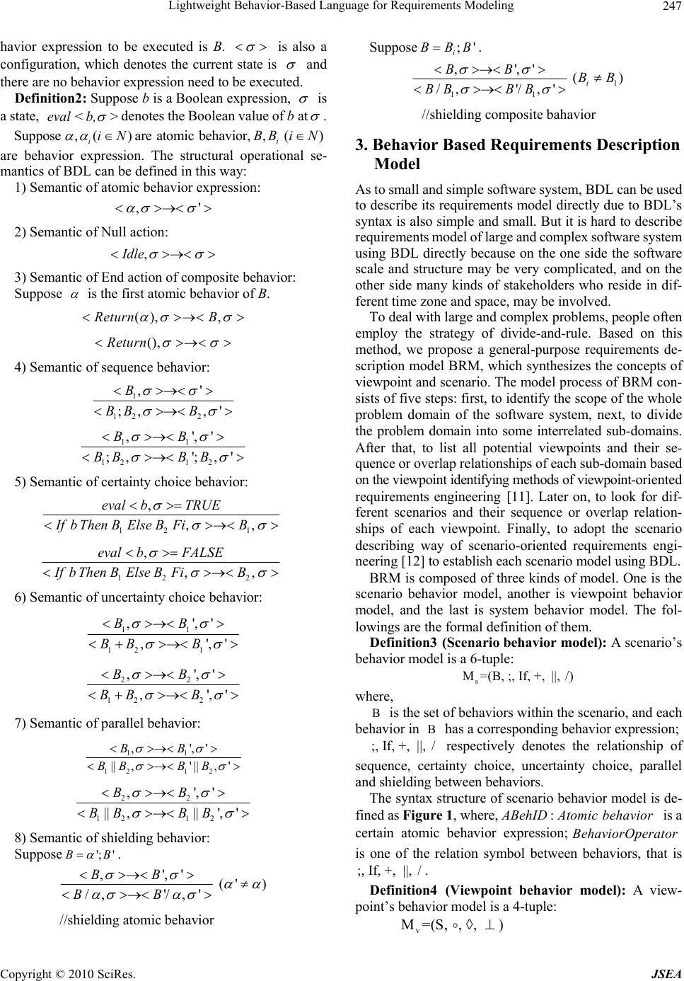 Lightweight Behavior-Based Language for Requirements Modeling247 havior expression to be executed is B. is also a configuration, which denotes the current state is and there are no behavior expression need to be executed. Definition2: Suppose b is a Boolean expression, is a state, eval< b,> denotes the Boolean value of b at . Suppose ,( ) iiN are atomic behavior,,BB i()Ni are behavior expression. The structural operational se- mantics of BDL can be defined in this way: 1) Semantic of atomic behavior expression: ,' 2) Semantic of Null action: ,Idle 3) Semantic of End action of composite behavior: Suppose is the first atomic behavior of B. (), ,Return B (),Return 4) Semantic of sequence behavior: 1 12 2 ,' ;, ,' B BB B 11 121 2 ,',' ' ;, ';, BB BBB B 5) Semantic of certainty choice behavior: 12 1 ,, B ,eval bTRUE IfbThenBElseBFi 12 2 ,, B ,eval bFALSE IfbThenBElseBFi 6) Semantic of uncertainty choice behavior: 11 12 1 ,',' ,' ,' BB BB B 22 12 2 ,',' ,' ,' BB BB B 7) Semantic of parallel behavior: 11 121 2 ,',' ' || ,'|| , BB BBB B 22 12 12 ,',' ' || ,||', BB BB BB 8) Semantic of shielding behavior: Suppose '; ' B B . ,',' /, '/,' BB BB (' ) //shielding atomic behavior Suppose ;' i BBB . 11 ,',' /, '/,' BB BB BB 1 () i BB //shielding composite bahavior 3. Behavior Based Requirements Description Model As to small and simple software system, BDL can be used to describe its requirements model directly due to BDL’s syntax is also simple and small. But it is hard to describe requirements model of large and complex software system using BDL directly because on the one side the software scale and structure may be very complicated, and on the other side many kinds of stakeholders who reside in dif- ferent time zone and space, may be involved. To deal with large and complex problems, people often employ the strategy of divide-and-rule. Based on this method, we propose a general-purpose requirements de- scription model BRM, which synthesizes the concepts of viewpoint and scenario. The model process of BRM con- sists of five steps: first, to identify the scope of the whole problem domain of the software system, next, to divide the problem domain into some interrelated sub-domains. After that, to list all potential viewpoints and their se- quence or overlap relationships of each sub-domain based on the viewpoint identifying methods of viewpoint-oriented requirements engineering [11]. Later on, to look for dif- ferent scenarios and their sequence or overlap relation- ships of each viewpoint. Finally, to adopt the scenario describing way of scenario-oriented requirements engi- neering [12] to establish each scenario model using BDL. BRM is composed of three kinds of model. One is the scenario behavior model, another is viewpoint behavior model, and the last is system behavior model. The fol- lowings are the formal definition of them. Definition3 (Scenario behavior model): A scenario’s behavior model is a 6-tuple: s M=(B, ;, If, +, ||, /) where, B is the set of behaviors within the scenario, and each behavior in has a corresponding behavior expression; B ;, If, +, ||, / respectively denotes the relationship of sequence, certainty choice, uncertainty choice, parallel and shielding between behaviors. The syntax structure of scenario behavior model is de- fined as Figure 1, where, is a certain atomic behavior expression; is one of the relation symbol between behaviors, that is . : ABehIDAtomic behavior BehaviorOperator ;, If, +, ||, / Definition4 (Viewpoint behavior model): A view- point’s behavior model is a 4-tuple: v M=(S, , , ) Copyright © 2010 SciRes. JSEA 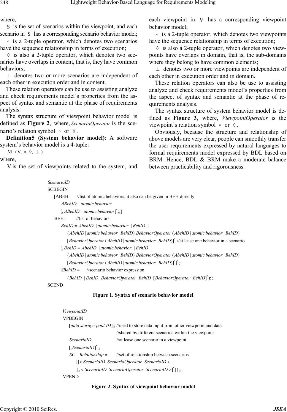 Lightweight Behavior-Based Language for Requirements Modeling Copyright © 2010 SciRes. JSEA 248 where, each viewpoint in has a corresponding viewpoint behavior model; V S is the set of scenarios within the viewpoint, and each scenario in has a corresponding scenario behavior model; S is a 2-tuple operator, which denotes two viewpoints have the sequence relationship in terms of execution; is a 2-tuple operator, which denotes two scenarios have the sequence relationship in terms of execution; is also a 2-tuple operator, which denotes two view- points have overlaps in domain, that is, the sub-domains where they belong to have common elements; is also a 2-tuple operator, which denotes two sce- narios have overlaps in content, that is, they have common behaviors; denotes two or more viewpoints are independent of each other in execution order and in domain. denotes two or more scenarios are independent of each other in execution order and in content. These relation operators can also be use to assisting analyze and check requirements model’s properties from the aspect of syntax and semantic at the phase of re- quirements analysis. These relation operators can be use to assisting analyze and check requirements model’s properties from the as- pect of syntax and semantic at the phase of requirements analysis. The syntax structure of system behavior model is de- fined as Figure 3, where, ViewpointOperator is the viewpoint’s relation symbol or . The syntax structure of viewpoint behavior model is defined as Figure 2, where,is the sce- nario’s relation symbol or ScenarioOperator . Obviously, because the structure and relationship of above models are very clear, people can smoothly transfer the user requirements expressed by natural languages to formal requirements model expressed by BDL based on BRM. Hence, BDL & BRM make a moderate balance between practicability and rigorousness. Definition5 (System behavior model): A software system’s behavior model is a 4-tuple: M=(V, , , ) where, Vis the set of viewpoints related to the system, and * SCBEGIN [ABEH: //list of atomic behaviors, it also can be given in BEH directly : [,: ];;] BEH: //list of behaviors | ScenarioID ABehIDatomic behavior ABehIDatomic behavior BehIDAbehID atomic b * | | (||) (||) [(||)] //at lease one behavior in a scenario [, ehavior BehID AbehID atomic behavior BehIDBehaviorOperator AbehID atomic behavior BehID BehaviorOperator AbehID atomic behavior BehID BehID Ab ** | | | (||) (||) [(||)]];; //scenario behav ehID atomic behavior BehID AbehID atomic behavior BehIDBehaviorOperator AbehID atomic behavior BehID BehaviorOperator AbehID atomic behavior BehID SBehID * ior expression ( | [ ]);; SCEND BehID BehIDBehaviorOperator BehID BehaviorOperator BehID Figure 1. Syntax of scenario behavior model VPBEGIN [];; //used to store data input from other viewpoint and data //shared by different scenarios within the viewpoint ViewpointID data storage pool ID ScenarioID * //at lease one scenario in a viewpoint [,];; _ //set of relationship between scenarios {[ [, ScenarioID SC Relationship ScenarioID ScenarioOperator ScenarioID ScenarioID Sce * ]]};; VPEND narioOperator ScenarioID Figure 2. Syntax of viewpoint behavior model 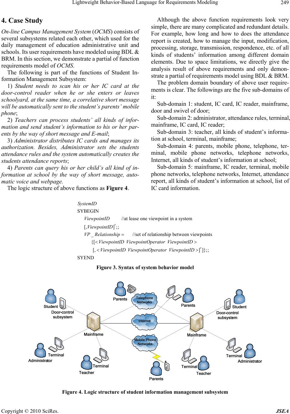 Lightweight Behavior-Based Language for Requirements Modeling 249 4. Case Study On-line Campus Management System (OCMS) consists of several subsystems related each other, which used for the daily management of education administrative unit and schools. Its user requirements have modeled using BDL & BRM. In this section, we demonstrate a partial of function requirements model of OCMS. The following is part of the functions of Student In- formation Management Subsystem: 1) Student needs to scan his or her IC card at the door-control reader when he or she enters or leaves schoolyard, at the same time, a correlative short message will be automatically sent to the student’s parents’ mobile phone; 2) Teachers can process students’ all kinds of infor- mation and send student’s information to his or her par- ents by the way of short message and E-mail; 3) Administrator distributes IC cards and manages its authorization. Besides, Administrator sets the students attendance rules and the system automatically creates the students attendance reports; 4) Parents can query his or her child’s all kind of in- formation at school by the way of short message, auto- matic voice and webpage. The logic structure of above functions as Figure 4. Although the above function requirements look very simple, there are many complicated and redundant details. For example, how long and how to does the attendance report is created, how to manage the input, modification, processing, storage, transmission, respondence, etc. of all kinds of students’ information among different domain elements. Due to space limitations, we directly give the analysis result of above requirements and only demon- strate a partial of requirements model using BDL & BRM. The problem domain boundary of above user require- ments is clear. The followings are the five sub-domains of it: Sub-domain 1: student, IC card, IC reader, mainframe, door and swivel of door; Sub-domain 2: administrator, attendance rules, terminal, mainframe, IC card, IC reader; Sub-domain 3: teacher, all kinds of student’s informa- tion at school, terminal, mainframe; Sub-domain 4: parents, mobile phone, telephone, ter- minal, mobile phone networks, telephone networks, Internet, all kinds of student’s information at school; Sub-domain 5: mainframe, IC reader, terminal, mobile phone networks, telephone networks, Internet, attendance report, all kinds of student’s information at school, list of IC card information. * SYBEGIN //at lease one viewpoint in a system [,] ;; _ //set of relationship between viewpoints {[ SystemID ViewpointID ViewpointID VP Relationship ViewpointID ViewpointOperator ViewpointI * [,]]};; SYEND D ViewpointID ViewpointOperator ViewpointID Figure 3. Syntax of system behavior model Figure 4. Logic structure of student information management subsystem Copyright © 2010 SciRes. JSEA 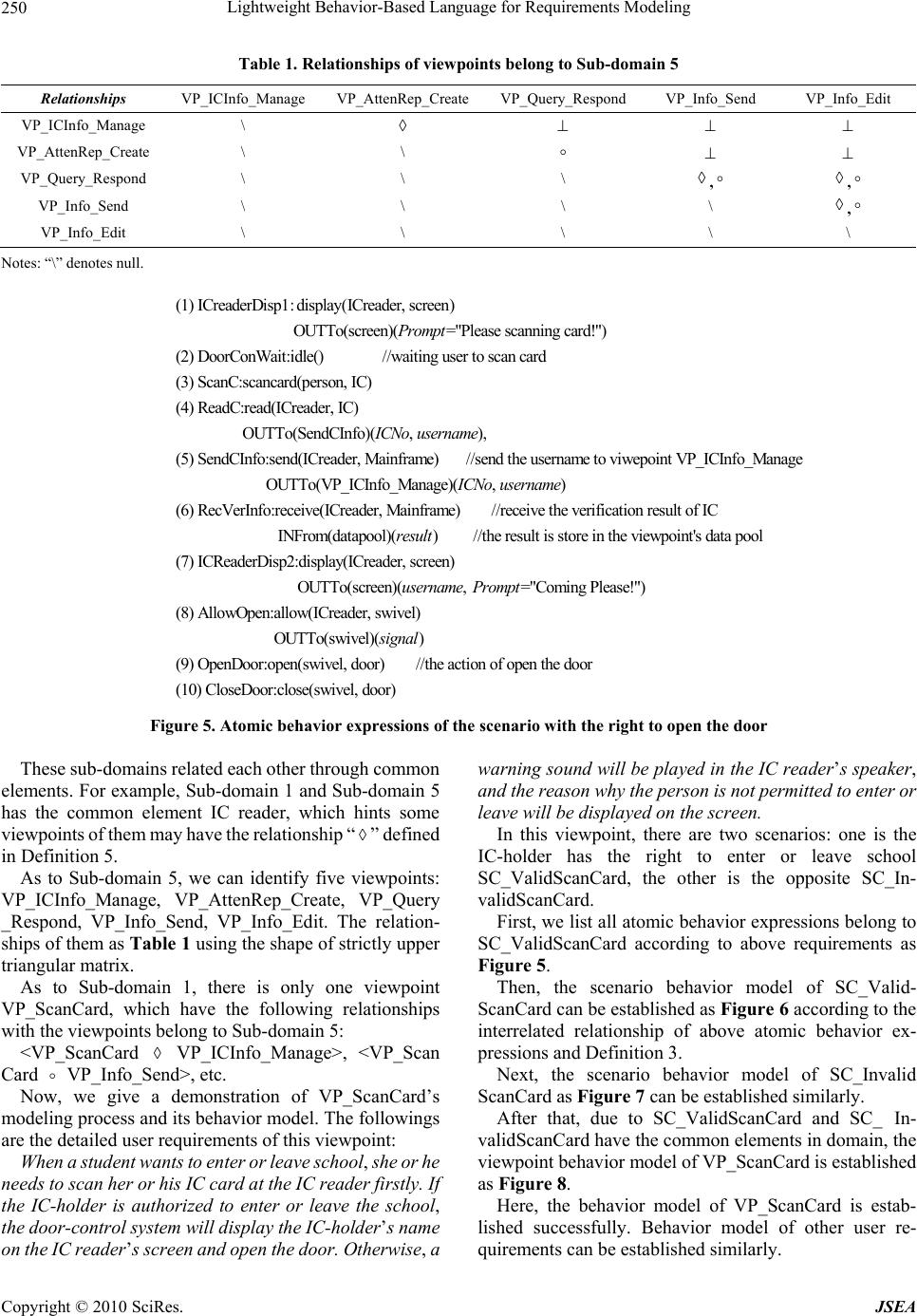 Lightweight Behavior-Based Language for Requirements Modeling 250 Table 1. Relationships of viewpoints belong to Sub-domain 5 Relationships VP_ICInfo_Manage VP_AttenRep_Create VP_Query_Respond VP_Info_Send VP_Info_Edit VP_ICInfo_Manage \ VP_AttenRep_Create \ \ VP_Query_Respond \ \ \ , , VP_Info_Send \ \ \ \ , VP_Info_Edit \ \ \ \ \ Notes: “\” denotes null. (1) ICreaderDisp1:display(ICreader, screen) OUTTo(screen)(="Please scanning card!") (2) DoorConWait:idle() //waiting user to scan card (3) ScanC:scancard Prompt (person, IC) (4) ReadC:read(ICreader, IC) OUTTo(SendCInfo)(, ), (5) SendCInfo:send(ICreader, Mainframe) //send the username to viwepoint VP_ICInfo_Manage ICNousername OUTTo(VP_ICInfo_Manage)(, ) (6) RecVerInfo:receive(ICreader, Mainframe) //receive the verification result of IC INFrom(datapool)() //th ICNo username result e result is store in the viewpoint's data pool (7) ICReaderDisp2:display(ICreader, screen) OUTTo(screen)(, ="Coming Please!") (8) AllowOpen:allow(ICreader, sw username Prompt ivel) OUTTo(swivel)() (9) OpenDoor:open(swivel, door) //the action of open the door (10) CloseDoor:close(swivel, door) signal Figure 5. Atomic behavior expressions of the scenario with the right to open the door These sub-domains related each other through common elements. For example, Sub-domain 1 and Sub-domain 5 has the common element IC reader, which hints some viewpoints of them may have the relationship “” defined in Definition 5. As to Sub-domain 5, we can identify five viewpoints: VP_ICInfo_Manage, VP_AttenRep_Create, VP_Query _Respond, VP_Info_Send, VP_Info_Edit. The relation- ships of them as Table 1 using the shape of strictly upper triangular matrix. As to Sub-domain 1, there is only one viewpoint VP_ScanCard, which have the following relationships with the viewpoints belong to Sub-domain 5: <VP_ScanCard VP_ICInfo_Manage>, <VP_Scan Card VP_Info_Send>, etc. Now, we give a demonstration of VP_ScanCard’s modeling process and its behavior model. The followings are the detailed user requirements of this viewpoint: When a student wants to enter or leave school, she or he needs to scan her or his IC card at the IC reader firstly. If the IC-holder is authorized to enter or leave the school, the door-control system will display the IC-holder’s name on the IC reader’s screen and open the door. Otherwise, a warning sound will be played in the IC reader’s speaker, and the reason why the person is not permitted to enter or leave will be displayed on the screen. In this viewpoint, there are two scenarios: one is the IC-holder has the right to enter or leave school SC_ValidScanCard, the other is the opposite SC_In- validScanCard. First, we list all atomic behavior expressions belong to SC_ValidScanCard according to above requirements as Figure 5. Then, the scenario behavior model of SC_Valid- ScanCard can be established as Figure 6 according to the interrelated relationship of above atomic behavior ex- pressions and Definition 3. Next, the scenario behavior model of SC_Invalid ScanCard as Figure 7 can be established similarly. After that, due to SC_ValidScanCard and SC_ In- validScanCard have the common elements in domain, the viewpoint behavior model of VP_ScanCard is established as Figure 8. Here, the behavior model of VP_ScanCard is estab- lished successfully. Behavior model of other user re- quirements can be established similarly. Copyright © 2010 SciRes. JSEA 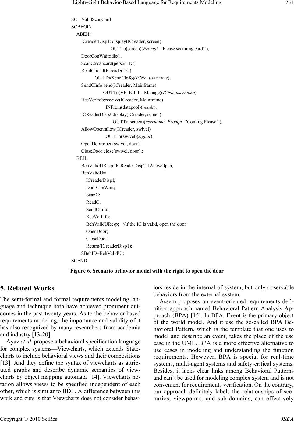 Lightweight Behavior-Based Language for Requirements Modeling 251 SC _ValidScanCard SCBEGIN ABEH: ICreaderDisp1:display(ICreader, screen) OUTTo(screen)(="Please scanning card!"), DoorConWait:idle(), ScanC:sc Prompt ancard(person, IC), ReadC:read(ICreader, IC) OUTTo(SendCInfo)(, ), SendCInfo:send(ICreader, Mainframe) OUTTo(VP_ICInfo_Manage)( ICNo username ICNo , ), RecVerInfo:receive(ICreader, Mainframe) INFrom(datapool)(), ICReaderDisp2:display(ICreader, screen) OUTTo(s username result creen)(, ="Coming Please!"), AllowOpen:allow(ICreader, swivel) OUTTo(swivel)(), OpenDoor:open(swivel, door), CloseDoor:close(swivel, username Prompt signal door);; BEH: BehValidUResp=ICReaderDisp2AllowOpen, BehValidU= ICreaderDisp1; DoorConWait; ScanC; ReadC; SendCInfo; RecVerInfo; BehValidUResp; //if the IC is valid, open the door OpenDoor; CloseDoor; Return(ICreaderDisp1);; SBehID=BehValidU;; SCEND Figure 6. Scenario behavior model with the right to open the door 5. Related Works The semi-formal and formal requirements modeling lan- guage and technique both have achieved prominent out- comes in the past twenty years. As to the behavior based requirements modeling, the importance and validity of it has also recognized by many researchers from academia and industry [13-20]. Ayaz et al. propose a behavioral specification language for complex systems—Viewcharts, which extends State- charts to include behavioral views and their compositions [13]. And they define the syntax of viewcharts as attrib- uted graphs and describe dynamic semantics of view- charts by object mapping automata [14]. Viewcharts no- tation allows views to be specified independent of each other, which is similar to BDL. A difference between this work and ours is that Viewcharts does not consider behav- iors reside in the internal of system, but only observable behaviors from the external system. Assem proposes an event-oriented requirements defi- nition approach named Behavioral Pattern Analysis Ap- proach (BPA) [15]. In BPA, Event is the primary object of the world model. And it use the so-called BPA Be- havioral Pattern, which is the template that one uses to model and describe an event, takes the place of the use case in the UML. BPA is a more effective alternative to use cases in modeling and understanding the function requirements. However, BPA is special for real-time systems, multi-agent systems and safety-critical systems. Besides, it lacks clear links among Behavioral Patterns and can’t be used for modeling complex system and is not convenient for requirements verification. On the contrary, our approach definitely labels the relationships of sce- narios, viewpoints, and sub-domains, can effectively Copyright © 2010 SciRes. JSEA 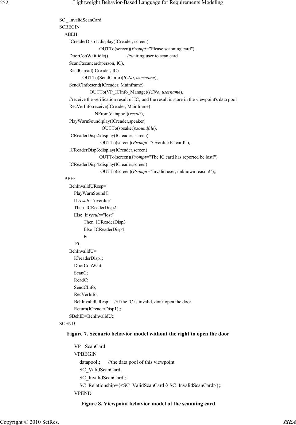 Lightweight Behavior-Based Language for Requirements Modeling 252 SC _InvalidScanCard SCBEGIN ABEH: ICreaderDisp1:display(ICreader, screen) OUTTo(screen)(="Please scanning card"), DoorConWait:idle(), Prompt //waiting user to scan card ScanC:scancard(person, IC), ReadC:read(ICreader, IC) OUTTo(SendCInfo)(, ), SendCInfo:send(ICreader, Mainframe) ICNo username OUTTo(VP_ICInfo_Manage)(, ), //receive the verification result of IC, and the result is store in the viewpoint's data pool RecVerInfo:receive(ICreader, Mainfra ICNo username me) INFrom(datapool)(), PlayWarnSound:play(ICreader,speaker) OUTTo(speaker)(), ICReaderDisp2:display(ICreade result soundfile r, screen) OUTTo(screen)(="Overdue IC card!"), ICReaderDisp3:display(ICreader,screen) OUTTo(screen)(="The IC card ha Prompt Prompt s reported be lost!"), ICReaderDisp4:display(ICreader,screen) OUTTo(screen)(="Invalid user, unknown reason!");; BEH: BehInvalidUResp= Prompt PlayWarnSound If ="overdue" Then ICReaderDisp2 Else If ="lost" Then ICReaderDisp3 Else ICReaderDisp4 result result Fi Fi, BehInvalidU= ICreaderDisp1; DoorConWait; ScanC; ReadC; SendCInfo; RecVerInfo; BehInvalidUResp; //if the IC is invalid, don't open the door Return(ICreaderDisp1);; SBehID=BehInvalidU;; SCEND Figure 7. Scenario behavior model without the right to open the door VP _ ScanCard VPBEGIN datapool;; //the data pool of this viewpoint SC_ValidScanCard, SC_InvalidScanCard;; SC_Relationship={<SC_ValidScanCard SC_InvalidScanCard>};; VPEND Figure 8. Viewpoint behavior model of the scanning card Copyright © 2010 SciRes. JSEA  Lightweight Behavior-Based Language for Requirements Modeling 253 support the modeling and verification of large and com- plex system. Khairuddin et al. propose a requirements notation RNSMA and a behavioral approach to specify interactive multimedia applications [16]. RNSMA is based on Petri Net, but its semantics are extended to support reactive systems. In RNSMA, transitions due to events are subdi- vided into automatic, user and clock. The transitions due to tasks to be done are subdivided into animate, image, sound, text and video. RNSMA uses an extremely simple syntax, which can be read even by novices as a form of pseudo-code. Compared with RNSMA, our work can support general-purpose requirements modeling, not spe- cial for stand-alone multimedia applications. UML is a general-purpose and most famous modeling language for software engineering, which is standardized by OMG [1]. Requirements modeling manner in UML consists of the use case diagram, sequence diagram, state diagram and activity diagram. UML provides standard notation for modeling software analysis and design. But a common and fair criticism of UML is that it is gratuitously large and complex, imprecise semantics, and a dysfunc- tional diagram interoperability standard (XMI). As an- other OMG standard, SysML acts as a general-purpose modeling language for systems engineering applications [17]. SysML is based on UML, and it reduces UML’s size and software bias while extending its semantic to model requirements and parametric constraints. These capabili- ties are essential to support requirements engineering and performance analysis. Besides, there are some researches based on UML and SysML. Luigi et al. propose combining problem frames and UML to describe software requirements in order to improve the linguistic support for problem frames and the UML development practice by introducing the problem frames approach [18]. Pietro et al. propose the integration of SysML and problem frames by presenting how a set of well known problem frames can be represented by means of SysML [19]. Atle et al. propose to extend UML se- quence diagrams to model trust-dependent behavior with the aim to support risk analysis [20]. All of these re- searches are good for the enhancement of behavior mod- eling. In addition, there are many kinds of formal languages and techniques for requirements modeling, especially for behavior requirements. Most of them are based on state or event. Some are standardized by different international organization, such as Z [3], E-LOTOS [4]. Others may be very famous in industry, such as B [21], VDM [22]. Al- though formal languages and techniques have many ad- vantages, it is difficult to put into practices totally. On the contrary, our approach can be easily used to transform natural language requirements to formal requirements model because the syntax of BDL and the structure of BRM are very simple and clear. 6. Conclusions and Future Work Software requirements modeling from the perspective of behavior can not only supports the description and mod- eling of function requirements but also supports the analysis and deduction of non-function requirements. As a lightweight formal requirements description language and model, BDL & BRM can help to smoothly transfer the user requirements expressed by natural languages to formal requirements model expressed by BDL. And the formal model BRM is also good for subsequent require- ments verification and validation. Hence, BDL & BRM can effectively bridge the gap between practicability and rigorousness of formal requirements modeling language and technique. Several completed case studies also testi- fied this kind of feature of BDL & BRM. Currently, we have realized the prototype requirements modeling tool and experimented some case studies. Future works will mainly focus on to define all kinds of re- quirements properties based on BDL&BRM, and to de- sign and implement corresponding automatic analyzing and deducing methods. 7. Acknowledgements This work is supported by the National High Technology Research and Development Program of China under contract 2007AA01Z185, the Open Research Foundation of Chinese State Key Laboratory of Software Engineering under grant SKLSE20080702, and the SZU R/D Fund 200747. REFERENCES [1] Object Management Group, “OMG Unified Modeling Language (OMG UML) Version 2.0,” 2005. [2] J. E. Hopcroft, R. Motwani, and J. D. Ullman, “Introduc- tion to automata theory, languages, and computation,” 2nd Edition, Pearson Education, 2000. [3] “Information technology—Z formal specification nota- tion —Syntax, type system and semantics,” ISO/IEC 13568, 2002. [4] “Information processing systems—Open systems inter- connection—Enhancements to LOTOS—A formal des- cription technique based on the temporal ordering of observational behavior,” ISO/IEC 15437, 2001. [5] J. L. Peterson, “Petri net theory and the modeling of systems,” Prentice Hall, 1981. [6] R. Milner, “Communicating and mobile systems: The Pi-calculus,” Cambridge University Press, 1999. [7] J. P. Bowen and M. G. Hinchey, “Ten commandments of formal methods... ten years later,” IEEE Computer, Vol. 39, No. 1, pp. 40–48, January 2006. [8] J. Kong, K. Zhang, J. Dong, and D. Xu, “Specifying behavioral semantics of UML diagrams through graph transformations,” Journal of Systems and Software, Vol. 82, No. 2, pp. 292–306, April 2009. Copyright © 2010 SciRes. JSEA  Lightweight Behavior-Based Language for Requirements Modeling 254 [9] C. Attiogbe, P. Poizat, and G. Salaun, “A formal and tool-equipped approach for the integration of state diagrams and formal datatypes,” IEEE Transactions on Software Engineering, Vol. 33, No. 3, pp. 157–170, March 2007. [10] M. Hinchey, M. Jackson, and P. Cousot, J. P. Bowen, and T. Margeria, “Software engineering and formal methods,” Communications of the ACM, Vol. 51, No. 9, pp. 54–59, September 2008. [11] G. Kotonya and I. Sommerville, “Requirements engineer- ing with viewpoints,” Software Engineering Journal, Vol. 11, No. 1, pp. 5–18, January 1996. [12] A. Sutcliffe, “Scenario-based requirements engineering,” in Proceedings of the 11th IEEE International Conference on Requirements Engineering, Monterey, California, pp. 320–329, September 2003. [13] A. Isazadeh, D. A. Lamb, and G. H. MacEwen, “View- charts: A behavioral specification language for complex systems,” Proceedings of the 4th International Workshop on Parallel and Distributed Real-Time Systems, Honolulu, Hawaii, pp. 208–215, April 1996. [14] A. Isazadeh and J. Karimpour, “Viewcharts: Syntax and semantic,” Informatica, Vol. 19, No. 3, pp. 345–362, March 2008. [15] A. E. Ansary, “Requirements definition of real-time system using the Behavioral Patterns Analysis (BPA) approach: The elevator control system,” Proceedings of the Second International Conference on Software and Data Technologies, Barcelona, pp. 371–377, July 2007. [16] K. Hashim and J. Yousoff, “A behavioral requirements specification approach for interactive multimedia appli- cations,” Proceedings of the 19th Australian Conference on Software Engineering, Perth, West Australia, pp. 696–699, March 2008. [17] “OMG Systems Modeling Language (OMG SysML) Version 1.1,” Object Management Group, 2008. [18] L. Lavazza and V. D. Bianco, “Combining problem frames and UML in the description of software require- ments,” In: B. Luciano, H. Reiko, Ed., Lecture Notes in Computer Science, Vol. 3922, pp. 199–213, 2006. [19] P. Colombo, V. del Bianco, and L. Lavazza, “Towards the integration of sysml and problem frames,” Proceedings of the 3rd International Workshop on Applications and Advances of Problem Frames, Leipzig, pp. 1–8, May 2008. [20] A. Refsdal and K. Stolen, “Extending UML sequence diagrams to model trust-dependent behavior with the aim to support risk analysis,” Science of Computer Program- ming, Vol. 74, No. 1–2, pp. 34–42, January 2008. [21] S. Schenider, “The B-method: An introduction,” Palgrave, 2001. [22] C. B. Jones, “Systematic software development using VDM,” Prentice Hall, 1990. Copyright © 2010 SciRes. JSEA |