Journal of Modern Physics
Vol.3 No.9(2012), Article ID:22616,7 pages DOI:10.4236/jmp.2012.39130
Dependence of Plasma Parameters on Plate Separation and Filament Location in a Double Plasma Device
1Centre of Plasma Physics—Institute for Plasma Research, Tepesia, India
2ITER-India, Institute for Plasma Research, Gandhinagar, India
Email: *monojitc@yahoo.com
Received June 29, 2012; revised August 2, 2012; accepted August 11, 2012
Keywords: Filament Location; Plasma Parameters; Double Plasma Device
ABSTRACT
A pair of stainless steel (ss) plates separates the source and target regions of a double plasma device. Two sets of tungsten filaments, placed at different distances from the ss plates, are then used to produce plasma alternately and the plasma parameters in the source and target regions for different discharge voltage, discharge current and plate separation are measured using Langmuir probes. It is found that plasma density and electron temperature are considerably affected and respond differently to changes in the plate separations and the position of the filaments.
1. Introduction
Amongst the plasma parameters, electron temperature (Te) and plasma density (ne) are considerably important because many plasma processes are influenced by even subtle changes in their magnitudes. As many plasma applications are also dependent on them therefore it has always been the effort of researchers to find ways to control these two parameters effectively. Alexeff and Jones [1] were among the earlier researchers who demonstrated the way to reduce the electron temperature. MacKenzie et al. [2] performed an experiment and showed how to increase the electron temperature. Using a grounded plate and by changing its position in a multi-dipole capacitively coupled RF plasma, Hershkowitz et al. [3] studied the change in the electron temperature and plasma potential. By using pins in a hollow cathode discharge, Sato et al. [4] showed how the electron temperature could be controlled. Kato et al. [5,6] used a grid and also slits of different sizes to effectively regulate the electron temperature and plasma density.
Due to their versatility, magnetic multipole devices have been used from as early as 1975 onwards to conduct basic studies in plasma [7]. The conditions which multipole devices have the capability to produce are favorable for conducting various basic studies. They are capable of producing quiescent plasma with magnitudes of plasma density and temperature that are found in many naturally occurring plasma systems and man made plasma devices. By using a grid between two multipole magnetic cages, the entire system can be divided up into two regions called the source region, where plasma is produced, and the target region, to which plasma diffuses after passing through the grid. As plasma can be produced in both the source and target regions hence the name “double plasma device”. Depending on the nature of the experiment and purpose of investigation, plasma can be produced in only the source region and after passing through a meshed stainless steel grid or a magnetic filter field, placed between the source and target regions, it can flow to the target region. Mishra et al. used a meshed grid to study the role of energetic electrons in controlling diffused plasma parameters in a DP device [8]. In another study the magnetic cages as well as the grid were biased to see the changes in the plasma conditions [9].
In a new experimental investigation we have changed the spacing of the stainless steel (ss) plates placed between the source and target regions of the double plasma device and also used two sets of filaments placed at different distances from the plates to see their effect on the electron temperature and plasma density in both the source as well as target regions. In a fusion device, neutral beam injection heating is used along with other heating methods. Neutral beam injection (NBI) utilizes energetic neutral particles to heat fusion plasma. Energetic neutral particles are produced in NBIs by converting energetic ions through charge exchange collisions. Ions (positive or negative) are produced in an ion source (positive ion source or negative ion source). In a negative ion source, a transverse magnetic field and bias plate (BP) are placed [10] in front of the plasma grid. The bias plate is in the form of a plate like structure and it is immersed in plasma. It is electrically connected to the plasma chamber and isolated from the plasma grid. The plasma grid is biased positively with respect to the bias plate [11] to reduce the co-extracted electron current in the extracted negative ion beam. The shape of the bias plate is similar to a photo frame and it surrounds the total beam extraction area on the plasma grid [12]. In this manuscript we have studied the influence of the bias plate (stainless steel plate—in this study) on the plasma parameters in the source and target regions, with respect to the filament positions in an arc discharge plasma.
2. Experimental Methods
The sketch of the arrangement used to conduct the experiment is shown in the Figure 1. The experiment is performed in a stainless steel plasma chamber of length 1.1 m and diameter 0.3 m. The two regions namely “Source”, where plasma is produced, and “Target”, where plasma diffuses, contain two full lined cusped magnetic confinement cages both of which are cylindrical in shape and of length 0.32 m each. Fourteen stainless steel channels containing vacuum sealed 0.12 T strontium ferrite magnets are arranged in the form of a cylinder to form each cylindrical cage. Four stainless steel channels filled with 0.12 T strontium ferrite magnets are used to form each end plate of these cages in both the source and target regions. The plasma chamber and the magnetic cages are grounded. Two stainless steel plates are placed between the source and the target magnetic cages. These plates cover the entire space between the chamber walls and the centre where a gap is kept between the two plates through which plasma can diffuse from the source to the target region as shown in Figure 2. The gap between the plates can be varied and it is fixed at three separation distances of 0.15 m, 0.115 m and 0.08 m. In the source region, two sets of tungsten filaments, F1 and F2 (in Figure 1), are placed at 0.125 m and 0.235 m away from the ss plates at the centre of the two magnetic cages. Each set consists of five tungsten filaments of length 0.03 m each and all of them are mounted in the magnetic field free region within the magnetic cage. Based on their distance from the plates, F1 and F2 are respectively called the “near plate” and “far plate” filaments. VD represents the discharge voltage power supply and VF1, VF2 are the filament current power supplies for the near and far plate filaments. A diffusion pump backed by a rotary pump gives a base pressure of 3.04 × 10⁻⁶ Torr in the plasma chamber. By feeding Hydrogen gas the working pressure is fixed at 3.8 × 10⁻⁴ Torr. The filaments, which serve as cathode, are heated from the filament heater power supply which is either VF1 or VF2 as is the requirement. For producing plasma the discharge

Figure 1. Sketch of the experimental setup.
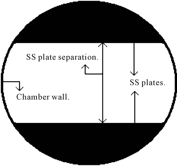
Figure 2. Stainless steel plate arrangement between the source and target regions.
voltage power supply VD is used and the discharge voltage is applied between the filaments and the grounded chamber. Plasma is produced by using the filaments F1 and F2 alternately. By changing the discharge voltage (Vd) from 60 V to 100 V and discharge current (Id) from 0.5 A to 2 A the plasma parameters in the source and the target regions are measured using Langmuir probes LP1 and LP2 which are inserted radially and positioned at the centre of the source and target regions. The cylindrical tungsten probe tip is of length 0.01 m and diameter 0.0001 m. LP1 and LP2, Hiden’s Advanced Espion Langmuir probe system, are used for data collection and analysis.
Before taking the first set of readings, the plate separation between the source and target regions is set at 0.15 m. The discharge voltage Vd is fixed at 60 V and the discharge current Id is varied from 0.5 A to 2 A, in steps of 0.5 A, by changing the filament current for F1 filaments from the filament power supply VF1. In the source region, using the Langmuir probe LP1, I-V characteristic curves at each Id are obtained and the plasma parameters determined. Then the procedure followed for taking the readings at Vd = 60 V is repeated by setting the discharge voltage first at Vd = 80 V and then at Vd = 100 V. The above procedure is repeated for the F1 filaments. Once the readings in the source region are completed, the readings in the target region are then taken with the Langmuir probe LP2 by following the same procedure as in the case of the readings taken in the source region. The plate separation is then decreased to 0.115 m and finally to 0.08 m and the procedure stated above is repeated in both the source and target regions to complete the sets of readings for the three plate separation cases. The readings taken at the three different plate separations for both F1 and F2 filaments and at different discharge conditions are then compared and analyzed.
3. Results and Discussion
For the near plate (F1) and far plate (F2) filaments, in the source region, the change in the electron density ne at various discharge current Id for the three plate separations and at discharge voltage Vd = 80 V is shown in Figure 3. For F2 filaments, ne is highest at plate separation 0.15 m and lowest at 0.08 m separation. In all the cases of plate separation there is a gradual increase in ne with increase in Id. The plates present a loss area for the charged particles of plasma which are produced in the source region and are moving to the target region. When the plate separation distance is decreased from 0.15 m to 0.115 m and then to 0.08 m, the loss area presented by the plates increase from ~250 cm2 to 300 cm2 and then to 360 cm2 and plasma density will fall. This is observed in the plot of Figure 3 where the plasma density is seen to decrease as the plate separation is decreased thereby increasing the plate loss area for the plasma particles. When the near plate (F1) filaments are used then plasma density is found to be highest at plate separation 0.15 m and lowest at 0.08 m separation. ne is found to increase gradually when the discharge current is increased from 0.5 A to 2 A and this change is observed for all the three cases of plate separation. The observations in the source region for the near plate filaments and the reasons for these changes, discussed above are similar to those observed for the far plate filaments in the source region.
In the target region, plasma density is seen to change with discharge current and plate separation for F1 and F2 filaments as shown in the Figure 4. Here, for both F1 and F2 filaments, ne is found to be highest for plate separation 0.15 m and lowest for plate separation 0.08 m. The magnitude of the plasma density (ne) at a particular discharge voltage (Vd) and discharge current (Id) is found to be lower in the target region than in the source region. This is because plasma particles are lost on the plates before they move from the source to the target region. As in the source region, the increase in ne with Id for F2 filaments is found to be regular. As plasma is produced in the source region therefore whatever changes occur in
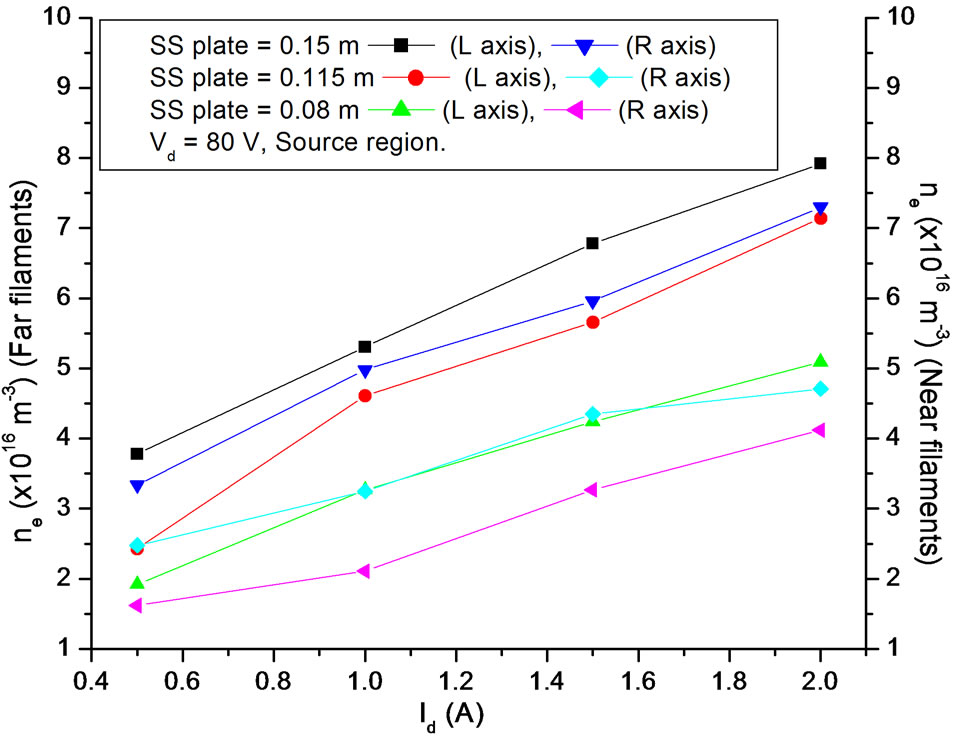
Figure 3. Change of ne with Id for F1 and F2 filaments at Vd = 80 V in source region.
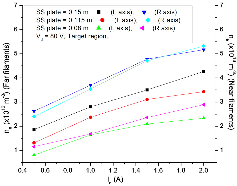
Figure 4. Change of ne with Id for F1 and F2 filaments at Vd = 80 V in target region.
the source region is found to similarly occur in the target region. However, the regularity with which ne is found to change with Id and plate separation in the source region for F1 filaments is not seen in the target region and ne versus Id curves for plate separations 0.15 m and 0.115 m are thus found to almost touch each other. Such cross over for F2 filaments is however not seen to occur. The relation 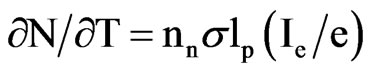 gives the plasma production rate in the source region [13], where N is the total number of electron-ion pairs in the system,
  is the neutral density,
  is the ionization cross section of the neutral gas to be ionized by electrons,
  is the total number of electrons emitted from the filaments per second and
  is the effective primary ionizing electron path length. The production of uniform and quiescent plasma will depend in the manner in which the primary electrons from F1 or F2 filaments ionize the gas in the source region. As F1 and F2 filaments are at different distance from the plate separation therefore the number density and energy of primary electrons moving from the source to the target region through the open space between the plates will also be different. Primary electrons from the filament collide with neutral and plasma particles in the plasma chamber. Since the degree of ionization is low (~10−3) therefore collision of primary electrons with neutrals is dominant. In low pressure plasmas ~3.8 × 10⁻⁴ Torr to ~3.8 × 10⁻⁵ Torr, a primary electron of energy 80 eV, where 80 V is the discharge voltage, will have a mean free path of a few tens of centimeters only. As the F1 filaments are at 0.125 m distance from the plates and the F2 filaments are at 0.235 m away from the plates therefore, on its way towards the plate, a primary electron emitted from the F1 filament will encounter fewer neutral particles than a corresponding primary electron from the F2 filament. As F2 filaments are located near the cusped magnetic field containing end plate of the magnetic cage so when these filaments are used then the primary ionizing electrons from these filaments having longer
  traverses a longer path after making many bounces from the end plate of the magnetic cage and the surrounding surface magnetic field of the cylindrical magnetic cage before reaching the plate separation. This results in the production of uniform and quiet plasma in the source region. Also, as they travel a longer path therefore the primary electrons also lose a greater fraction of their energy due to cooling by inelastic collisions with neutral gas molecules before they are lost to the plate separation or move to the target region. As the F1 (near plate) filaments are nearer to the plate separation therefore some of the primary electrons from the F1 filaments impinging on the plate arrangement will be lost and some will pass directly to the target region and in comparison to the primary electrons from the F2 filaments, a greater fraction of the primary ionizing electrons from the F1 filaments will move directly to the target region. The rest of the primary electrons will contribute to the production of plasma in the source region. The fact that a considerable fraction of primary electrons from F1 filaments move to the target region is evident from the smaller value of the plasma density obtained in the source region when the near plate filaments are used (left axis of Figure 5). Due to the movement of a considerable fraction of the primary electrons to the target region, these energetic electrons also cause ionization of the neutral gas molecules present there. Plasma density in the target region for the F1 filaments is thus found to be higher than the corresponding cases when F2 filaments are used (right axis of Figure 5).
Figure 6 shows the change in electron temperature with discharge current at discharge voltage of 80 V for far plate (F2) and near plate (F1) filaments in the source region. For F2 filaments electron temperature is found to
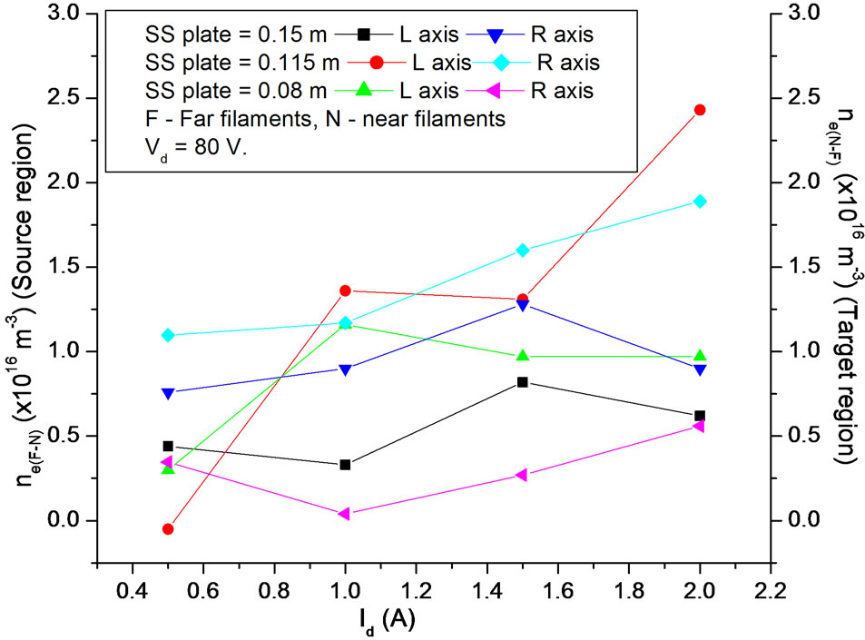
Figure 5. Change of ne(N-F) with Id in target region and ne(F-N) with Id in source region.

Figure 6. Change of Te with Id for F1 and F2 filaments at Vd = 80 V in source region.
be highest for 0.08 m and lowest for 0.15 m plate separation with the values for 0.115 m plate separation falling between the values of the other two. Due to the presence of the plates, some of the primary electrons from the filaments as well as plasma electrons in the source region are lost and some move to the target region directly through the open space present between the plates. When the separation distance becomes narrower then the loss area for the charged particles will increase. It has been found that Te increases with increase in the loss area formed by the plates [3]. As the discharge current is increased from 0.5 A to 2 A in steps of 0.5 A, electron temperature is found to increase. In order to increase the discharge current more primary electrons are injected into plasma by increasing the filament current. As a result the number density of primary electrons in the plasma volume will increase and this will result in an enhancement of the electron temperature. The electron temperature variation in the source region for near plate (F1) filaments, in a similar manner like the far plate filaments, is maximum for 0.08 m plate separation and minimum for 0.15 m plate separation. There is gradual increase of Te with Id. For these observations the same reasoning as in the case of Te variation for the F2 filaments is applicable here. However, electron temperature for near plate (F1) filaments is always found to be more than far plate (F2) filaments. In the source region when F1 filaments are used, the plasma electrons resulting from the inelastic collision of the primary electrons from F1 filaments with gas atoms and molecules will have higher energy as these primary electrons do not undergo many collisions as do their counterparts from F2 filaments.
Figure 7 shows the change in the electron temperature in the target region for F1 and F2 filaments. For F2 filaments Te is found to be minimum for 0.15 m plate separation and maximum for 0.08 m plate separation. The magnitude of Te increases as the discharge current is increased. The changes observed here are similar to those observed in the source region. The Te values are found to be lower than the corresponding Te values in the source region. This is due to the decrease of electron temperature due to collision with neutrals in the target region.
Figure 7 also shows the change of Te with Id for F1 filaments. The manner in which Te varies is found to be similar to the variation of Te for F2 filaments but the magnitude of Te is found to be more than the corresponding Te values for F2 filaments at a particular discharge current and ss plate separation. This indicates that a large number of primary electrons move directly from the source region to the target region so that even after losing energy through inelastic collision with neutrals in the target region their energy is higher than the case when the F2 filaments are used. It is also seen that for both F1 and F2 filaments difference in Te values between the source and target regions is much more at 0.08 m plate separation than at 0.115 m or 0.15 m separation. As plasma production takes place only in the source region therefore with increase in loss area in the ss plates there is fall in movement of electrons from the source region to the target region and there is an overall decrease in energy of the electrons in the target region. The difference in the electron temperature between the source and target region thus increases. This shows that for smaller plate openings between source and target regions the difference in Te will be higher.
The observations on the plasma density and electron temperature at Vd = 80 V are also similarly observed at Vd = 60 V and 100 V. The plots for all the observations have not been given due to the similar nature of the plots as seen at Vd = 80 V. However, as an illustration, plasma density and electron temperature variations with discharge voltage at a discharge current of 1.5 A and various ss plate separations are plotted in Figures 8 to 11. The discharge voltage has been found to differently affect the magnitudes of the plasma density and electron temperature for near and far filaments. For far filaments there is gradual increase in the plasma density with discharge voltage in the source as well as target regions in almost all cases (Figures 8 and 9). For the near plate filaments, plasma density in the source is found to remain almost constant at the various discharge voltages whereas in the target region it shows an increase in magnitude with discharge voltage although not as regularly as the far plate filaments (Figures 8 and 9). In the source region, electron temperature for the far plate filaments is found to remain more or less at the same value with increase in discharge voltage but for the near plate filaments Te shows a slight increase with Vd (Figure 10). In the target region Te for far plate filaments decrease with increase in discharge voltage in almost all the cases and

Figure 7. Change of Te with Id for F1 and F2 filaments at Vd = 80 V in target region.

Figure 8. Change of ne with Vd at Id = 1.5 A in the source region for F1 and F2 filaments.

Figure 9. Change of ne with Vd at Id = 1.5 A in target region for F1 and F2 filaments.
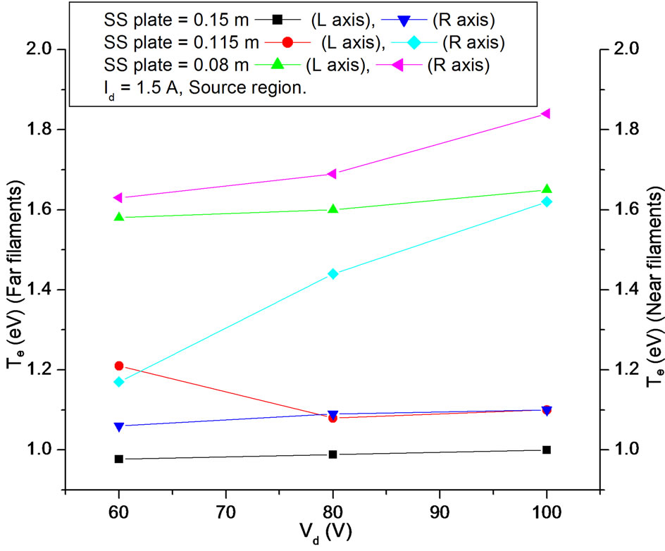
Figure 10. Change of Te with Vd at Id = 1.5 A in source region for F1 and F2 filaments.
for near plate filaments the values are found to remain more or less same and no definite variation is noticed (Figure 11). The effect of discharge voltage is thus not found to follow any particular trend. The magnitude of plasma density and electron temperature do not change much in response to the discharge voltage. This could be due to the selection of the voltage difference of just 20 V above and below the optimum discharge voltage of 80 V for Hydrogen.
4. Conclusions
In conclusion, in the source region of a double plasma device, using filaments placed at different distances with respect to plate separations we have performed an experiment to demonstrate that filament location and plate separations can considerably influence the way in which plasma parameters respond to various experimental configurations. The experimental plots show that in the source region the values of plasma density are higher for far plate filaments than for the near plate filaments. Also, for far plate filaments, the variation of plasma density with discharge current at the different plate separations is found to be much more regular than for near plate filaments. In the target region the plasma density for near plate filaments is higher than for far plate filaments but the change in plasma density with discharge current is more regular for far plate than for near plate filaments. Electron temperature in the source region for near plate filaments is found to be slightly more than for far plate filaments. In the target region electron temperature for near plate filaments is found to be considerably higher than for far plate filaments.
Among the important observations of our experiment is the dependence of the electron density on the position of the filaments and the dependence of the electron temperature on the plate separation between the source and target regions. It has also been found that filaments placed at far distance from the plate separation give better change in the electron density with discharge current. The location of the source region filaments with respect to the plate separation in the double plasma device thus affects the plasma parameters in both the source and target regions.
Plasma density and electron temperature have always aroused interest because their values determine the values of the other parameters in plasma. Many plasma phenomena are also dependent on their magnitudes such as in negative ion sources where the magnitudes of ne and Te in the source and extraction regions are crucial for efficient production of negative ions. Our experiment on the changes in the plasma parameters with filament position, the plate separation, discharge current and discharge
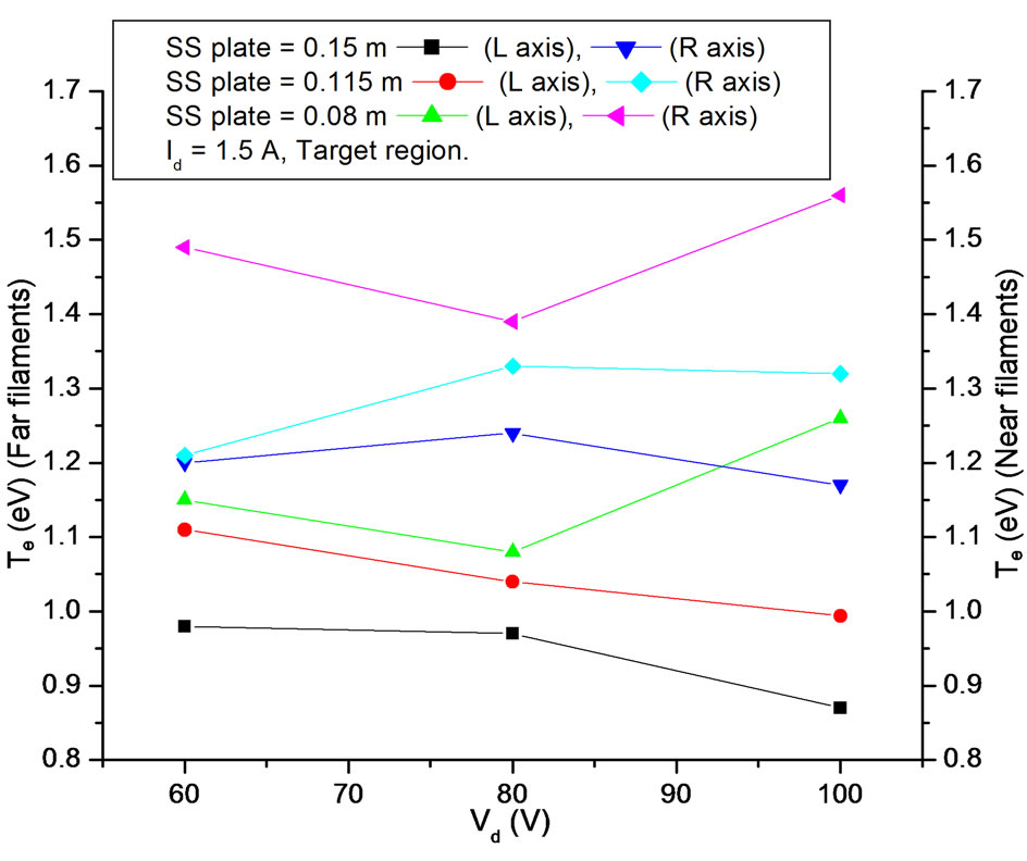
Figure 11. Change of Te with Vd at Id = 1.5 A in target region for F1 and F2 filaments.
voltage has helped us to improve our understanding on the way the experimental configurations should be fixed to obtain the desired results.
5. Acknowledgements
The authors thank the Institute for Plasma Research, Gandhinagar, India, for providing fund under the CPPIPR Collaboration project number 8 to do this work.
REFERENCES
- I. Alexeff and W. D. Jones, “Varying Plasma Electron Temperature in Discharge Tubes by a Simple Auxiliary Electrode,” Applied Physics Letters, Vol. 9, No. 2, 1966, pp. 77-79. doi:10.1063/1.1754650
- K. R. MacKenzie, R. J. Taylor, D. Cohn, E. Ault and H. Ikezi, “Plasma Electron Heating by Absorption of Cold Electrons,” Applied Physics Letters, Vol. 18, No. 12, 1971, pp. 529-530. doi:10.1063/1.1653525
- N. Hershkowitz, M.-H. Cho and J. Pruski, “Mechanical Variation of Plasma Potential, Electron Temperature and Plasma Density,” Plasma Sources Science and Technology, Vol. 1, No. 2, 1992, p. 87. doi:10.1088/0963-0252/1/2/003
- N. Sato, S. Lizuka, T. Koizumi and T. Takada, “ElectronTemperature Control by Movable Pins Installed in a Hollow Cathode for Discharge Plasmas,” Applied Physics Letters, Vol. 62, No. 6, 1993, pp. 567-569. doi:10.1063/1.108913
- K. Kato, S. Lizuka and N. Sato, “Electron-Temperature Control for Plasmas Passing through a Negatively Biased Grid,” Applied Physics Letters, Vol. 65, No. 7, 1994, pp. 816-818. doi:10.1063/1.112240
- K. Kato, T. Shimizu, S. Lizuka and N. Sato, “Electron Temperature Control by Varying Size of Slits Made in a Grid,” Applied Physics Letters, Vol. 76, No. 5, 2000, pp. 547-459. doi:10.1063/1.125814
- K. N. Leung, R. D. Collier, L. B. Marshall, T. N. Gallaher, W. H. Ingham, R. E. Kribel and G. R. Taylor, “Characteristics of a Multidipole Ion Source,” Review of Scientific Instruments, Vol. 49, 1978, p. 321.
- M. K. Mishra, A. Phukan, M. Chakraborty and K. S. Goswami, “Role of High Energetic Electrons in Controlling Diffused Plasma Parameters in a Double Plasma Device,” Physics Letters A, Vol. 365, No. 1-2, 2007, pp. 135-139. doi:10.1016/j.physleta.2006.12.078
- M. K. Mishra, A. Phukan and M. Chakraborty, “Effect of Cathode and Anode Voltage on an Ion Sheath Thickness in a Magnetically Confined Diffusion Plasma,” Contributions to Plasma Physics, Vol. 47, No. 10, 2007, pp. 677- 682. doi:10.1002/ctpp.200710077
- E. Speth, H. D. Falter, P. Franzen, U. Fantz, M. Bandyopadhyay, et al., “Overview of the RF Source Development Programme at IPP Garching,” Nuclear Fusion, Vol. 46, No. 6, 2006, p. S220. doi:10.1088/0029-5515/46/6/S03
- M. Bacal, J. Bruneteau and P. Devynck, “Method for Extracting Volume Produced Negative Ions,” Review of Scientific Instruments, Vol. 59, No. 10, 1988, pp. 2152- 2157. doi:10.1063/1.1139978
- W. W. Kraus, H.-D. Falter, U. Fantz, P. Franzen, B. Heinemann, P. McNeely, R. Riedl and E. Speth, “Long Pulse Large Area Beam Extraction with a RF Driven H(-)/D(-) Source,” Review of Scientific Instruments, Vol. 79, 2008, Article ID: 02C108.
- K. N. Leung, T. Samec and A. Lamm, “Optimization of Permanent Magnet Plasma Confinement,” Physics Letters, Vol. 51A, 1975, p. 490.
NOTES
*Corresponding author.