Smart Grid and Renewable Energy
Vol. 4 No. 1 (2013) , Article ID: 28145 , 11 pages DOI:10.4236/sgre.2013.41015
Towards Implementation of Smart Grid: An Updated Review on Electrical Energy Storage Systems
![]()
1Department of Electrical and Electronic Engineering, Bangladesh University of Engineering and Technology, Dhaka, Bangladesh; 2Department of Electrical and Electronic Engineering, Khulna University of Engineering and Technology, Khulna, Bangladesh; 3Department of Electrical and Electronic Engineering, Stamford University Bangladesh, Dhaka, Bangladesh.
Email: *multan_eee@stamforduniversity.edu.bd
Received November 27th, 2012; revised December 26th, 2012; accepted January 4th, 2012
Keywords: Battery; Distributed Generation; Hybrid Energy Storage Systems; Power Quality; Smart Grid
ABSTRACT
A smart grid will require, to greater or lesser degrees, advanced tools for planning and operation, broadly accepted communications platforms, smart sensors and controls, and real-time pricing. The smart grid has been described as something of an ecosystem with constantly communication, proactive, and virtually self-aware. The use of smart grid has a lot of economical and environmental advantages; however it has a downside of instability and unpredictability introduced by distributed generation (DG) from renewable energy into the public electric systems. Variable energies such as solar and wind power have a lack of stability and to avoid short-term fluctuations in power supplied to the grid, a local storage subsystem could be used to provide higher quality and stability in the fed energy. Energy storage systems (ESSs) would be a facilitator of smart grid deployment and a “small amount” of storage would have a “great impact” on the future power grid. The smart grid, with its various superior communications and control features, would make it possible to integrate the potential application of widely dispersed battery storage systems as well other ESSs. This work deals with a detailed updated review on available ESSs applications in future smart power grids. It also highlights latest projects carried out on different ESSs throughout all around the world.
1. Introduction
The world’s electricity systems face a number of challenges, including aging infrastructure, continuous increase in demand, the integration of growing numbers of variable renewable energy DGs and electric and hybrid electric vehicles, the need to improve the security of power supply, and the need to lower carbon dioxide (CO2) emissions [1-3]. These challenges must be addressed also with regard to each region’s unique technical, economic, and commercial regulatory environment [4]. Smart grid technologies offer ways not just to meet these challenges but also to develop a sustainable energy supply that is more energy efficient and more affordable.
Compared to other industries, our electrical grid has been largely bypassed by technological innovation until relatively recently, owing to the fact that historically it has been heavily regulated and modeled to keep the lights on and costs low. Partly for this reason, its modernization by means of information-technology tools and techniques has been somewhat of a back-burner priority. Like the telecom and internet revolutions that preceded it, technology holds the key to the smart grid and its realization. The smart grid and the technologies embodied within it are an essential set of investments that will help bring our electric grid into the 21st century using megabytes of data to move megawatts of electricity more efficiently, reliably, and affordably [5-9].
The smart grid will:
• Provide power quality for the digital economy;
• Accommodate all generation and storage options;
• Enable new products, services, and markets;
• Optimize asset utilization and operate efficiently;
• Enable active participation by consumers;
• Anticipate and respond to system disturbances;
• Operate resiliently against attack and natural disaster.
Storage is perhaps the most important smart grid advanced component because of its key role in complementing renewable generation. With the proper amount and type of storage broadly deployed and optimally controlled, renewable generation can be transformed from an energy source into a dispatchable generation source [10-12]. And with the addition of energy storage, more wind and solar generation can be added to a typical power system that employs a large percentage of slow-response fossil and nuclear generation. It is feasible that, the penetration of renewables can be significantly above 20 percent with the addition of sufficient energy storage technologies [13].
This paper is organized as follows. Section 2 presents a brief description of smart grid technology with its essential features. The necessity and prospect of energy storage systems in future smart power grid are broadly discussed in Section 3. Finally, Section 4 elaborately reviews the available energy storage technologies that are considered for use in smart grid applications with updated technologies, which is followed by some concluding remarks in Section 5.
2. Smart Grid: Technology Description
Though there has been much debate over the exact definition of smart grid, it actually comprises a broad range of technology solutions that optimize the energy value chain. Depending on where and how a specific utility operates across that chain, it can benefit from deploying certain parts of a smart grid solution set. Smart grid is a large electricity network that uses digital and other advanced technologies to improve efficiency, reliability, and security of the electric system: from large generation, through the delivery systems to electricity consumers and a growing number of distributed-generation and energy storage resources [14-16]. Smart grids co-ordinate the needs and capabilities of all power generators, grid operators, end-users, and electricity market stakeholders to operate all parts of the system as efficiently as possible, minimising costs and environmental impacts while maximising system stability, reliability, and resilience. Smart grids are an evolving set of technologies that will be deployed at different rates in a variety of settings around the world, depending on local commercial attractiveness, compatibility with existing technologies, regulatory developments, and investment frameworks. Figure 1 demonstrates the evolutionary character of smart power network [4].
Advanced metering infrastructure (AMI) is an approach to integrating consumers based upon the development of open standards. It provides consumers with the ability to use electricity more efficiently and provides utilities with the ability to detect problems on their systems and operate them more effectively [17,18]. AMI enables consumer-friendly efficiency concepts like “Prices to Devices” to work like this: Assuming that energy is priced on what it costs in near real-time—price signals are relayed to “smart” home controllers or end-consumer devices like thermostats, washer/dryers, and refrigerators—the home’s major energy-consumers [19-21]. The devices, in turn, process the information based on consumers’ learned wishes and power accordingly. The house or office responds to the occupants, rather than vice-versa. Because this interaction occurs largely in the background with minimal human intervention, there’s a dramatic savings on energy that would otherwise be consumed [14]. Far more than “smart meters,” a fully-functioning smart grid will feature sensors throughout the transmission and distribution grid to collect data, realtime two-way communications to move that data between utilities and consumers, and the computing power necessary to make that intelligence actionable and transactive as shown in Figure 2. Indeed, only by bringing the tools, techniques, and technologies that enabled the internet to the utility and the electric grid is such a transformation possible [8].
Smart Grid’s Principal Characteristics
A smart power grid brings the power of networked, interactive technologies into an electricity system, giving utilities and consumer’s unprecedented control over energy use, improving power grid operations, and ultimately reducing costs to consumers. In brief, the main features of smart grids are [9,22-26]:
1) A smart grid accommodates not only large, centralised power plants, but also the growing array of customer-sited distributed energy resources.
2) Not all commercial enterprises, and certainly not all residential customers, need the same quality of power. A smart grid supplies varying grades (and prices) of power.
3) Correctly designed and operated markets efficiently create an opportunity for consumers to choose among competing services.
4) A smart grid applies the latest technologies to optimize the use of its assets. For example, optimized capacity can be attainable with dynamic ratings, which allow assets to be used at greater loads by continuously sensing and rating their capacities.
5) Provides resiliency to disturbances, attacks, and natural disasters. Self-healing actions result in reduced interruption of service to consumers and help service providers better manage the delivery infrastructure.
6) Consumers help balance supply and demand, and ensure reliability by modifying the way they use and purchase electricity.
3. Energy Storage—A Key Enabler of Smart Grid
Liberalization of the power market and widespread use of distributed energy resources (DERs), in particular DG and ESSs, could enable smart grids to have a significant influence on electricity market prices and ancillary services [27]. As focused in [27], the charge/discharge of
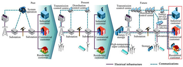
Figure 1. Smarter electricity systems.
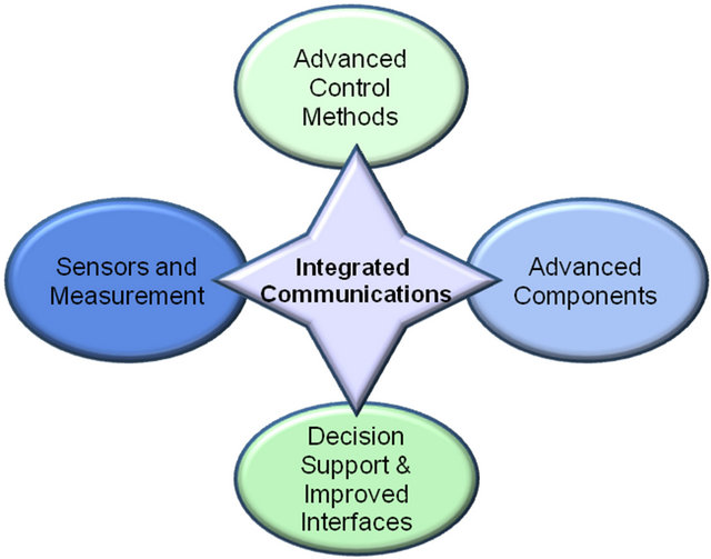
Figure 2. Advanced communication and control in smart grids.
various ESSs can be controlled in order to guarantying proper applications. Further, in modern power distribution systems, where a significant amount of the total electricity demand is met by renewable generation, ESSs can mitigate the uncertainties of energy sources (such as solar and wind) and can store the energy during high renewable production and/or low price periods, and deliver when either necessary or convenient [28-31]. Based on the ESSs technologies, in [27] the applications of ESSs are classified in instantaneous, short-, midand long-term. Instantaneous and short-term applications are involved in real time regulations, for example aiming at ancillary services provision or integration of electric drive vehicles batteries in the networks [32,33].
Energy storage systems improve the efficiency and reliability of the electric supply system by reducing the requirements for spinning reserves to meet peak power demands [34]. Storage devices can also provide frequency regulation to maintain the balance between the network’s load and power generated, and they can achieve a more reliable power supply for high tech industrial facilities as shown in Figure 3.
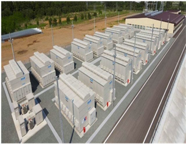
Figure 3. Distributed energy storage in a Windfarm.
High voltage power electronics, such as switches, rectifiers, inverters, and controllers, allow electric power to be precisely and rapidly controlled to support long distance transmission [35,36]. Thus, energy storage and power electronics hold substantial promise for transforming the electric power industry [28]. This capability will allow the system to respond effectively to disturbances and operate more efficiently, thereby reducing the need for additional infrastructure.
4. Available Energy Storage Systems
The adoption of smart power grid devices throughout utility networks will effect tremendous change in grid operations and usage of electricity over the next two decades. Increased deployment of energy storage devices in the distribution grid will help make this process happen more effectively and improve system performance. The energy storage systems (ESSs) applicable in power networks can be divided into two major categories [29] as shown in Figure 4. The first category being largescale storage systems that can be used in utility transmission applications. The second group includes small-scale storage systems sited at the consumer’s premises. Some of the available energy storage systems are potentially discussed in the following sub-sections.
4.1. Battery
Battery is one or more electrochemical cells that convert chemical energy into electrical energy. Batteries have been using for energy storage purpose for over one-hundred years and possess some very important, unique, and desirable features. Battery energy storage systems (BESSs) are modular, quiet, and non-polluting [37]. Batteries are manufactured in a wide variety of capacities ranging from less than 100 watts to modular configurations of several megawatts. As a result, batteries can be used for various utility applications in the areas of generation, transmission and distribution, and customer service and they can be installed relatively quickly. Battery has convenient size and voltage characteristics. The operating principle of a typical battery is shown in Figure 5.
A grid-scale BESS consists of a battery bank, control system, power electronics interfacing circuit for ac-dc power conversion, protective circuitry, and a transformer to convert the BESS output to the desired transmission or distribution system voltage level [38]. The battery bank consists of numerous batteries connected in a combination series-parallel configuration to provide the desired energy and power capabilities for the application.
The use of Lead Acid batteries for energy storage dates back to mid-1800s. There have been developed several new battery technologies to store more energy,
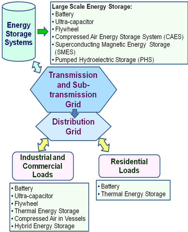
Figure 4. Energy storage systems in smart power networks.
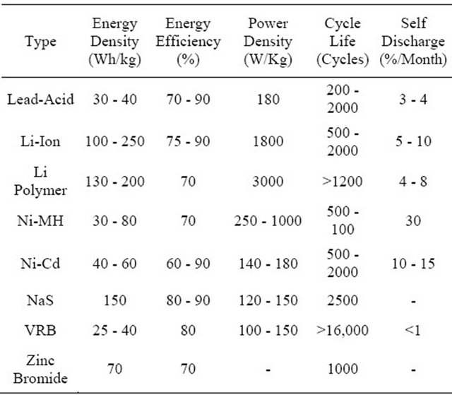
last longer and less cost than the Lead Acid battery. Battery technologies differ widely in terms of their energy and power densities, energy efficiencies, cycle-life, availability, and operating conditions. Some of these new battery technologies are Lithium Ion, Lithium Polymer, Nickel Metal Hydride (Ni-MH), Vanadium Redox (VRB), Nickel Cadmium (Ni-Cd), Sodium Sulfur (NaS), and Zinc Bromide [39-41]. Table 1 summarizes the characteristic parameters of different batteries [27,28, 42- 44].
4.2. Ultra-Capacitors
Ultra-capacitors (UCs), also known as super-capacitors, or electric double-layer capacitors (EDLCs), store energy in the electrical double layer at an electrode/electrolyte interface. There are no chemical reactions involved in the UC’s energy storage mechanism. The main parts of an electrochemical capacitor are electrodes and electrolyte. The electrical energy E accumulated in ultracapacitors is related to the capacitance C or the stored charges Q and voltage V by following formula:
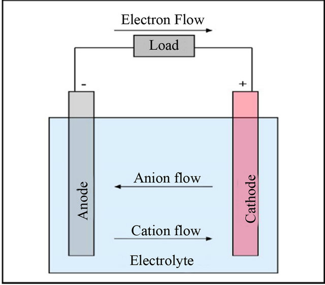
Figure 5. Working principle of a battery.
Table 1. Comparison of different types of batteries.
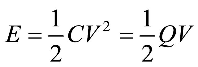 (1)
(1)
And,
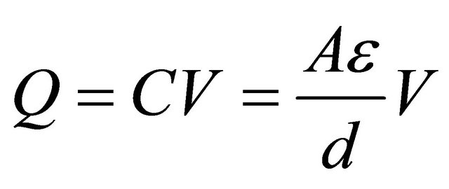 (2)
(2)
As for the conventional capacitor, the capacitance  is proportional to the area
  of the plates and the permitivity of the dielectric ε and is inversely proportional to the distance
  between the plates. UCs are designed to have a very high electrode surface area and use high permitivity dielectric. Due to the high permeability and close proximity of the electrodes, UCs have a low voltage withstand capability (usually 2 - 3 V) [30]. The electrode surface area is maximized by using porous carbon as the current collector, allowing a relatively large amount of energy to be stored at the collector surface. Therefore, UCs attain very high capacitance ratings. Larger UCs have capacities up to 5000 farads [45].
Ultracapacitors store energy by physically separating unlike charges. UCs have a long cycle life due to the fact that there are no chemical changes on the electrodes ideally in normal operation and UCs have superior efficiency. UCs also provide exceptional power density, since the charges are physically stored on the electrodes. Conversely, energy density is low since the electrons are not bound by chemical reactions [30]. The UC is temperature resistant with an operating range between −40˚C to +65˚C and is also shock and vibration resistant [46, 47].
In order to be a viable alternative in a large scale energy storage system they will need to be able to handle multiple kV. The ability of modular, non-polluting, quiet, quick charge and discharge capability, long life (10 to 12 years), and very high cycle life makes the UC a very desirable energy storage device. They can be use for short term ride through capabilities as well as voltage regulation, frequency control and other power quality issues [47,48]. UCs are currently available in many sizes. Two 3000 F capacitors are shown in Figure 6. There is even a startup company that claims to be able to create ultra capacitors with higher energy densities than lead-acid, Nickel metal hydride and even lithium ion batteries [49]. There have also been advances in the design of the ultracapacitors using nano-tube technology to improve the surface area of the capacitor. This “nano-tube ultracapacitor” would improve the ultracapacitor’s energy density to be compatible with again that of a chemical battery [46,50,51].
4.3. Flywheel
During the past decade, flywheel energy storage systems (FESSs) have been rediscovered by the power industry due to their advantages in comparison with other energy storage systems. FESSs have found an important technical role on the application of enhancing the electric power quality, grid voltage and frequency support, and unbalanced load compensation. By virtue of their high dynamics, long lifetime, and good efficiency, FESSs are well suited for short-term storage systems [52-54].
FESS consists of a flywheel coupled to permanent magnets synchronous machine (PMSM) as shown in Figure 7. Flywheels store energy in the form of momentum in a rotating wheel or cylinder. A FESS stores energy through accelerating a rotor up to a high rate of speed and maintaining the energy in the system as inertial energy. Advanced composite materials are sometimes used for the rotor to lower its weight while allowing for the extremely high speeds. The flywheel releases the energy by reversing the process and using the motor as a generator. As the flywheel releases its stored energy, the
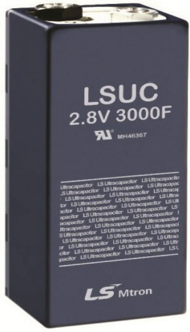
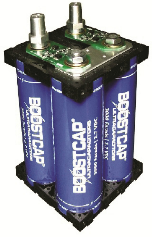
Figure 6. 3000 farad ultracapacitors.
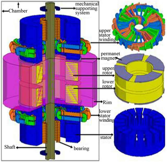
Figure 7. Flywheel energy storage system.
flywheel’s rotor slows until it is fully discharged. The energy that can be stored depends on its rotational velocity  and moment of inertia
 , as in (3). They have high power density and more energy can be stored if the flywheel rotates at higher rotational speed [55]. Power electronics are used to ensure that output voltage has appropriate amplitude and frequency characteristics.
 (3)
(3)
Flywheel energy storage systems using superconducting magnetic bearing (SMB) together with a permanent magnet bearing (PMB) is one of the most promising electro-mechanical energy storage systems consisting long life, high energy density, high efficiency, with no pollution or toxic material disposal problems, and low rotational loss by non-contact superconductor bearing [55- 57].
Flywheels have seen most commercial success targeted for power delivery capabilities typically in the 150 kW-1MW range [50,58]. Recently, a 20 MW FESS plant has been successfully established in Stephentown, New York by Beacon Power Corp. under a pilot project of the Department of Energy (DOE), New York State Energy Research and Development Authority (NYSERDA) and currently 40 MW FESS plant project is under development [59].
4.4. Superconducting Magnetic Energy Storage (SMES)
Superconducting magnetic energy storage (SMES) systems store energy in the magnetic field produced by current flowing through a superconducting coil. The SMES principle is based on inductive energy storage in the magnetic field produced by current flowing through a superconducting coil.
A SMES system consists of four major subsystems [60], plus miscellaneous equipment for system control, data collection, and so on. The major subsystems are: 1) superconducting coil with magnet (SCM); 2) power conditioning system (PCS) that controls the flow of current into and out of the coil to charge and discharge the SMES; 3) cryogenic system (CS) that maintains the coil at a low enough temperature to maintain superconductivity; and 4) the control unit (CU), as shown in Figure 8.
For a SMES system, the inductively stored energy  and the rated power
  are commonly the given specifications for SMES devices, and can be expressed as follows:
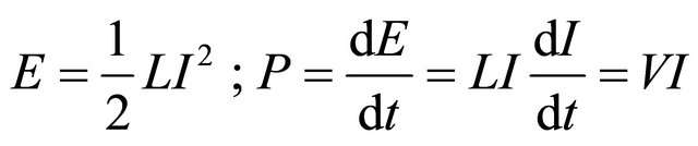 (4)
(4)
where L is the inductance of the coil, I is the dc current flowing through the coil, and V is the voltage across the coil. During SMES operation, the magnet coils have to remain in the superconducting status. A refrigerator in the cryogenic system maintains the required temperature for proper superconducting operation [61].
Among the different variants of flexible alternating current transmission system (FACTS) devices and ESSs currently available, static synchronous compensators (STATCOM) integrated with SMES has been proposed as the most adequate for participating of the primary frequency control because of SMES has high efficiency (95% to 98% [61]) and rapid response to power demand [62-64]. Depending on the control loop of its power conversion unit and switching characteristics, the SMES system can respond very rapidly (MWs/milliseconds). The ability of injecting/absorbing real or reactive power can increase the effectiveness of the control, and enhance system reliability and availability. Comparing with other storage technologies, the SMES technology has a unique advantage in two types of applications: Power system transmission control and stabilization, and power quality improvement [65].
Several SMESs in the range of kWh to MWh scale have been already implemented for compensation of load/ generation fluctuation as well as energy storage [66]. Recently, 10 MVA/20 MJ SMES prototype has been tested at an actual power system including hydro power generators in order to compensate the fluctuating power load for a metal rolling factory [67].
4.5. Compressed Air Energy Storage System (CAES)
Compressed air energy storage system (CAES) is a hybrid technology of long term power storage and generation. A CAES plant mainly consists of 1) compressor train; 2) motor-generator unit; 3) gas turbine; and 4) underground compressed air storage tank (see Figure 9). During low-cost off-peak load periods, air is compressed and stored in large underground salt caverns [68]. Upon demand, the process is reversed; the compressed air is returned to the surface; this air is used to burn natural gas in the combustion chambers. The resulting combustion gas is then expanded in the two-stage gas turbine to spin
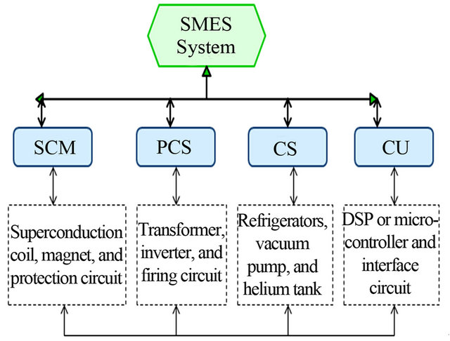
Figure 8. Block diagram of an SMES system.
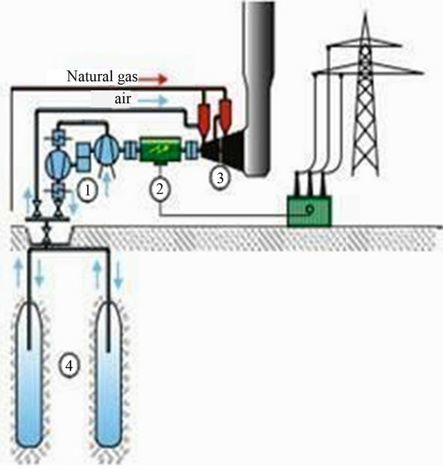
Figure 9. Major components of a CAES plant.
the generator and produce electricity.
CAES can be placed near consumers and in large, small, and micro scale smart power networks. As in many countries, the potentials of installing new hydrostorage plants with pumping facilities are limited and many other energy storage devices are far from being economic, CAES may be an attractive investment opportunity for such purposes. The first such plant was built in Huntorf, Germany, in 1978 with a capacity of 290 MW [68]. In 1991, the first U.S. CAES facility was built in McIntosh, Alabama, by the Alabama Electric Cooperative and EPRI, and has a capacity rating of 110 MW [69]. Liu et al. [70] has proposed a novel hybridfuel CAES system for China. The design is based on using standard, industry proven equipment components to deliver a reliable and economic compressed air energy cycle. The resulting CAES plant consists of 410 MW generation, 205 MW of compression, and 2050 MW of storage.
In the past few years, research has been conducted to improve the efficiency of the turbines and heat transfer mechanisms used to pump and retrieve compressed air [71-73]. In an adiabatic CAES, the air’s heat energy is stored separately and recovered before the compressed air is expanded in an air turbine. Such plants are currently under development and promise higher efficiencies and zero direct CO2-emissions [71].
4.6. Pumped Hydroelectric Storage
Pumped hydroelectric storage (PHS) is the oldest kind of large-scale energy storage technology [74]. Since 1904, they are in active operation and new ones are still being built because of their operational flexibility and ability to provide rapid response to changes in system loading or spot price of electricity.
Conventional pumped hydroelectric storage consists of two large reservoirs, one is located at base level and the other is situated at a different elevation. Water is pumped to the upper reservoir where it can be stored as potential energy. Upon demand, water is released back into the lower reservoir, passing through hydraulic turbines which generate electrical power as high as 1000 MW. Pumped hydroelectric storage has huge energy and power capacity. Recently [75-77] examined the impact of pumped storage units together with large renewable penetration. They focused on reducing system operating costs and maximizing usage of renewable energy based on unit commitments and dispatches. Currently, efforts aimed at increasing the use of pumped hydro storage are focused on the development of underground facilities. Modern pumped storage plants are often designed to have fast start, load ramping and unloading capabilities. They can respond to load changes within seconds.
4.7. Hybrid Energy Storage System
The selection of the energy storage system for a particular application in power grid sometimes depends on a suitable combination of the power and energy ratings, energy, power density, cost, weight, volume, and operating temperature etc of ESSs. These requirements may not be achievable from a single energy storage source. To implement such optimal applications, hybrid energy storage devices (HESDs) have been proposed. In a HESD, two or more different energy storage systems with complementary characteristics can be combined together electronically. For future grid application proposed HESDs are listed next, with the energy-supplying device listed first, followed by the power-supplying device:
1) battery and ultracapacitor [78-81];
2) battery and flywheels [82];
3) CAES and battery or ultracapacitor [83];
4) battery and SMES [84].
Figure 10 demonstrates the relationship between power operational range and discharge time at rated power for various energy storage systems such as battery, ultracapacitors, flywheel, SMES, CAES, and pumped hydro. Table 2 summarizes the characteristic parameters of different energy storage technologies [30,42-44,59,83].
5. Concluding Remarks
In this paper the potential application of different ESSs and their prospect have been discussed and analyzed in detail for future smart power grids. Energy can be stored both for short and long durations. Various storage systems are available for these purposes. The importance of storage systems in electricity grids is finally receiving the attention of system planners as more storage options participation of storage is increasing. The design of smart
Table 2. Comparison of various energy storage systems.
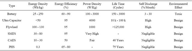
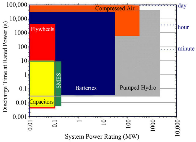
Figure 10. The relationship between power rating and discharge time for different storage technologies.
grids in the future will take advantage of storage to deal with more dynamic loads and sources. As market rules are adjusted to take advantage of the benefits of bulk and distributed storage devices, the overall capabilities and reliability of more complex electricity networks should continue to improve as fully integrated smart grids.
REFERENCES
- K. Moslehi and R. Kumar, “A Reliability Perspective of the Smart Grid,” IEEE Transactions on Smart Grid, Vol. 1, No. 1, 2010, pp. 57-64. doi:10.1109/TSG.2010.2046346
- P. Zhang, F. Li and N. Bhatt, “Next-Generation Monitoring, Analysis, and Control for the Future Smart Control Center,” IEEE Transactions on Smart Grid, Vol. 1, No. 2, 2010, pp. 186-192. doi:10.1109/TSG.2010.2053855
- S. M. Amin and B. F. Wollenberg, “Toward a Smart Grid: Power Delivery for the 21st Century,” IEEE Power Energy Magazine, Vol. 3, No. 5, 2005, pp. 34-41. doi:10.1109/MPAE.2005.1507024
- International Energy Agency, “Technology Roadmap: Smart Grids,” 2011. http://www.iea.org/publications/freepublications/publication/name,3972,en.html
- US Department of Energy, “How the Smart Grid Promotes a Greener Future,” 2010. http://energy.gov/oe/downloads/how-smart-grid-promotes-greener-future
- H. Gharavi and R. Ghafurian, “Smart Grid: The Electric Energy System of the Future,” IEEE Proceedings, Vol. 99, No. 6, 2011, pp. 917-921.
- J. Xia and Y. Wang, “Secure Key Distribution for the Smart Grid,” IEEE Transactions on Smart Grid, Vol. 3, No. 3, 2012, pp. 1437-1443.
- A. Molderink, V. Bakker, M. G. C. Bosman, J. L. Hurink and G. J. M. Smit, “Management and Control of Domestic Smart Grid Technology,” IEEE Transactions on Smart Grid, Vol. 1, No. 2, 2010, pp. 109-119. doi:10.1109/TSG.2010.2055904
- A. Bose, “Smart Transmission Grid Applications and Their Supporting Infrastructure,” IEEE Transactions on Smart Grid, Vol. 1, No. 1, 2010, pp. 11-19. doi:10.1109/TSG.2010.2044899
- B. P. Roberts and C. Sandberg, “The Role of Energy Storage in Development of Smart Grids,” IEEE Proceedings, Vol. 99, No. 6, 2011, pp. 1139-1144. doi:10.1109/JPROC.2011.2116752
- M. S. Whittingham, “History, Evolution, and Future Status of Energy Storage,” IEEE Proceedings, Vol. 100, No. , 2012, pp. 1518-1534.
- G. D. Rodriguez, “A Utility Perspective of the Role of Energy Storage in the Smart Grid,” 2010 IEEE Power and Energy Society General Meeting, Minneapolis, 25-29 July 2010, pp. 1-2. doi:10.1109/PES.2010.5589870
- US Department of Energy, “Energy Storage—A Key Enabler of the Smart Grid,” 2009. http://www.netl.doe.gov/smartgrid/refshelf.html#White%20Papers
- US Department of Energy, “The Smart Grid: An Introduction, 2008. http://energy.gov/oe/downloads/smart-grid-introduction-0
- F. Li, W. Qiao, H. Sun, H. Wan, J. Wang, et al., “Smart Transmission Grid: Vision and Framework,” IEEE Transactions on Smart Grid, Vol. 1, No. 2, 2010, pp. 168-177. doi:10.1109/TSG.2010.2053726
- M. D. Hopkins, A. Pahwa and T. Easton, “Intelligent Dispatch for Distributed Renewable Resources,” IEEE Transactions on Smart Grid, Vol. 3, No. 2, 2012, pp. 1047- 1054. doi:10.1109/TSG.2012.2190946
- S. S. S. R. Depuru, L. Wang, V. Devabhaktuni and N. Gudi, “Smart Meters for Power Grid—Challenges, Issues, Advantages and Status,” 2011 IEEE/PES Power Systems Conference and Exposition (PSCE), Phoenix, 20-23 March 2011, pp. 1-7. doi:10.1109/PSCE.2011.5772451
- D. Rua, D. Issicaba, F. J. Soares, P. M. R. Almeida, R. J. Rei and J. A. P. Lopes, “Advanced Metering Infrastructure Functionalities for Electric Mobility,” 2010 IEEE PES Innovative Smart Grid Technologies Conference Europe (ISGT Europe), Porto, 11-13 October 2010, pp. 1-7.
- H. Suleiman, K. A. Ahmed, N. Zafar, et al., “Inter-Domain Analysis of Smart Grid Domain Dependencies Using Domain-Link Matrices,” IEEE Transactions on Smart Grid, Vol. 3, No. 2, 2012, pp. 692-709. doi:10.1109/TSG.2011.2176151
- Microsoft Power and Utilities, “Smart Energy Reference Architecture (SERA),” 2009.
- A. P. S. Meliopoulos, G. Cokkinides, R. Huang, E. Farantatos, S. Choi, et al., “Smart Grid Technologies for Autonomous Operation and Control,” IEEE Transactions on Smart Grid, Vol. 2, No. 1, 2011, pp. 1-10. doi:10.1109/TSG.2010.2091656
- A. Ipakchi and F. Albuyeh, “Grid of the Future,” IEEE Power Energy Magazine, Vol. 7, No. 2, 2009, pp. 52-62. doi:10.1109/MPE.2008.931384
- R. A. F. Currie, G. W. Ault, C. E. T. Foote, N. M. McNeill, et al., “Smarter Ways to Provide Grid Connections for Renewable Generators,” IEEE PES General Meeting, Minneapolis, 25-29 July 2010, pp. 1-6.
- Q. Pang, H. Gao and M. Xiang, “Design of Intelligent Terminal Unit for Smart Distribution Grid,” Proceedings of the IEEE China International Conference on Electricity Distribution (CICED), Nanjing, 13-16 September 2010, pp. 1-6.
- F. Rahimi and A. Ipakchi, “Demand Response as a Market Resource under the Smart Grid Paradigm,” IEEE Transactions on Smart Grid, Vol. 1, No. 1, 2010, pp. 82-88. doi:10.1109/TSG.2010.2045906
- E. Santacana, G. Rackliffe, L. Tang and X. Feng, “Getting Smart,” IEEE Power Energy Magazine, Vol. 8, No. 2, 2010, pp. 41-48. doi:10.1109/MPE.2009.935557
- K. C. Divya and J. Østergaard, “Battery Energy Storage Technology for Power Systems: An Overview,” Electric Power System Research, Vol. 79, No. 4, 2009, pp. 511- 520. doi:10.1016/j.epsr.2008.09.017
- M. M. Chowdhury, M. E. Haque, M. Aktarujjaman, M. Negnevitsky and A. Gargoom, “Grid Integration Impacts and Energy Storage Systems for Wind Energy Applications—A Review,” Proceedings of the IEEE PES General Meeting, San Diego, 24-29 July 2011, pp. 1-8.
- S. C. Smith, P. K. Sen and B. Kroposki, “Advancement of Energy Storage Devices and Applications in Electrical Power System,” IEEE PES General Meeting, Pittsburgh, 20-24 July 2008, pp. 1-8.
- S. Vazquez, S. M. Lukic, E. Galvan, L. G. Franquelo, et al., “Energy Storage Systems for Transport and Grid Applications,” IEEE Transactions on Industrial Electronics, Vol. 57, No. 12, 2010, pp. 3881-3895. doi:10.1109/TIE.2010.2076414
- A. A. Thatte and L. Xie, “Towards a Unified Operational Value Index of Energy Storage in Smart Grid Environment,” IEEE Transactions on Smart Grid, Vol. 3, No. 3, 2012, pp. 1418-1426.
- W. Kempton and J. Tomic, “Vehicle-to-Grid Power Fundamentals: Calculating Capacity and Net Revenue,” Journal of Power Sources, Vol. 144, No. 1, 2005, pp. 268-279. doi:10.1016/j.jpowsour.2004.12.025
- A. Bracale, P. Caramia and D. Proto, “Optimal Operation of Smart Grids Including Distributed Generation Units and Plug in Vehicles,” International Conference on Renewable Energies Power Quality (ICREPQ’11), Las Palmas de Gran Canaria, 13-15 April 2011, pp. 553-558.
- M. M. Biswas, K. K. Das, I. A. Baqee, M. A. H. Sadi and H. M. S. Forhad, “Prospects of Renewable Energy and Energy Storage Systems in Bangladesh and Developing Economics,” Global Journal of Researches in Engineering (GJRE), Vol. 11, No. 5, 2011, pp. 23-31.
- Y. M. Cheng, Y. C. Liu, S. C. Hung and C. S. Cheng, “Multi-Input Inverter for Grid-Connected Hybrid PV/ Wind Power System,” IEEE Transactions on Power Electronics, Vol. 22, No. 3, 2007, pp. 1070-1076. doi:10.1109/TPEL.2007.897117
- J. M. Carrasco, L. G. Franquelo, J. T. Bialasiewicz, E. Galvan, R. C. P. Guisado, et al., “Power Electronic Systems for the Grid Integration of Renewable Energy Sources: A Survey,” IEEE Transactions on Power Electronics, Vol. 53, No 4, 2006, pp. 1002-1016. doi:10.1109/TIE.2006.878356
- R. B. Schainker, “Executive Overview: Energy Storage Options for a Sustainable Energy Future,” IEEE PES General Meeting, Palo Alto, June 2004, Vol. 2, pp. 2309- 2314.
- C. A. Hill, M. C. Such, D. Chen, J. Gonzalez, et al., “Battery Energy Storage for Enabling Integration of Distributed Solar Power Generation,” IEEE Transactions on Smart Grid, Vol. 3, No. 2, 2012, pp. 850-857. doi:10.1109/TSG.2012.2190113
- J. McDowall, “Nickel-Cadmium Batteries for Energy Storage Applications,” The 14th Annual Battery Conference on Applications and Advances, Long Beach, 12-15 January 1999, pp. 303-308.
- J. P. Barton and D. G. Infield, “Energy Storage and Its Use with Intermittent Renewable Energy,” IEEE Transactions on Energy Conversion, Vol. 19, No. 2, 2004, pp. 441-448. doi:10.1109/TEC.2003.822305
- P. C. Symons, “Opportunities for Energy Storage in Stressed Electrical Supply Systems,” IEEE PES Summer Meeting, Vancouver, July 2001, Vol. 1, pp. 448-449.
- D. Y. Goswami and F. Kreith, “Energy Conversion,” CRC Press, Boca Raton, 2007. doi:10.1201/9781420044324
- A. A. H. Hussein, S. Harb, N. Kutkut, J. Shen and I. Batarseh, “Design Considerations for Distributed MicroSto- rage Systems in Residential Applications,” 32nd International Telecommunications Energy Conference (INTELEC), Orlando, 6-10 June 2010, pp. 1-6.
- B. R. Williams and T. Hennessy, “Energy Oasis [Vanadium Redox Battery System in Power Distribution Application],” IEEE Power Engineer, Vol. 19, No. 1, 2005, pp. 28-31. doi:10.1049/pe:20050105
- Nesscap Ultracapacitors Products, “(EDLC) Electric Double-Layer Capacitor,” 2012. http://www.nesscap.com/product/edlc_large1.jsp
- D. Halber, “Researchers Fired Up over New Battery,” MIT Tech Talk, Vol. 50, No. 16, 2006, pp. 1-5. http://web.mit.edu/newsoffice/2006/batteries-0208.html
- Maxwell Technologies, “An Overview of Ultracapacitor Technology,” 2012. http://www.maxwell.com/ultracapacitors/
- R. D. Weir and C. W. Nelson, “Utilization of Poly (Ethylene Terephthalate) Plastic and Composition-Modified Barium Titanate Powders in a Matrix that Allows Polarization and the Use of Integrated-Circuit Technologies for the Production of Lightweight Ultrahigh Electrical Energy Storage Units (EESU),” US Patent No. 7466536, 2008.
- H. Pan, J. Li and Y. P. Feng, “Carbon Nanotubes for Supercapacitor,” Nanoscale Research Letters, Vol. 5, No. 3, 2010, pp. 654-668. doi:10.1007/s11671-009-9508-2
- H. Zhang, G. P. Cao, Y. S. Yang and Z. N. Gu, “Comparison between Electrochemical Properties of Aligned Carbon Nanotube Array and Entangled Carbon Nanotube Electrodes,” Journal of Electrochemical Society, Vol. 155, No. 2, 2008, pp. 19-22. doi:10.1149/1.2811864
- R. Hebner, J. Beno and A. Walls, “Flywheel Batteries Come Around Again,” IEEE Spectrum, Vol. 39, No. 4, 2002, pp. 46-51. doi:10.1109/6.9 93788
- G. Cimuca, C. Saudemont, B. Robyns and M. M. Radulescu, “Control and Performance Evaluation of a Flywheel Energy Storage System Associated to a VariableSpeed Wind Generator,” IEEE Transactions on Industrial Electronics, Vol. 53, No. 4, 2006, pp. 1074-1085. doi:10.1109/TIE.2006.878326
- G. Cimuca, S. Breban, M. Radulescu, C. Saudemont, et al., “Design and Control Strategies of an Induction-Machine-Based Flywheel Energy Storage System Associated to a Variable-Speed Wind Generator,” IEEE Transactions on Energy Conversion, Vol. 25, No. 2, 2010, pp. 526-534. doi:10.1109/TEC.2010.2045925
- M. Subkhan and M. Komori, “New Concept for Flywheel Energy Storage System Using SMB and PMB,” IEEE Transactions on Applied Superconductivity, Vol. 21, No. 3, 2011, pp. 1485-1488. doi:10.1109/TASC.2010.2098470
- J. Lee, S. Jeong, Y. H. Han and B. J. Park, “Concept of Cold Energy Storage for Superconducting Flywheel Energy Storage System,” IEEE Transactions on Applied Superconductivity, Vol. 21, No. 3, 2011, pp. 2221-2224. doi:10.1109/TASC.2010.2094177
- T. Ichihara, K. Matsunaga, M. Kita, I. Hirabayashi, et al., “Application of Superconducting Magnetic Bearings to a 10 kWh-Class Flywheel Energy Storage System,” IEEE Transactions on Applied Superconductivity, Vol. 15, No. 2, 2005, pp. 2245-2248. doi:10.1109/TASC.2005.849622
- N. Hamsic, A. Schmelter, A. Mohd, et al., “Stabilising the Grid Voltage and Frequency in Isolated Power Systems Using a Flywheel Energy Storage System,” The Great Wall World Renewable Energy Forum, Beijing, 23-27 October 2006, pp. 1-6.
- E. Ortjohann, N. Hamsic, A. Schmelter, et al., “Increasing Renewable Energy Penetration in Isolated Grids Using a Flywheel Energy Storage System,” International Conference on Power Engineering, Energy and Electrical Drives, Setubal, 12-14 April 2007, pp. 195-200.
- M. Lazarewicz and J. Judson, “Performance of First 20 MW Commercial Flywheel Frequency Regulation Plant,” ESA 2011 Annual Meeting, Beacon Power Corporation, San Jose, June 2011.
- [61] D. Sutanto and K. W. E. Cheng, “Superconducting Magnetic Energy Storage Systems for Power System Applications,” International Conference on Applied Superconductivity and Electromagnetic Devices, Chengdu, 25-27 September 2009, pp. 377-380.
- [62] IEEE Task Force and T&D Committee, “Detailed Modeling of Superconducting Magnetic Energy Storage (SMES) System,” IEEE Transactions on Power Delivery, Vol. 21, No. 2, 2006, pp. 699-710. doi:10.1109/TPWRD.2005.864075
- [63] V. Karasik, K. Dixon, C. Weber, B. Batchelder, G. Campbell and P. Ribeiro, “SMES for Power Utility Applications: A Review of Technical and Cost Considerations,” IEEE Transactions on Applied Superconductivity, Vol. 9, No. 2, 1999, pp. 541-546. doi:10.1109/77.783354
- [64] M. G. Molina and P. E. Mercado, “Comparative Evaluation of Performance of a STATCOM and SSSC both Integrated with SMES for Controlling the Power System Frequency,” 2004 IEEE/PES Transmission and Distribution Conference and Exposition: Latin America, São Paulo, 8-11 November 2004, pp. 535-541.
- [65] M. G. Molina and P. E. Mercado, “New Energy Storage Devices for Applications on Frequency Control of the Power System Using FACTS Controllers,” Proceedings of X ERLAC, Iguazú, 18-22 May 2003, pp. 1-6.
- [66] Y. Tatusuta, S. Koso, H. Abe, M. Urata, H. Ohsaki, et al., “Development of SMES for Power System Control,” IEEE Transactions on Applied Superconductivity, Vol. 14, No. 2, 2004, pp. 693-698. doi:10.1109/TASC.2004.830033
- [67] S. Nomura, T. Shintomi, S. Akita, T. Nitta, R. Shimada and S. Meguro, “Technical and Cost Evaluation on SMES for Electric Power Compensation,” IEEE Transactions on Applied Superconductivity, Vol. 20, No. 3, 2010, pp. 1373- 1378. doi:10.1109/TASC.2009.2039745
- [68] Q. Li, “Status and Future Prospect of SMES for Grid Applications,” Advanced Microgrid Concepts and Technologies Workshops, Brookhaven National Laboratory, Washington DC, 2012.
- [69] F. Crotogino, K. U. Mohmeyer and R. Scharf, “Huntorf CAES: More than 20 Years of Successful Operation,” The Solution Mining Research Institute Spring Meeting, Orlando, 23-25 April 2001.
- [70] Electric Power Research Institute, “Compressed Air Energy Storage: 1994,” EPRI Brochure BR-102936.
- [71] W. Liu, Y. Yang, W. Zhang, G. Xu and Y. Wu, “A Novel Hybrid-Fuel Compressed Air Energy Storage System for China’s Situation,” Proceedings of the International Conference of Efficiency, Cost, Optimization, Simulation Environmental Impact Energy Systems, Perugia, 26-29 June 2012, pp. 1-16.
- [72] C. Bullough, C. Gatzen, C. Jakiel, M. Koller, et al., “Advanced Adiabatic Compressed Air Energy Storage for the Integration of Wind Energy,” Proceedings of European Wind Energy Conference, EWEC, London, 22-25 November 2004, pp. 1-8.
- [73] C. Linnemann and M. W. Coney, “The Isoengine: Realization of a High-Efficiency Power Cycle Based on Isothermal Compression,” International Journal of Energy Technology and Policy, Vol. 3, No. 1-2, 2005, pp. 66-84. doi:10.1504/IJETP.2005.006740
- [74] Ridge Energy Storage & Grid Services L. P., “The Economic Impact of CAES on Wind in TX, OK and NM,” Texas State Energy Conservation Office, Austin, 2005.
- [75] P. Breeze, “Power Generation Technologies,” Elsevier, Boston, 2005.
- [76] P. Brown, J. Lopes and M. Matos, “Optimization of Pumped Storage Capacity in an Isolated Power System with Large Renewable Penetration,” IEEE Transactions on Power Systems, Vol. 23, No. 2, 2008, pp. 523-531. doi:10.1109/TPWRS.2008.919419
- [77] J. G. Gonzalez, R. D. L. Muela, L. Santos and A. Gonzalez, “Stochastic Joint Optimization of Wind Generation and Pumped-Storage Units in an Electricity Market,” IEEE Transactions on Power Systems, Vol. 23, No. 2, 2008, pp. 460-468. doi:10.1109/TPWRS.2008.919430
- [78] A. Tuohy and M. O’Malley, “Impact of Pumped Storage on Power Systems with Increasing Wind Penetration,” IEEE Power & Energy Society General Meeting, Calgary, 26-30 July 2009, pp. 1-8.
- [79] W. Henson, “Optimal Battery/Ultracapacitor Storage Combination,” Journal of Power Sources, Vol. 179, No. 1, 2008, pp. 417-423. doi:10.1016/j.jpowsour.2007.12.083
- [80] H. Yoo, S. K. Sul, Y. Park and J. Jeong, “System Integration and Power Flow Management for a Series Hybrid Electric Vehicle Using Super-Capacitors and Batteries,” IEEE Transactions on Applied Superconductivity, Vol. 44, No. 1, 2008, pp. 108-114. doi:10.1109/TIA.2007.912749
- [81] L. Shuai, K. A. Corzine and M. Ferdowsi, “A New Battery/Ultracapacitor Energy Storage System Design and Its Motor Drive Integration for Hybrid Electric Vehicles,” IEEE Transactions on Vehicular Technology, Vol. 56, No. 4, 2007, pp. 1516-1523. doi:10.1109/TVT.2007.896971
- [82] M. B. Camara, H. Gualous, F. Gustin and A. Berthon, “Design and New Control of DC/DC Converters to Share Energy between Supercapacitors and Batteries in Hybrid Vehicles,” IEEE Transactions on Vehicular Technology, Vol. 57, No. 5, 2008, pp. 2721-2735. doi:10.1109/TVT.2008.915491
- [83] O. Briat, J. M. Vinassa, W. Lajnef, S. Azzopardi and E. Woirgard, “Principle, Design and Experimental Validation of a Flywheel-Battery Hybrid Source for Heavy-Duty Electric Vehicles,” IET Electric Power Applications, Vol. 1, No. 5, 2007, pp. 665-674. doi:10.1049/iet-epa:20060458
- [84] S. Lemofouet and A. Rufer, “A Hybrid Energy Storage System Based on Compressed Air and Supercapacitors with Maximum Efficiency Point Tracking (MEPT),” IEEE Transactions on Industrial Electronics, Vol. 53, No. 4, 2006, pp. 1105-1115. doi:10.1109/TIE.2006.878323
- [85] T. Ise, M. Kita and A. Taguchi, “A Hybrid Energy Storage with a SMES and Secondary Battery,” IEEE Transactions on Applied Superconductivity, Vol. 15, No. 2, 2005, pp. 1915-1918. doi:10.1109/TASC.2005.849333
NOTES
*Corresponding author.