Energy and Power Engineering
Vol. 4 No. 6 (2012) , Article ID: 25088 , 6 pages DOI:10.4236/epe.2012.46065
A Novel Coordinated Sliding Mode Controller Based on Lyapunov Method for SVC, Excitation and Steam Valving
1Suining Breach of Sichuan Power Electric Corporation, Suining, China
2School of Automation Engineering, University of Electronic Science and Technology of China, Chengdu, China
3School of Electrical Engineering, Southwest Jiaotong University, Chengdu, China
Email: hunter_djw@163.com
Received June 10, 2012; revised July 15, 2012; accepted July 28, 2012
Keywords: SVC; Excitation and Steam Alving; Sliding Mode Control; Lyapunov; Simulation
ABSTRACT
A novel coordinated controller is proposed in the paper for SVC, excitation and steam valving for a single machine infinite system. Firstly, the nonlinear mathematic model of the system including the itation and steam valving is exactly linearized via state feedback. Then, the quasi-linearized system after the exact lineariztion is controlled by the sliding model controller based on Lyapunov direct method. At last, the novel coordinated controller is compared with a traditional linear controller and a nonlinear optimal controller respectively by simulations. The simulation results show that the proposed controller gives better dynamic response and stronger robustness.
1. Introduction
[1,2] presented a novel nonlinear optimal excitation controller and a nonlinear variable structure excitation controller. [3] applied nonlinear robustness excitation controller with voltage regulation. [1,4-6] adopted SVC controller to restrain the system sub-synchronous oscillation, and damp the voltage fluctuation. [7-9] designed a cooperated controller for a SVC and excitation controller to improve system stability. The excitation controller and steam valving controller are proposed to increase the performance of the system in [10].
In this paper, a novel coordinated sliding mode control based on Lyapunov method is used to generate the control schemes for the SVC, Excitation and Steam Valving. In order to achieve superior performance for the power system, the coordination between the SVC, Excitation and Steam Valving is studied to avoid poor interaction.
2. Mathematical Model
A single generator—infinite bus power system with SVC is shown in Figure 1.
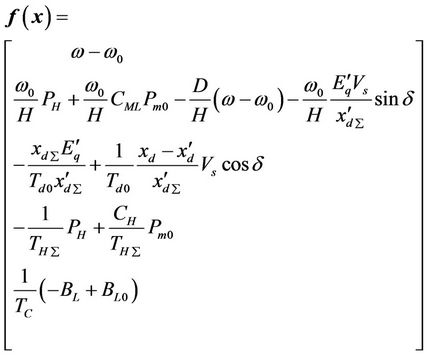
For a generator set connected to a single generator infinite bus power system with SVC, traditional transient behavior equations can be described as follows [1,6]:
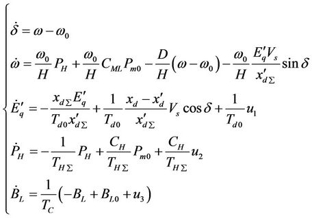 (1)
(1)
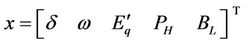
where, Td0 is the direct axis transient short circuit time constant, Pm0 the initial mechanical power, PH the mechanical power generated by the HP turbine in per unit, H the inertia coefficient, D the damping constant,  the transient EMF in the quadrature axis of the generator. CH and CML are the power distribution coefficients of the HP and the MP/LP steam turbine subsystems. THΣ and TMΣ are the equivalent time constants of the HP and MP/LP steam value control system respectively. δ is the rotor angle in radian/s and ω the radial speed of the machine. TC is the time constant of SVC regulator.
  is the direct axis transient. xd is the direct axis reactance of the generator, BL is the susceptance of the inductor in SVC, BC is the susceptance of the capacitor in SVC, u1 is the control input of the excitation system. u1 is the control input of SVC. u1 is the control input of the HP steam turbine subsystems.
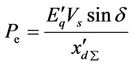
Pm is the mechanical power. Pe is the active electrical power delivered by the generator, and given by:
The equations above describe a five-order three-input three-output affine nonlinear system and can be rewritten in a normal form as follows:
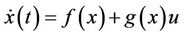 (2)
(2)
where
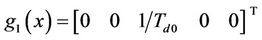 ,
,
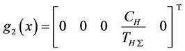 ,
,
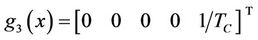 ,
,
3. Global Linearization
The output functions have a significant relationship with state variables which will be controlled. The output functions may be state variable or the system actual output variable, but system actual output variable must be the function of state variables. In this paper, we choose output functions considering the following aspects:
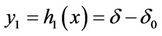
1) Consider the Stability of δ, we can choose
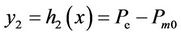
2) Consider the impact of stream valve on active electrical power, we can choose,
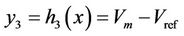
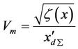
3) Consider the Stability of SVC Connection point voltage, y3 is adopted as follows:
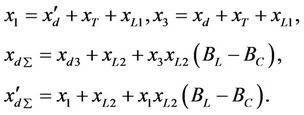
According to circuit principle,  is given by:
where
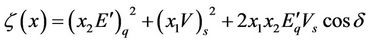 ,
,
 is the reference voltage.
First, calculate the relative degree of the system as follows:
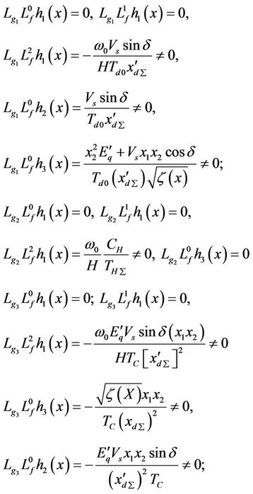
The matrix:
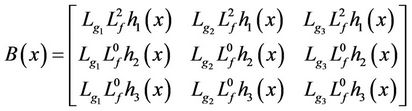
 is nonsingular in whole state space, so, the relative
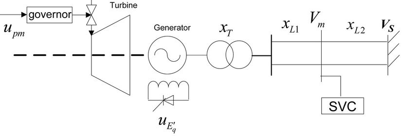
Figure 1. The single machine infinite system with SVC.
degree set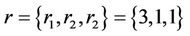 , and
, and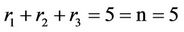 .
.
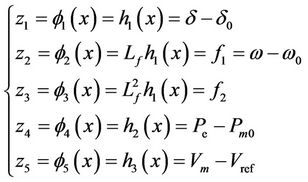
 as a new state vector,
  can be given by:
 (3)
(3)
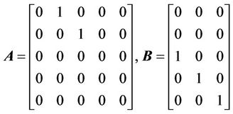
Thus, a Brunowsky canonical form is written as:
 (4)
(4)
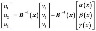
the model for the power system described in Equation (2) can be rewritten as:
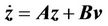 (5)
(5)
A and B are constant matrix, and V is a vector of virtual inputs.
where
Getting easily:
 (6)
(6)
where,
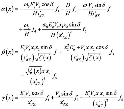
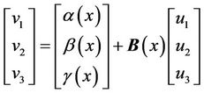
the output for the power system described in Equation (2) is represented as follows::
 (7)
(7)
4. Sliding Mode Controller Based on Lyapunov Method
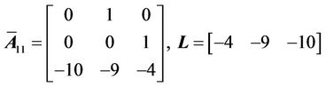
Consider the equation of the system described in Equation (5), A is decomposed into three Jordan sub-matrix as
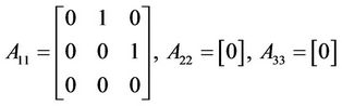
The system is decomposed into three sub-system for controllers design independently. At First, for the corresponding subsystem A11, Sliding mode control based on Lyapunov method is used to design the anticipated dynamic characteristics.
Here,  is Controllable, LTZ is introduced to obtain
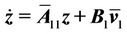 (8)
(8)
where,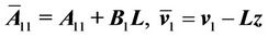 . Here,
  Eigenvalues are –2 and –1 ± 2j. According to pole allocation method for the controllable canonical form system, we can get
For the system described in Equation (8), we can choose
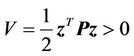 (9)
(9)
Afterward,
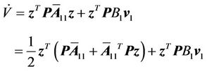 (10)
(10)
where, P is the solution of the Lyapunov equation as
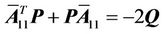 (11)
(11)
Q in (11) is a positive definite matrix.
Switching hypersurface equation is chosen as
 (12)
(12)
where
 .
.
On the sliding mode hypersurface, we can get easily  according to Equations (10) and (11), we can know
  as
as
 (13)
(13)
In Equation (13), V is positive and  is negative, so sliding mode movement is asymptotically stable. The control variable
  is out of service on the switching hypersurface.
To get better performance, the index asymptotic law control is adopted as follows:
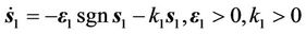 (14)
(14)
Thus,
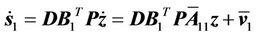 (15)
(15)
According to Equations (14) and (15), we can obtain the virtual input
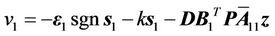 (16)
(16)
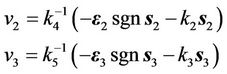
For the subsystem A22 and A33, we can design independently two controller v2 and v3 according to pole allocation of linear system. Switching hypersurface equations are taken as follows:
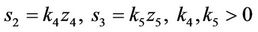
where, k4 and k5 are constants, respectively.
The index asymptotic law controls for the subsystem A22 and A33 are adopted as
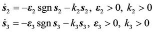
where, k2, k3, ε2 and ε3 are positive constants.
Then,
 (17)
(17)
To eliminate the chattering phenomenon on the sliding mode surface, we substitute the sign function with a saturation function as
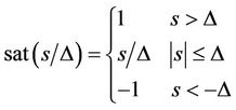
where, Δ is the boundary of the saturation function, and  is the switching control term.
Therefore, according to Equations (16) and (17), we can formulate the final control laws of the whole system as
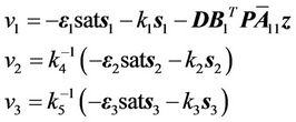 (18)
(18)
5. Simulation Results
A simulation case is given as follows: H = 8, D = 5, Vs = 1, xd = 0.779, x`d = 0.14, Td0 = 6.9, xL1 = 0.38, xL2 = 0.54, xT = 0.01, Tc = 0.2, BL0 = 0.3, Bc = 1.22, Vref = 1, CH = 0.4, TH∑ = 0.45, ε1 =ε2 = ε3 = 0.1, k1 = k2 = k3 = 5, k4 k5 = 1, Q = I, Δ = 0.2, 0 ≤ E΄q ≤ 3.3, 0 ≤ BL ≤ 1.5. The parameters of equilibrium point are chosen as Pm0 = 0.79,δ0 = 60˚,ω0 = 314.16.
Case 1: by comparing traditional linear controller (TLC) with the controller (NSVC) designed in this paper, we study the controller’s dynamic performances. It is assumed that a short circuit fault occurs at the high voltage side of the transformer at 1s and is cleared at 1.2 s. The swing curves of the dynamic system are given in Figure 2.
It can be seen from Figure 2 that the novel sliding mode controller based on Lyapunov method for coordinating SVC, excitation, and steam valving improves power angle stability, damps the system frequency oscillation and prevents active electrical power and SVC voltage from fluctuation.
Case 2: the proposed controller is compared with NOPC in references [1]. It is assumed that the short circuit fault occurs on xL2 at 1 s, and the faulting line is
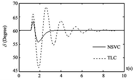
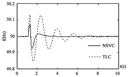
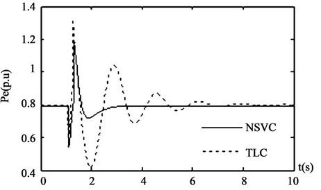

Figure 2. Responses of system under the disturbance 1.
opened at 1.2 s to supply the power with a single line. The second line returns successfully at 1.9 s. The swing curves of the dynamic system are given in Figure 3.
Figure 3 shows that the novel coordinated controller gives better dynamic response and stronger robustness.

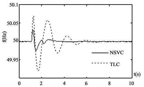
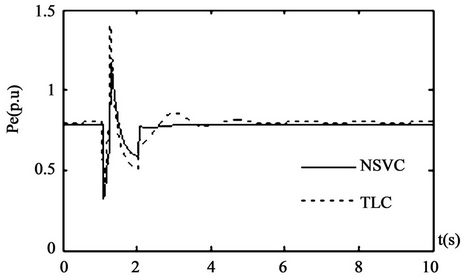
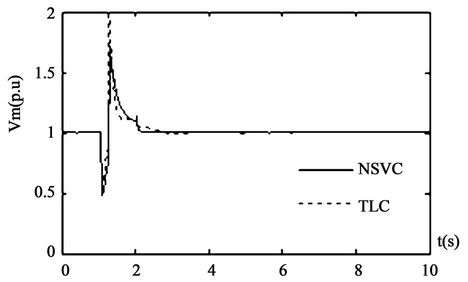
Figure 3. Responses of system under the disturbance 2.
6. Conclusions
This paper proposes a set of novel coordinated sliding mode stabilizers based on Lyapunov method for a synchronous generator. The basic idea is that a global linearization is used to transfer the dynamic equations of a nonlinear system into ones of a linear system. Then, the index asymptotic sliding mode control technique based on Lyapunov method is used. A systematic procedure is used to determine the switching function of the sliding mode controller based on Lyapunov method.
The main difference from the previous methods is that in the global linearization process, excitation controller, steam valving controller and SVC controller are simultaneously taken account into. Though the dynamic system is nonlinear, by strict mathematic deductive process, we can obtain a very simply proportional excitation controller, linear steam valving controller, and SVC controller.
After applying the three coordinated controllers into a single generator-infinite bus power system, the simulation results show that one of the main advantages of the proposed controllers is that the dynamic performance of the system and robustness of the stabilizers against system disturbances are greatly effective. The sliding mode control approaches based on Lyapunov method are theoretically very promising. The approaches may be extensively applied to large-scale power system control with the aid of microcomputer control on line.
REFERENCES
- Q. Lu and Y. Z. Sun, “Nonlinear Control in Power System,” Science Press, Beijing, 1993.
- W. C. Chan and Y. Y. Hsu, “An Optimal Variable Structure Stabilizer for Power System Stabilization,” IEEE Transactions on Power Apparatus and Systems, Vol. PAS-102, No. 6, 1983, pp. 1738-1746.
- Y. Y. Wang and L. Xie, “Robust Nonlinear Controller Design for Transient Stability Enhancement of Power System,” 31st IEEE Conference of Decision and Control, Tucson, 1992, pp. 1123-1128.
- Y. Ge and C. W. Li, “SVC Controller Design Based on Non-Affing Nonlinear Model,” Automation of Electric Power Systems, Vol. 3, 2001, pp. 9-11.
- J. W. Du, B. Wang and W. Cai, “Study on Noline Grey Sliding Controller for Static Var Compensator, Electrotechnical Application, Vol. 7, No. 26, 2007, pp. 50-53.
- Y. Y. Hsu and W. C. Chan, “Control of Power Systems Using Variable Structure,” Journal of Electrical Engineering, Vol. 24, No. 1, 1981, pp. 31-41.
- Y. J. Ma, “The Nonlinear Control of SVC Cooperate with the Excitation System of Generator,” Transactions on China Electrotechnical Society, Vol. 13, No. 4, 1998, pp. 1-4.
- Y. L. Abdel-Magid and M. A. Abido, “Robust Coordinated Design of Excitation and TCSC-Based Stabilizers Using Genetic Algorithms, Electric Power Systems Research, Vol. 69, No. 2-3, 2004, pp. 129-141. doi:10.1016/j.epsr.2003.06.009
- S. K. Tso, J. Liang, Q. Y. Zeng, K. L. Lo and X. X. Zhou, “Coordination of TCSC and SVC for Stability Improvement of Power System,” IEEE International Conference on Advances in Power System Control, Operation and Management APSCO’97, Hong Kong, November 1997, pp. 371-376.
- Q. Akhrif, F.-A. Okou, L.-A. Dessaint, et al., “Application of a Multivariable Feedback Linearization Scheme for Rotor Angle Stability and Voltage Regulation of Power System,” IEEE Transactions on Power System, Vol. 14, No. 2, 1999, pp. 620-628. doi:10.1109/59.761889