Journal of Environmental Protection
Vol.4 No.6(2013), Article ID:33406,9 pages DOI:10.4236/jep.2013.46073
The Research of Performance Comparison of Displacement and Mixing Ventilation System in Catering Kitchen*
![]()
1Research Center of Fluid Machinery and Engineering, Jiangsu University, Zhenjiang, China; 2School of Energy Resources and Power Engineering, Jiangsu University, Zhenjiang, China.
Email: #Wanglongyan_2006@163.com
Copyright © 2013 Jianping Yuan et al. This is an open access article distributed under the Creative Commons Attribution License, which permits unrestricted use, distribution, and reproduction in any medium, provided the original work is properly cited.
Received March 26th, 2013; revised April 29th, 2013; accepted May 27th, 2013
Keywords: Kitchen; Displacement Ventilation; Mixing Ventilation; Numerical Simulation
ABSTRACT
A commercial kitchen is a complicated environment where multiple components of a ventilation system including hood exhaust, conditioned air supply, and makeup air systems work together but not always in unison. And the application of an appropriate ventilation system is extremely vital to keep the catering kitchen comfortable, which consequently promotes the productivity and gains. Application of two systems (traditional mixing ventilation system and thermal displacement ventilation system) is compared in a typical kitchen environment using computational fluid dynamics modeling which was used to investigate the difference between mixing and displacement ventilation (DV). It was reported in two parts, one on thermal comfort and the other one on indoor air quality. The results show that DV can maintain a thermally comfortable environment that has a low air velocity, a small temperature difference between the head and ankle level, and a low percentage of dissatisfied people, and may provide better IAQ in the occupied zone. So it was persuasive that using thermal displacement ventilation in kitchen environment allows for a reduction in space temperature without increasing the air-conditioning system capacity.
1. Introduction
It has been well recognized that a modern commercial kitchen is characterized by high heat loads and big temperature difference. All cooking appliances release heat into the limited space in the kitchen in the form of convection or radiation. And we are aware that an uncomfortable temperature which people work in affects the productivity. It was reported that a temperature increase of 10˚F above the comfort level in the space may contribute to a productivity loss as much as 30% (Wyon 1996). And recent regulation on indoor air quality (IAQ) for residential building have increased in severity, which gives us a signal that the living environment with good breathing air quality is significant for humans, not to mention in the worse working space (kitchen). And it is known that mechanical ventilation is the common method to improve the indoor air, which can be divided into mixing ventilation (MV) and displacement ventilation (DV) [1]. The goal of this paper is to find out the pros and cons of both the two ventilation patterns applied in the catering kitchen.
Most conventional kitchens adopt mixing ventilation to cool the space. And the cool conditioned air is typically supplied through ceiling diffusers at a high discharge velocity in a mixing ventilation system. This high velocity is required to create a high momentum air jet for efficient mixing of supply air with room air. It shows that this kind of air distribution may not necessarily be the best fit for a commercial kitchen, since high discharge velocity creates unwanted air movement and cross-drafts in the kitchen which make it hard to capture by hoods and uncomfortable to feel at the same time. It has been noted that an alternative air distribution system that supplies air at floor level and returns air near the ceiling has several advantages over conventional ceiling supply/return systems [2,3]. Floor-supply systems distribute conditioned air directly to the occupied zone that is substantially closer to the occupants. Rather than mixing the heat and contaminants in the space, as the mixing system does, DV stratifies and displaces them out of the occupied zone into the upper part of the space [4]. As a result the air velocity in the space is low, with no undesired cross-drafts, which makes it easier for the hoods to capture.
Prior to the laboratory test, it is important to predict the various performance of this two ventilation system using the CFD technique. Airpak software was used to simulate these two systems numerically and the comparison of performances of both ventilations will be reported in both thermal comfort and indoor art quality (IAQ) two aspects.
2. CFD Model and Boundary Conditions
2.1. Physical Model
The computational model was developed based on a commercial program, the Chinese restaurant kitchen of Clancy Hotel (kitchen) Equipment Corporation Ltd. And the object of research is the operation room of the kitchen. The kitchen model entity was simplified properly to establish the physical model for research. The room size was 9.0 m × 4.92 m × 3.0 m and the displacement ventilation system was floor supply wind with both sides while the mixing ventilation system was ceiling diffuser wind. The sizes of supply air ports and return air ports are 0.4 × 1.2 and 0.6 × 0.6, respectively. Figure 1 is the plane figures of simplified models for both MV and DV [5,6].
2.2. Basic Assumptions
The air flow patterns and hear transfer of the indoor space are usually three-dimension turbulent problems, moreover the influence of floating lift need to be taken into consideration necessarily. So the basic hypotheses for the physical models are shown below:
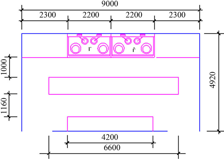
Figure 1. Simplified size plane of kitchen.
• The indoor gases are seen as incompressible.
• The gas movement within the space is stable and turbulent.
• It meets the Boussinesq assumption, which means the density is constant except for the buoyancy polynomial in the momentum equations.
• The kitchen room is well sealed and has no other air leak.
• Ignore the decentralized radiating influence of lighting bulb and other appliance.
2.3. Ventilation Parameters
The designed environment temperature is 27˚C, and the boiler power is 3.5 kW with uniform heat dissipation. The refrigerators are treated as just heat source as well as freezers, and the powers are 1019 W and 1221 W, respectively. Cooling load for human bodies is selected as working adults for 116 W each. The exhaust volume of return ports is 1.32 m3/s; only carbon dioxide gas was considered for gas pollution source, and CO2 concentration of supply air is 300 ppm while which of each boiler is 900 ppm; the initial indoor pollution level is 300 ppm. Supply air velocity is 0.25 m/s, temperature is 22˚C.
3. Performance Comparison of MV and DV
3.1. Airflow Track
Figures 2 and 3 show the indoor air flow track in 120 seconds for mixing ventilation and displacement ventilation system. We figure out that after the supply air get into the kitchen interior from both bottom sides wall, they spread out rapidly in the room and divided into two separating air streams because of the block of working bench, consequently come across the hot air plume of heat source as a result of being sucked to the upper zone of the space. Part of air is discharged from the exhaust hood vents, and the other is expelled from the top vents for DV. As for MV, the supply air enter into the space from the ceiling vents, and then, the cold conditioning air sink in due to the natural gravity, spread out at the bottom of the room, encounter the hot plume and carried to the top space.
3.2. Comfort
Under all the aspects of ventilation system performances, the thermal comfort is the most important one. And the thermal comfort obtained through the calculation of MV and DV system will be compared in the following sides: velocity distribution; temperature distribution; predicted percentage dissatisfied (PPD).
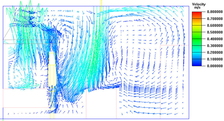
For the airflow velocity distribution (Figure 4), as it can be seen that the flow within the space which is close to the outside windows and the walls rise due to the high
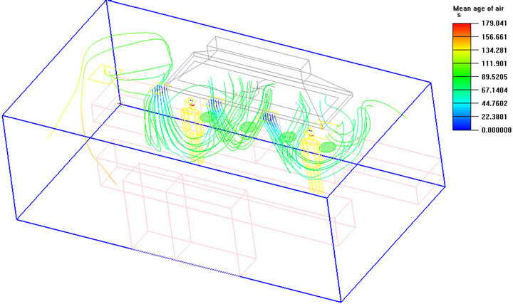
Figure 2. Airflow track for MV.
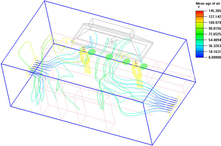
Figure 3. Airflow track for DV.
 (a)
(a)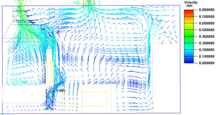 (b)
(b)
Figure 4. X = 2.9 cut plane velocity vector. (a) for MV system; (b) for DV system.
temperature of the separates in the DV system. The heat source like boiler and fridge freezer will generate massive heat plumes, which take the conditioned air in the lower zone to the upper zone. Nevertheless, the downdraft from the ceilings in the MV system seems like ejecting flow which forms the relative high-speed area. They first flow horizontally in all directions after reaching the ground, and then they go up in the same way as DV system. Generally the velocity magnitude of MV is higher than DV and the airflow characteristic of spatial pattern is cross-flow, the supply flow goes down while the other upward moves. For DV, the flow pattern goes up only among the breathing zone, however it moves up and down for MV, which definitely induces discomfort.
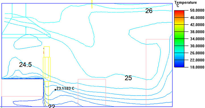
The temperature distribution on cut plane X = 4.0 for MV and DV system are shown in Figures 5(a) and (b) respectively. For DV, the temperature distribution from bottom to the top of the space increases gradually and the temperature stratification is obvious. It can be concluded that more distance space is from the supply air ports, the less temperature gradient decreases. Furthermore, the air spread in horizontal is not so apparent, and the temperature distribution in that direction is uniform relatively. For MV, temperature change in horizontal is slightly larger than DV and the temperature distribution pattern is similar to DV in general. To specially mention, the homogeneity in horizontal direction for MV cannot be assured if it’s higher speed velocity.
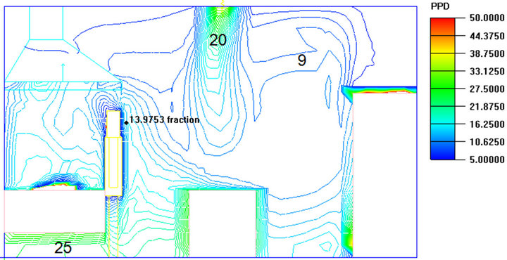
According to the acceptable three thermal environment grades and thermal comfortable standard analysis applied for the Chinese area recommended by domestic scholars for PPD index, we can see the PPD is kept below 20% as a whole, meanwhile the DV PPD overall is lower than MV (Figure 6).
 (a)
(a)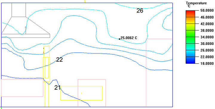 (b)
(b)
Figure 5. X = 4.0 cut plane temperature distribution. (a) for MV system; (b) for DV system.
 (a)
(a)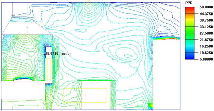 (b)
(b)
Figure 6. X = 2.9 cut plane PPD distribution. (a) for MV system; (b) for DV system.
3.3. Indoor Air Quality
This paper investigates the IAQ index in the catering kitchen through the analysis of carbon dioxide distribution, the average age of air to make the contrast study of DV and MV system.
Figures 7(a) and (b) show the CO2 distribution of cut plane X = 2.9 for MV and DV system respectively. It’s easy to find out that in DV, the airflow around the workers upward move, which means there’s no cross air infection. In the direction of south of workbench and worker there exist a higher concentration of contaminant because of the effect of block, meanwhile it won’t affect the IAQ since it’s beyond the breathing zone of humans. Yet for MV system around the area next to the vents, the pollutant concentration is particularly large, which will consequently affect the breathing air nearby. So we’ve got the conclusion that the air distribution in MV system is not so uniform as that in DV system.
The mean age of air from lower zone is less than higher zone (Figure 8), which indicates the displacement
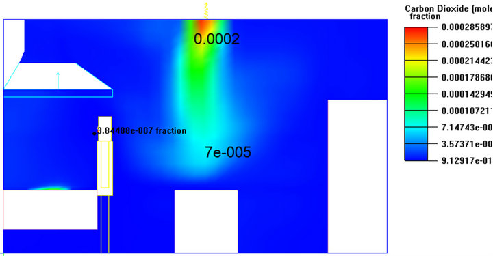 (a)
(a)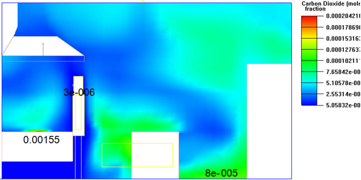 (b)
(b)
Figure 7. X = 2.9 cut plane CO2 distribution. (a) for MV system; (b) for DV system.
effect is stronger. One of the advantages for DV system is that it ensures the stagnation period of the air around the worker is less. Hence, the IAQ of the DV is better than that of MV normally with the same magnitude of flow velocity. Generally speaking, the air in the DV system has higher displacement efficiency in comparison with the air recirculation in the MV system. Moreover, as demonstrated in the figure the mean ages of air for both systems are all less than 100 seconds.
4. Summary
This paper analyses index of indoor environment quality like the distribution of air flow velocity, temperature, CO2 concentration, mean age of air, PPD in kitchen for mixing ventilation and displacement ventilation systematically for the first time. It is concluded that the DV is
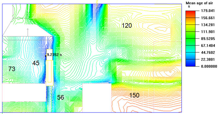 (a)
(a)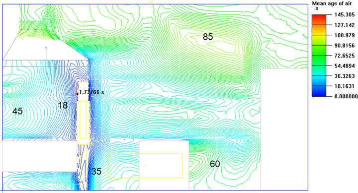 (b)
(b)
Figure 8. X = 2.9 cut plane mean age of air distribution. (a) for MV system; (b) for DV system.
better than MV no matter in the aspect of the thermal comfort or the IAQ and demonstrates the feasibility of the application of DV system into kitchen environment.
REFERENCES
- N. H. Boscawen, “Displacement Ventilation in Classrooms Report of Visit to Boscawen Elementary School”.
- A. Livchak and D. Nall, “Displacement Ventilation-Application for Humid Climate,” Clima 2000/Napoli 2001 World Congress-Napoli I., 2001, pp. 15-18.
- E. Mundt, “Convection Flows above Common Heat Sources in Rooms with Displacement Ventilation System”.
- P. O. Fanger, “Thermal Environment Human Requirements,” The Environmentalist, Vol. 6, No. 4, 1986, pp. 275-278. doi:10.1007/BF02238059
- Y. Liu and K. Hiraoka, “Ventilation Requirements for Raised Floor HVAC System,” IAQ’97 Healthy Buildings, 1997, p. 32.
- H.-J. Park and D. Holland, “The Effect of Location of a Convective Heat Source on Displacement Ventilation,” Building and Environment, Vol. 36, No. 7, 2001, pp. 883- 889. doi:10.1016/S0360-1323(01)00014-2
NOTES
*National Natural Science Foundation of China (No. 50979034).
Initial Funding for Jiangsu University Professional (No. 09JDG032).
#Corresponding author.