Journal of Computer and Communications
Vol.06 No.11(2018), Article ID:88844,15 pages
10.4236/jcc.2018.611028
Access Control Attacks on PLC Vulnerabilities
Yong Wang1, Jinyong Liu1, Can Yang1, Lin Zhou1, Shuangfei Li1, Zhaoyan Xu2
1Department of Information Security, Shanghai University of Electric Power, Shanghai, China
2Palo Alto Networks, California, CA, USA

Copyright © 2018 by authors and Scientific Research Publishing Inc.
This work is licensed under the Creative Commons Attribution International License (CC BY 4.0).
http://creativecommons.org/licenses/by/4.0/


Received: October 19, 2018; Accepted: November 26, 2018; Published: November 29, 2018
ABSTRACT
In Industrial Control Systems (ICS), security issues are getting more and more attention. The number of hacking attacks per year is endless, and the attacks on industrial control systems are numerous. Programmable Logic Controller (PLC) is one of the main controllers of industrial processes. Since the industrial control system network is isolated from the external network, many people think that PLC is a safety device. However, virus attacks in recent years, such as Stuxnet, have confirmed the erroneousness of this idea. In this paper, we use the vulnerability of Siemens PLC to carry out a series of attacks, such as S7-200, S7-300, S7-400, S7-1200 and so on. We read the data from the PLC output and then rewrite the data and write it to the PLC. We tamper with the writing of data to achieve communication chaos. When we attack the primary station, all slave devices connected to the primary station will be in a state of communication confusion. The attack methods of us can cause delay or even loss of data in the communications from the Phasor Data Concentrator (PMU) to the data concentrator. The most important thing is that our attack method generates small traffic and short attack time, which is difficult to be identified by traditional detection methods.
Keywords:
ICS, PLC, PMU, Data Tampering, Delay, Attack Methods

1. Introduction
Most of the ICS consist of several sub-components, such as PLC, Human Machine Interface (HMI), Master Terminal Unit (MTU) and Remote Terminal Unit (RTU) [1] . Due to the high reliability, simple programming, variable control program, good flexibility and convenient expansion of PLC, it has been favored by many designers of the ICS. In the power industry, PLC is used for communication operations, equipment operations, and so on. For example, the power system must ensure that the power equipment of the power plant and the substation operate synchronously. Firstly, it is necessary to ensure the consistency of the internal clock of the equipment. The safe operation of the power system requires high-precision time synchronization within a wide range. Synchronous phase measurement, power angle measurement, fault location, and fault recording of the entire power system require time synchronization technology. Safe and reliable high-precision time synchronization technology is a basic requirement for the normal operation of the smart grid in the contemporary power grid and in the future.
In this article, we use the PLC experimental equipment of Siemens. The communication protocol adopted by Siemens PLC is S7Comm protocol. It provides the service definition and protocols for real-time communication based on Ethernet [2] . At the beginning of the S7Comm protocol designer, the designer mainly focused on improving production efficiency and did not consider its security. Because PLC is the core equipment of the ICS, it has become the target of more and more hackers. A quick search in the ICS-CERT repository reveals more than 80 target PLCs out of a total of 589 advisories [3] . Many believed that PLCs are secured devices due to its isolation from the external networks of the system. The attacks such as Stuxnet have proven the incorrectness of such thoughts [1] [2] [3] [4] [5] . In addition, on December 23, 2015, the Ukrainian power grid was attacked by hackers, causing large-scale power outages, which has caused people to pay sufficient attention to communication security. In the field of information security, the most vulnerable is not the system itself, but just people. If a disgruntled engineer wants to destroy the system, a small loophole can cause devastating damage to the ICS. Therefore, the research on any tiny vulnerability also has high research value.
In this paper, we mainly carry out corresponding experimental research on PLC of Siemens. We use the Siemens PLC access control vulnerability, first establish a legal connection with the PLC, and then read and write the PLC’s intermediate register data to achieve the effect of abnormal communications. In this way, we can attack the Siemens S7 series controllers, such as S7-200, S7-300, S7-400, S7-1200 and so on. In the PLC architecture, the CPUs execute the results of the program into the intermediate registers and then execute the results. We read and rewrite the value of the intermediate register to implement the attack.
The rest of this paper is organized as follows. The related work is explained in Section 2. The test bed setup is given in Section 3 and then the attack approach on PLC based systems is introduced in Section 4. Furthermore, we discussed the lack of attack methods and corresponding emergency measures in Section 5 before where the paper is concluded in Section 6.
2. Related Work
At present, many researchers have done a lot of research work on PLC security vulnerabilities. According to [1] analysis of PLC vulnerabilities, we recognize the effectiveness of the researchers’ three attacks on PLC. And based on the Siemens PLC access vulnerability, three effective attacks were proposed: replay attack, man-in-the-middle attack and S7 Authentication Bypass Attack. Haroon Wardak et al. [3] have also explicitly proposed PLC access control vulnerabilities including poor authentication mechanisms, lack of integrity methods, defect password protection, and flawed communication protocols. Based on the access control vulnerability, the attacker can use the legal way to carry out illegal operations according to the principle of the PLC communication protocol. Moreover, this illegal operation is difficult to be identified by the general methods and corresponding measures are taken to deal with the attack. In [4] , the researchers also confirmed that Internet-oriented PLCs are more vulnerable to malicious code injection and attacks. According to the research of [6] , worms capable of spreading between PLCs have been realized. In [7] [8] , researchers conducted vulnerability analysis and attacks on PLCs on the network side. Studies presented false sequence attack that could disable the fault detection against Programmable Logic Controllers (PLCs) with partial information about the victim system are in [9] . And [10] presented a methodology of crafting an attack which exploited the Tricon configuration download phase to modify the downloaded control logic with the objective to cause common-mode failures in Tricon. In [11] , researchers proposed a firmware-level detection mechanism which can detect abnormal runtime behaviors of malicious PLC payload. The result showed that a wide variety of payload attacks could be effectively detected by the proposed approach.
The above researchers conducted related vulnerability analysis and corresponding attack experiments on PLC. Some scholars have proposed preventive measures for the corresponding vulnerabilities and attack experiments. Particularly, the worms studied in [6] are extremely destructive to PLC. However, the detection method based on PLC engineering logic static analysis proposed by [12] and the virus detection method based on dynamic analysis of debugging protocol can effectively detect it. In this paper, the I/O port can be easily operated by legal communication to achieve the intended attack purpose and will not be detected.
3. Testbed Setup
In this paper, we use Siemens PLC as the experimental equipment. The PLC uses a simple architecture. They are based on central processing modules (CPUs) and other modules that support digital inputs and outputs. The CPU executes the operating system of the PLC and runs the user program. In addition, the CPU is responsible for communicating with other devices and managing the process image. The process image stores the status of all inputs and outputs. The user program operates on the process image instead of on physical inputs and outputs. The user program runs in a loop. The CPU refreshes the process image at the beginning and end of each cycle. The biggest limit of the loop is the cycle time. If this limit is violated, the PLC will stop the user program and raise an exception.
In the PLC architecture, the CPUs execute the results of the program into the intermediate registers and then execute the results. We can program according to the format of the PLC communication protocol, establish a connection with the PLC, and read and write the value of the register. After the value of the register is overwritten, it will be executed immediately. The PLC architecture is showing in Figure 1.
Siemens PLC uses the proprietary S7Comm protocol transport block. It is a remote procedure call (RPC) protocol based on TCP/IP and ISO over TCP. The encapsulation of the protocol is showing in Figure 2.
The connection needs to be initialized when performing some functions. After the regular TCP handshake, the ISO over TCP settings continue to negotiate the PDU size. In the S7Comm protocol, the client must provide the CPU’s racks and slots for its preferred PDU size. The CPU responds with its preferred PDU size and agrees to continue using the minimum of the two values. After initialization, the client can call the functions on the CPU.
Our experimental equipment includes two Siemens S7-1200s and one Siemens LOGO. We set one of the Siemens S7-1200s as the master station in the electric power industry, and the other two devices are slaves. The IP address of the master station device is 192.168.0.200 and the master station device is recorded as A. Then the IP address of the S7-1200 slave device is 192.168.0.100 and the S7-1200 slave device is recorded as B. Last the IP address of the Siemens LOGO slave device is 192.168.0.3 and the Siemens LOGO slave device is recorded as C. Three devices communicate over Ethernet through a switch connection. The network topology is showing in Figure 3.

Figure 1. PLC Architecture, adopted from [6] .

Figure 2. Packet encapsulation, adopted from [13] .

Figure 3. The network topology.
The four devices in the picture are connected through a switch, and the computer can monitor them. The master device can communicate with the slave device and can control the input and output of the slave device.
The power system must ensure that the power equipment of the power plant and the substation operate synchronously. So, the real-time and efficient transmission of data from power industry equipment plays an important role in the safe operation of power systems. Two Siemens S7-1200 devices simulate data communications from the PMU to the data concentrator in the electric power industry. The slave takes the data from the PMU, and the slave gets the data obtained to the master. After the master gets the data from all the slaves, it transfers all the data to the data concentrator. The tested configuration is showing in Figure 4.
Our test equipment was able to perform normal data transfer and command control operations before we conduct an attack test. The slave B receives the data collected by the PMU, and then it transmits the received data to the master station A. A and B transmit data through the TSEND_C and TRCV_C modules. At first, we complete the configuration of the network related configuration. Then we download the program to the PLC. Finally, we start the running program. The data of the data block between the primary station A and the secondary station B is communicated in real time, and the data of the secondary station A data block is changed immediately after the data of the primary station A data block is changed. It is showing in Figure 5.
The upper part of the picture shows the monitoring interface of the data sending end. In addition, the remaining part shows the monitoring interface of the data receiving end. When we modify the data in the modified item of the data sender, the data of the receiver will be updated in real time.
The output of the slave station C is controlled by A to simulate the control function of the industrial control system. We let A’s output Q0.2 be the input of C to control the indicator light. First, we can program Master A with TIA software and configure the configuration network. Then configure the network configuration for C with LOGO! Soft Comfort software. Finally, we download the program and run the PLC. The slave C takes the output of the master station A as its own input. When the Q0.2 of the master station A is one, the slave station C is lit red. It is showing in Figure 6.
When we press the control button of the master station, the output value of the master station Q0.2 is 1. When we press the control button of the master station, the output value of the master station Q0.2 is 1. Therefore, when the master station output Q0.2 is 1, the output of the master station controls the input of the slave station, and the slave station indicator lights.

Figure 4. The testbed configuration.
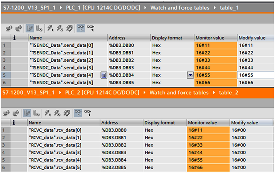
Figure 5. Data transmission.

Figure 6. A and C control experiments.
4. The Attack Approach
We understand PLC access control vulnerabilities and use them for attacks. As an attacker, we must have the ability to automatically recognize the PLC and successfully establish a connection with the PLC. When we detect the IP address, we can automatically identify whether it is the PLC that we are looking for. In this paper, we establish a connection with the detected PLC IP address to detect whether it is the type of PLC we want. Since the tool we use to establish a connection with the PLC can only be connected to the PLC of a manufacturer, when we can successfully establish a connection with the searched IP address, it is the target we want to attack, otherwise we will abandon the attack operation on this IP. When we establish a connection with the target, we first read the value of the PLC input and output. According to the environment in the real industrial control system, we have different effects on the 0 or 1 of the input and output ports of the PLC. Therefore, we invert the read data and write the inverted value to the PLC register to make the PLC output abnormal. We repeat the above operation in a loop until the PLC stops running. The attack process is showing in Figure 7.
In our attack method, the most critical step is to establish a connection with the PLC according to the principle of S7Comm protocol. According to the principle of the S7Comm protocol, we write a program to establish a connection. The format of the message sent by the program to the PLC is the same as that of the S7Comm protocol.
4.1. Scanning
For an attacker, once it is activated in a specific environment, the first thing is to lock the target. After starting the program, the program starts scanning the port and IP. The connection result is tested one by one. We attack the PLCs that can connect successfully, assuming that the industrial control system equipment PLC is in the same network segment. After starting to attack the system, the local IP is first identified. We search all open port (102) IPs in the local IP network segment. In this paper, the experimental device port is 102, so this experiment takes port (102) as an example. The scanner can be broken down into the following steps:
Get local IP and port;
Calculate IPs of the subnet;
Set up TCP connection;
Save valid IP and port;
Stop scanning and disconnect TCP connection.
Some of the main procedures and results are showing in Figure 8 and Figure 9.
In the program, we define a function to find the IP. The initial IP we use is a local IP to get the IP of the device quickly. In the defined function, we first use the socket function to connect with the new IP. If it detects that the device port is 102, we store this IP. In the eighth line of the program, we record a valid IP address and print it. Otherwise, launch the connection and regain the new IP address for the next iteration.
In the results of the program, the first line shows the local IP, and the rest are IPs that conform to the standard. It can be seen that the IP addresses of the three devices in this experiment have been searched.
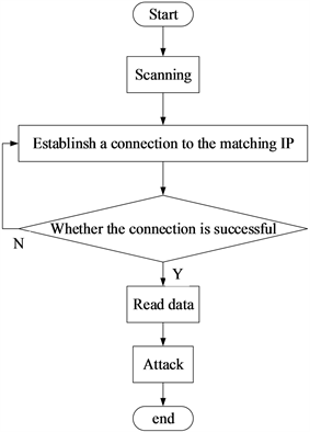
Figure 7. The attack process.

Figure 8. The main procedures.

Figure 9. IP results.
4.2. Establish Connection
According to the previous section, we have searched for valid IPs. We will connect according to the valid IP address we scanned. We try to establish a connection with the PLC using the socket library function in python. This method is always actively disconnected by the PLC when the program is running, so the method can only be used for IP scanning. We finally use the python-snap7 tool to connect to the PLC. The main connection procedure is showing in Figure 10.
After getting a valid IP address, we establish a connection with the device with a valid IP address. In the set function to establish a connection, the fourth line obtains the port number, slot number, and IP of the device and establishes a connection with the device. If the device successfully establishes a connection, the program on the sixth line will show that the connection was successful. Otherwise, the connection fails, the program executes the eighth line of exception handling code.
We connect to the PLC using the scanned IP and port number. In addition, according to the goal we set, we need to set the rack number and slot number of the number target before establishing the connection. In this paper, our experimental equipment is Siemens S7-1200, so the rack number and slot number we set are zeros in the program. The library function we use performs a three-way handshake with the PLC according to the S7Comm protocol principle. If the connection is successful, the program will return a message that the connection was successful.
4.3. Read Data
When establishing a connection, we need to set the IP, port, rack number and slot number. Similarly, when we read the data of the PLC intermediate register, we need to set the function code and intermediate register absolute address according to the S7Comm protocol communication protocol. For Siemens S7-1200, the function codes for registers I, Q, M and DB are 0x81, 0x82, 0x83 and 0x84 respectively. For a controller, the output of the controller controls the operation of the industrial equipment. Therefore, for an attacker, it is possible to attack the controller and make its control confusing, thereby destroying the normal operation of the device to achieve maximum damage. Therefore, an attacker is more concerned with the output of the controller. We read the value of the output and convert the read hexadecimal number and store it in the database. The main program for reading data is showing in Figure 11.
Under the premise that we have established a connection with the device, we can communicate with the device normally. Then, before we read the device data, we first establish a connection with the database to store the data of the reading device, as shown in the fifth line of the program. In the eighth line of the program, we first get the data register area of the device to be read. Next, the device data is read in the ninth line of the program. Finally, in the tenth line of the program, when we parse the data we read, we convert the data into text form.

Figure 10. The main connection.


Figure 11. In the program, first connect with the PLC, read the value of the PLC output port, and write the value into the database.
4.4. Attack
In industrial control systems, the constant start and stop of equipment in the industry can cause great or even devastating damage to the service life of the equipment. In the previous steps, we have read the controller’s output value, reversed the read value and wrote it to the controller. During the attack cycle, we perform an attack every 10 ms, resulting in less traffic making the general detection method unrecognizable.
After we start the attack, this action will continue until the controller stops running. In industrial control systems, equipment operation and shutdown play a critical role in the normal operation of the entire system. When we implemented the attack, if the device is running properly, we will let it stop running. And if the device is in a stopped state, we let the device start running by attack. Through our attacks, the device is frequently in an abnormal state, which will cause devastating damage to the device. What’s worse, this kind of attack can even cause great harm to the person.
In the power grid, data acquisition has high requirements for real-time performance, and the delay or loss of collected data will cause great damage to the normal operation of the entire power grid. In this article, we used two Siemens PLCs for data transmission experiments. When we started the attack, the data transmission was abnormal. The receiver does not receive data. If the data on the acquisition side is constantly changing, the receiver will lose a lot of data. When we attack, abnormal data transmission is showing in Figure 12 and Figure 13.
The figure shows the short monitoring interface for data transmission. The current monitoring value is hexadecimal 0.
At the same time, the data of the transmitting end of the device is 0 in hexadecimal, but the data of the receiving end is still not changed, and the data transmission of the device is delayed.
We can make the synchronous sampling data transmission delay or even lose data through our attack method. However, this type of attack is easily identified by traditional detection methods and corresponding measures are taken. The equipment clock of the power system and the phase, power angle, fault location and fault recording data of the power system collected by the synchronous measurement technology play a very important role in the normal operation of the power system. Therefore, the synchronously sampled data cannot be subjected to any errors or even slight errors during the transmission. So, we use the attack method of changing a certain data to attack the synchronous sampling technology. This attack method can not only cause the power system to malfunction, but also the traffic generated by the attack method is small and is not easily recognized by the traditional detection method. A screenshot of the tampering data success is showing in Figure 14.

Figure 12. Data sender monitoring interface.

Figure 13. Data receiving terminal monitoring interface.

Figure 14. The original data 88 was successfully changed to 64 and sent to the receiving end.
5. Discussion
The power system must ensure that the power equipment of the power plant and the substation operate synchronously. First, it is necessary to ensure the consistency of the internal clock of the equipment. The safe operation of the power system requires high-precision time synchronization within a wide range. Synchronous phase measurement, power angle measurement, fault location, and fault recording of the entire power system of the power system require time synchronization technology. The basic principle of the PMU is that the filtered AC signal is quantized by the A/D converter, and the microprocessor calculates the phasor according to the algorithm. Data is transferred to the remote data concentrator via a dedicated channel. The data concentrator collects information from each PMU to provide data for system-wide monitoring, protection, and control. In the process of synchronous sampling data transmission, there are many factors that cause data transmission delay, tampering or even loss. We use two PLCs to mimic the master and slave of the data transmission. And we use our attack method to attack the primary station and the secondary station, resulting in serious consequences of delay, tampering and even loss during data transmission.
In this paper, our PLC attack method has limitations. The attack method we designed is not infectious and cannot be transmitted between PLCs. Although we can change the value of the PLC’s intermediate register and cause a lot of damage to the power grid, the attack method we designed was to rewrite the data of the PLC intermediate register through python-snap7, but failed to read and write the OB block data of the PLC and change the sampling clock. In the future, we should be able to read and write the OB block data of the PLC through in-depth study of the S7Comm protocol.
6. Securing PLC Systems
At the beginning of the system design, the designer considered functional safety without considering information security. Therefore, we must take some measures to make up for the existing problems. In order to improve the security of data transmission, we propose to add a Secure Hash Algorithm 2 (SHA2) in the data transmission message part. In this way, the device calculates the hash value using the same algorithm. If the hash value calculated by the device is the same as the hash value transmitted, the data is accepted, otherwise the data packet is discarded.
In order to prevent attackers from reading and writing device data at will, we propose a user management strategy. A legal user list is stored in the device, and the device can automatically discard the data of the illegal user.
7. Conclusions
In the power grid, PLC (the core equipment of the power grid) as the main controller has become the object of many hackers. Both the PLC vulnerability researched by researchers and the PLC vulnerability announced by Siemens’ official website have appeared a lot. Since industrial control systems work in the internal network, our well-known PLC access control vulnerabilities have not been paid enough attention. However, once our attack method is used by internal engineers, it will also cause catastrophic damage to the industrial control system.
In this paper, we confirm that this vulnerability can cause huge damage to the system through the USB drive. Therefore, it is very important to take some safety measures. In order to protect a PLC system, some security measures should be adopted. The most important of these is the lack of identity authentication in the system. Therefore, any user can establish a connection with the PLC according to the correct protocol principle and perform some column operations. So, it is very urgent to add data encryption transmission and user management mechanism to improve the security of the system. We currently only have these simple defenses that still fall short of the system’s security requirements. Because it is easy to break through these defensive measures to the Stuxnet, security research in this area is still an interesting research area in the future.
Conflicts of Interest
The authors declare no conflicts of interest regarding the publication of this paper.
Cite this paper
Wang, Y., Liu, J.Y., Yang, C., Zhou, L., Li, S.F. and Xu, Z.Y. (2018) Access Control Attacks on PLC Vulnerabilities. Journal of Computer and Communications, 6, 311-325. https://doi.org/10.4236/jcc.2018.611028
References
- 1. Sandaruwan, G.P.H., Ranaweera, P.S. and Oleshchuk, V.A. (2013) PLC Security and Critical Infrastructure Protection. 2013 IEEE 8th International Conference on Industrial and Information Systems, Peradeniya, 17-20 December 2013, 81-85. https://doi.org/10.1109/ICIInfS.2013.6731959
- 2. Yang, M. and Li, G. (2014) Analysis of S7COMM PROTOCOL IO Communication Protocol. 2014 Fourth International Conference on Instrumentation and Measurement, Computer, Communication and Control, Harbin, 945-949. https://doi.org/10.1109/IMCCC.2014.199
- 3. Wardak, H., Zhioua, S. and Almulhem, A. (2016) PLC Access Control: A Security Analysis. 2016 World Congress on Industrial Control Systems Security (WCICSS), London, 12-14 December 2016, 1-6. https://doi.org/10.1109/WCICSS.2016.7882935
- 4. Klick, J., Lau, S., Marzin, D., Malchow, J. and Roth, V. (2015) Internet-Facing PLCs as a Network Backdoor. 2015 IEEE Conference on Communications and Network Security (CNS), Florence, 28-30 September 2015, 524-532. https://doi.org/10.1109/CNS.2015.7346865
- 5. Chien, E., Falliere, N. and Murchu, L.O. (2011) W32.Stuxnet Dossier. https://www.symantec.com/content/en/us/enterprise/media/security_response/whitepapers/w32_stuxnet_dossier.pdf
- 6. Spenneberg, R., Brüggemann, M. and Schwartke, H. (2016) PLC Blaster: A Worm Living Solely in the PLC. OpenSource Security Ralf Spenneberg.
- 7. Milinkovic, S.A. and Lazic, L.R. (2012) Industrial PLC Security Issues. 2012 20th Telecommunications Forum (TELFOR), Belgrade, 20-22 November 2012, 1536-1539. https://doi.org/10.1109/TELFOR.2012.6419513
- 8. Ylmaz, E.N., Ciylan, B., Gonen, S., Sindiren, E. and Karacayilmaz, G. (2018) Cyber Security in Industrial Control Systems: Analysis of DoS Attacks against PLCs and the Insider Effect. 2018 6th International Istanbul Smart Grids and Cities Congress and Fair (ICSG), Istanbul, 25-26 April 2018, 81-85. https://doi.org/10.1109/SGCF.2018.8408947
- 9. Xiao, M., Wu, J., Long, C. and Li, S. (2016) Construction of False Sequence Attack against PLC Based Power Control System. 2016 35th Chinese Control Conference (CCC), Chengdu, 27-29 July 2016, 10090-10095. https://doi.org/10.1109/ChiCC.2016.7554953
- 10. Lim, B., Chen, D., An, Y., Kalbarczyk, Z. and Iyer, R. (2017) Attack Induced Common-Mode Failures on PLC-Based Safety System in a Nuclear Power Plant: Practical Experience Report. 2017 IEEE 22nd Pacific Rim International Symposium on Dependable Computing (PRDC), Christchurch, 22-25 January 2017, 205-210. https://doi.org/10.1109/PRDC.2017.34
- 11. Yang, H., Cheng, L. and Chuah, M.C. (2018) Detecting Payload Attacks on Programmable Logic Controllers (PLCs). 2018 IEEE Conference on Communications and Network Security (CNS), Beijing, 30 May-1 June 2018, 1-9.
- 12. Liao, X.D., Xie, R.Y. and Yu, Y.L. (2018) Study on the Characteristics Analysis and Detection Method of New PLC Virus. Information Technology, No. 3, 62-66.
- 13. SNAP7. S7 Protocol. [Online] http://snap7.sourceforge.net/siemens_comm.html#s7_protocol