Paper Menu >>
Journal Menu >>
 J. Software Engineering & Applications, 2008, 1: 68-75 Published Online December 2008 in SciRes (www.SciRP.org/journal/jsea) Copyright © 2008 SciRes JSEA Towards Automatic Transformation from UML Model to FSM Model for Web Applications Xi Wang, Huaikou Miao, Liang Guo School of Computer Engineering and Science, Shanghai University, Shanghai, 200072, China Email: {w_whitecn, hkmiao, glory}@shu.edu.cn Received November 17 th , 2008; revised November 26 th , 2008; accepted November 30 th , 2008. ABSTRACT The need for automatic testing of large-scale web applications suggests the use of model-based testing technology. Among various modeling languages, UML is widely spread and used for its simplicity, understandability and ease of use. But rigorous analysis for UML model is difficult due to its lack of precise semantics. On the other hand, as a formal notation, FSM provides an avenue for automatic generation of test cases, but the requirement for mathematical basis makes itself academic inventions divorced from real applications. This paper proposes an approach to transforming UML model to FSM model, taking advantage of both languages. As our work focuses on the transformation of UML state diagrams to FSM models, a specific transformation mechanism is presented, which deals with different elements with different mapping rules. To illustrate the mechanism we proposed, an example of a web application for software download is presented. Finally, we give a method for implementation of the mechanism and a tool prototype to support the method. Keywords: UML Model, FSM Model, Model transformation 1. Introduction Providing greater assurance that the software is of high quality and reliability, testing has been considered more and more important as people gradually realize the great effect on their daily life made by software products. Hand-crafted methods are acceptable until the coming of age when there are full of large-scale manufactures with high complexity, especially the appearance of web applications which labeled for their additional heterogeneity, concurrency and distribution. Web applications are usually composed of front-end user interfaces, back-end servers including web servers, application servers and database servers, which build up a new way for deploying software applications. Components called for supporting task completion of web applications by each server may be programmed in different languages and executed on different platforms. In addition, web applications are frequently modified due to continuous updates of its components, high-speed developing technologies and changes of the needs of its users. All of these characteristics are challenging the traditional testing method which largely depends on the testers. On the other hand, most companies keep the minimum amount of time as their primary priority to meet market demand while customers pay their much attention to the reduction of the cost during maintenance, leading directly to the calls for effective testing within a relative short period of time. Generation of test cases is the main task of testing; since detections of faults are operated by comparing expect outputs with actual ones obtained from running of these test cases. Model-based testing, which involves developing and using a model describing the structural and behavioral aspects of the system to generate test cases automatically, is an effective method for testing various software artifacts including web applications. As the models are developed early in the cycle from requirements information [1], the generation of test cases can be conducted in parallel with the implementation of the System Under Test (SUT), rather than sequentially, saving the time supposed to be spent for waiting. Also, it supports re-use in future testing as these models capture the behavior of a software system and in contrast to a test suite, they are much easier to update if the specification changes [2]. The critical part of model-based testing is the construction of models. Among various modeling languages, UML has been widely spread and used in industry for its simplicity and ease of use. It enables modelers to address all the views needed to analyze and develop the corresponding system. Further more, as a visual language, it can clearly show the structure and functions of the system, facilitating understanding and communication between designers, modelers, developers  Towards Automatic Transformation from UML Model to FSM Model for Web Applications 69 Copyright © 2008 SciRes JSEA and users. Besides, many powerful tools have been developed and used to support UML modeling such as argoUML. But unfortunately, it is widely acknowledged that UML can hardly provide formal semantics, as it comprises several different notations with no formal semantics attached to the individual diagrams. Therefore, it is not possible to apply rigorous automated analysis or to execute a UML model in order to test its behavior, short of writing code and performing exhaustive testing [3]. As one of the formal notations, FSM (Finite State Machine) provides a significant opportunity for testing because it precisely describes what functions the software is supposed to provide in a form that can easily be manipulated by automated means [4]. Being applied to the testing process, its relative theory could be helpful and supported for enhancing efficiency. Furthermore, in addition to traditional software, a web application’s behavior could also be modeled using FSMs theoretically and then test cases could be automatically generated by traversing the path through the FSM model of the application, with each distinct path comprising a single test case [5]. Besides, FSM model can be visualized to tell intuitively the direction to which a test case is going, since state-based specification languages are fairly easy to translate into a specification graph as they have natural graph representations [4]. Last, the transformation to FSM facilitates model checking which verifies certain property of the model. However, its requirement for mathematical basis limits the range of utilization. This paper proposes a method for transformation from UML model to FSM model, taking advantage of both: the simplicity and intelligibility of UML and the accuracy and derivability of FSM. It also enables the reuse of the existing and well-established tools for UML and theories for FSM. There’re several kinds of diagrams within UML corresponding to different views of the system, our job focuses on the transformation of state diagram, as it is most often used to model the behavior of an individual object. The remainder of this article is organized as follows: Section 2 reviews existing works in transformation of UML models. Section 3 presents a transformation mechanism from UML state diagrams to FSM models. To illustrate the transformation mechanism, an example of transforming from a state diagram representing a web application for software download is given in Section 4. In section 5, a method for implementing the transformation mechanism we proposed is given, together with a brief introduction to a tool prototype based on this method. Finally, concluding remarks and discussions about future works are presented in section 6. 2. Related Works Automatic testing has become a hot spot in the software engineering field for facilitating development process of software products. But most of the current technologies are based on “capture/replay” mechanism, which costs too much time and manual works while recording testing scenarios and handling with small changes on the functional design or user interfaces. Tools running on this mechanism will not design or generate test cases themselves and will not provide any instruction on the coverage situation of the generated test cases. Further more, there are even fewer automatic testing tools for web applications which requires for even more automatism. Most of the present tools [13] do not support the function test of web applications including Link Checks for checking links of the web application, HTML Validators for providing standard HTML syntax validation, Web Functional/Regression Test Tools, Web Site Security Test Tools, Load and Performance Test Tools and etc. Since most of them rely on information obtained from codes of the web applications and only concentrate on verification of static aspects, we need a tool to help verifying the behavior of them while paying least price. With the appearance and popularity of the concept of object-oriented and model-driven, model-based testing for software products has aroused much attention in industry. Though many researches are done in this field, tools developed under their theories still have certain gaps with applying to real uses due to their lack of systematism and low automatic level [14,15,16,17,18,19]. Construction of models is the beginning of model-based testing for web applications. The most common one is to use Entity Relation Diagrams or UML Class Diagrams to model web pages of a web application and relationships between them. Isakowitz et al describe web applications with a method called Relationship Management Methodology [20]. Coda et al proposes a model WOOM for modeling web applications in a higher level of abstraction [21]. Gellersen et al introduce the WebComposition Markup Language for implementing a model for Web application development called Web Composition [22]. Conallen et al extend UML modeling language to model the structure of web applications [23]. However, these methods rarely construct models on the behavioral and functional aspects of the web applications and few testing approaches are figured out for these models. The model language we use when designing the web applications is UML which strongly supports users to describe complicated software including web applications. But till now, no such complete testing tool has ever been implemented as its semi-formal semantics prevents it from automatic testing. On the other hand, many methods for generation of test cases from formal models are presented. [24] generates test cases from an Object- Oriented Web Test Model which is a combination of Object Relation Diagram, Page Navigation Diagram, Object State Diagram, Block Branch Diagram and Function Cluster Diagrams, but it will be trapped if there are too many objects in the software. Ricca et al models  70 Towards Automatic Transformation from UML Model to FSM Model for Web Applications Copyright © 2008 SciRes JSEA web applications by modeling for each web page and obtain test cases according to proposed rules. Still, it would only be useful dealing with simple applications [5,25], models web applications with FSM which will then be used for test cases generation by search for different path of the model under different criteria. Considering that FSM model is also the most common used object for model checking, we choose it for destination of our model transformation process and origin for test cases generation. Formalization of UML models has aroused much attention in industry. One of the most active group is the precise UML group [6], which is made up of international researchers who are interested in providing a precise and well-defined semantics for UML, by using model-oriented notations, such as Z or VDM. There are also works done by other researchers, Borges et al. [7] integrate UML class diagrams and a formal specification language OhCircus by written UML elements in terms of OhCirus. Latella et al. [8] converts UML state diagrams into the formal language Promela. Traore et al. [9] proposes a transformation mechanism from UML state diagrams to PVS which facilitates automatic model checking. However, few researches on the transformation to the FSM model can be found. Erich et al. [11] gives a hierarchical finite state machine model for state diagrams, which is capable of acquiring the hierarchical information, but it does not mention the method for transformation to FSM models with the removal of hierarchy. [10] transforms time-extended UML state diagram into timed automata, but special elements of the state diagram are not under its consideration. The method we proposed enables the transformation of state diagrams with special elements, such as completion transition, fork, join and history state. Besides, the flatness of the resulting FSM model can greatly support the automation of the generation of test cases. 3. Transformation Mechanism from UML State Diagram to FSM Model As UML and FSM are source and target models of the transformation mechanism respectively, a brief introduction of both is given below. 3.1 UML The Unified Modeling Language (UML) is becoming a standard language for specifying, constructing and documenting the artifacts of a software-intensive system. It can model from different perspectives with several kinds of diagrams that express static and dynamic aspects of a system. As a visualized model, UML conveys information intuitively to our human beings who can get better understanding through graphics. Besides, it is easy to learn and use, making it more attractive to those who model. Because of the characteristics mentioned above UML severs as the ideal model for describing the real. Class diagram, object diagram, use case diagram, sequence diagram, communication diagram, activity diagram and state diagram are the most commonly used diagrams in UML. Class and object diagrams model the static design view of a system, mostly about relationships between objects, while rest of them focus on dynamic aspects. For the purpose of capturing unexpected outputs, we obtain most of the information needed for testing from behavioral models. As one of the behavioral models, state diagram is often used to model the life cycle of certain object, from its motivation to termination. Since most systems involve more than one object, state diagrams are considered to be the minimal unit for representing behaviors. We therefore begin our research with UML state diagrams. 3.2 UML State Diagram State diagram, which has been mainly discussed in this paper, specifies the sequences of situations an object goes through during its lifetime in response to events, together with its responses to those events. Many elements are involved for expressing semantics of the diagram. States represent certain situations the object stays, each with a name for distinguishing itself from others. There are several types of states within state diagrams. States that have no substructures are called simple states, others are called composite states. A composite state may contain nested states either concurrent or sequential which are called orthogonal substates and nonorthogonal substates respectively. Given a set of nonorthogonal substates in the context of an enclosing composite state called OR-state, the object is said to be in the composite state and in only one of those substates at a time [12]. In the case of orthogonal substates, the concept of region is introduced which specifies each state machine that execute in parallel in the context of the enclosing composite state called AND-state. Only one substate from each of the orthogonal regions is active as long as the object remains in the corresponding AND- state. Initial state indicates the default starting place for the state diagram or substate while final state indicates that the execution of the state machine or the enclosing state has been completed. Another special state is the history state which allows an OR-state to remember the last substate that was active prior to the leaving from the OR-state. Transitions are relationships between a pair of states indicating that an object in the first state will enter the second state when a specified event occurs under certain condition. Therefore, a transition t comprises three parts: source state denoted by src(t) which is the state affected by the transition; target state denoted by dst(t) which the object enters after the completion of the transition; label denoted by EGA(t) which contains events, guards, and actions.  Towards Automatic Transformation from UML Model to FSM Model for Web Applications 71 Copyright © 2008 SciRes JSEA Semantics of transitions varies according to its source and target state. When leading out of a composite state, a fired transition leaves the active nested states before leaving the composite one. When targeting a composite sate, a fired transition would lead the object to the initial state of each nested machine running in parallel after entering the composite state. In addition to these regular transitions, there exist some special ones. Completion transition is a transition with no event trigger, the fire of which depends on the completion of the behavior within its source state. Transition join which sources multiple states allows the object to leave all the orthogonal regions of an AND-state at one time. Similarly, transition fork which targets multiple states enables passing directly to all the orthogonal regions of an AND-state. The initial state of the regions which have no target states of the fork will be activated. With clear semantics of each element, the transformation mechanism which deals with different elements with different mapping rules can be determined. 3.3 FSM Model Finite State Machines (FSM) are models each built with a set of states, as well as transitions going from one state to another, which are triggered either by inputs from outside or changes within the system itself. The execution would start from a state called start state and keep running until reaching a state called accept state. As its mathematic nature, we can establish a formal representation for FSM which is the target model during the transformation process for facilitating automation. Definition1. A FSM (Finite State Machine) A is a quintuple (Q, L, δ δδ δ , q 0 , q), where Q is a finite set of states of A, L is a finite set of transition labels of A, δ δδ δ : Q×L→ →→ → Q is the transition function relating two states by the transition going between them, q 0 ∈ ∈∈ ∈Q is the start state, q∈ ∈∈ ∈Q is the accept state. If transition t∈ ∈∈ ∈ δ δδ δ represented as (s, l, s ′ ′′ ′ ), then source (t) = s, target (t) = s ′ ′′ ′ , label (t) = l. 3.4 Transformation from State Diagram to FSM Model As can be seen from the definition of FSM model, states involved are all basic ones, indicating that the removal of hierarchy is needed during the transformation process. For the sake of being conformed to the semantics of original models, the hierarchical relations between states of the state diagram should be obtained as critical information for generating corresponding FSM model without hierarchy. We therefore take the translation of topological structures of state diagrams to mathematic models of Hierarchical Finite State Machines (HFSM) as a preliminary step towards model transformation due to the fact that HFSM provides a simple and precise manner to illustrate the topological structure of a state diagram. Different from FSM, HFSM contains states with inner structures. We could take HFSM as parallel and/or hierarchical composition of FSMs with states of higher hierarchy representing FSMs of lower hierarchy. A definition of HFSM is given bellow according to this point of view. Definition2. Given a finite set of FSMs F = {A 1 ,.., A n } with mutually distinct state spaces Q(A i ), φ φφ φ : U UU U A ∈ ∈∈ ∈ F Q(A) → →→ → P(F) is a composition function on F iff − ∃ 1 A∈F ∧ A∉U ran(φ), which indicates a unique root FSM denoted by φ root − ∀A∈U ran(φ) • ∃ 1 s∈U A′∈F\ {A} Q(A′) • A∈φ(s) − ∀S ⊆ U A∈F Q(A) • ∃s∈S • S ∩ U A∈φ (s) Q(A) = ∅. Definition3. Hierarchical finite state machine (HFSM) is a pair (F, φ φφ φ ) where F is a set of FSMs with mutually distinct state spaces, φ φφ φ is a composition function on F. With the definition of HFSM, the topological structure of the original state diagram could be obtained in a formal representation, which is specified by the composition function φ φφ φ . Construction of such structure starts from the top hierarchy, and then gradually comes to completion by detailing each composite state that belongs to the state diagram level by level. Establish φ φφ φ (s) = A i and F = F ∪ ∪∪ ∪ {A i } if the composite state s is an OR-state with a sub-machine A i enclosed, while φ φφ φ (s) = {A 1 , A 2 ,…, A n } and F = F∪ ∪∪ ∪{A 1 }∪ ∪∪ ∪{A 2 }∪ ∪∪ ∪…∪ ∪∪ ∪{A n } if the composite state s is an AND-state with sub-machines A 1 , A 2 ,…, A n each located in the corresponding orthogonal region of s. The state pointed by initial state turns to be the start state of the corresponding FSM, while the state which points at final state becomes the accept state. Once the representation for topological structure is present, we can get to know the hierarchical relation between states which can be specified by the following function. When given a HFSM (F, φ φφ φ ): χ : U A∈F Q(A) → P ( U A∈F Q(A)) χ (s) = {s′ | ∃A∈F • A∈φ (s) ∧ s′∈Q(A)} With hierarchical information represented in mathematic form, the transformation to the resulting FSM model starts from that of transitions of the original state diagram. But some preliminary conceptions have to be introduced first. Definition4. A set C ⊆ U A∈F Q(A) is a configuration of a given HFSM (F, φ φφ φ ) iff −∃ 1 s∈Q(φ root ) • s∈C −s∈C ∧ A∈φ(s) ⇒ ∃ 1 s′∈Q(A) • s′∈C −s∈C ∧ ∃ s′ • s ∈χ(s′) ⇒ s′∈C Definition5. Given a HFSM (F, φ φφ φ ) with C as the set of all its configurations and s as one of its states, function config: U A∈F Q(A) → P (U A∈F Q(A)) config (s) = { ci | ci ⊆ C ∧ s∈ci } Definition6. Given a HFSM (F, φ φφ φ ), the default configuration of certain state sd is denoted as a function deconfig: U A∈F Q(A) → P (U A∈F Q(A)) deconfig (sd) = X ⇔ ∃ 1 X : config (sd) • ∀s • ( s∈X ∧ sd∉χ*(s) ⇒ I q 0 (φ i (s)) ⊆ X ) 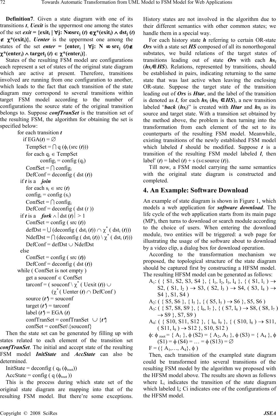 72 Towards Automatic Transformation from UML Model to FSM Model for Web Applications Copyright © 2008 SciRes JSEA Definition7. Given a state diagram with one of its transitions t, Uexit is the uppermost one among the states of the set exit = {exit i | || | ∀ ∀∀ ∀j: N• •• • src j (t) ∈ ∈∈ ∈χ χχ χ*(exit i ) ∧ ∧∧ ∧ dst j (t) ∉ ∉∉ ∉ χ χχ χ*(exit i )}, Uenter is the uppermost one among the states of the set enter = {enter i | || | ∀ ∀∀ ∀j: N • •• • src j (t)∉ ∉∉ ∉ χ χχ χ*(enter i ) ∧ ∧∧ ∧ target j (t) ∈ ∈∈ ∈ χ χχ χ*(enter i )}. States of the resulting FSM model are configurations each represent a set of states of the original state diagram which are active at present. Therefore, transitions involved are running from one configuration to another, which leads to the fact that each transition of the state diagram may correspond to several transitions within target FSM model according to the number of configurations the source state of the original transition belongs to. Suppose confTranSet is the transition set of the resulting FSM, the algorithm for obtaining the set is specified below: for each transition t if EGA(t) = ∅ TempSet = I q (φ i (src (t))) for each q i ∈ TempSet config i = config (q i ) ConfSet = I config i DefConf = deconfig ( dst (t)) if t is a join for each s i ∈ src (t) config i = config (s i ) ConfSet = I config i DefConf = deconfig ( dst (t )) if t is a fork ∧ dst (t) > 1 ConfSet = config ( src (t)) defDst = U (deconfig ( dst i (t)) ∩ χ * ( dst i (t))) NdefDst = I (deconfig ( dst i (t)) \ χ * ( dst i (t))) DefConf = defDst ∪ NdefDst else ConfSet = config ( src (t)) DefConf = deconfig ( dst (t)) while ( ConfSet is not empty ) get a souconf ∈ ConfSet tarconf = ( souconf \ χ * ( Uexit (t)) ∪ (χ * ( Uenter (t) ∩ DefConf ) source (t ′ ′′ ′ ) = souconf target (t ′ ′′ ′ ) = tarconf label (t ′ ′′ ′ ) = EGA (t) confTranSet = confTranSet ∪ {t ′ ′′ ′ } confSet = confSet\{souconf} Then the state set can be generated by filling up with states related to each element of the transition set confTranSet. The initial and accept state of the resulting FSM model InitState and AccState can also be determined. InitState = deconfig ( q 0 (φ root )) AccState = config ( q (φ root )) This is the process during which state set of the original state diagram are mapping into that of the resulting FSM model. But there’re some exceptions. History states are not involved in the algorithm due to their different semantics with other common states; we handle them in a special way. For each history state h referring to certain OR-state Ors with a state set HS composed of all its nonorthogonal substates, we build relations of the target states of transitions leading out of state Ors with each hs i (hs i ∈ ∈∈ ∈HS). Relations, represented by transitions, should be established in pairs, indicating returning to the same state that was last active when leaving the enclosing OR-state. Suppose the target state of the transition leading out of Ors is Htar, and the label of the transition is denoted as l, for each hs i (hs i ∈ ∈∈ ∈HS), a new transition labeled “back (hs i )” is created with Htar and hs i as its source and target state. With a transition set obtained by the method above, the problem is then turning into the transformation from each element of the set to its counterparts of the resulting FSM model. Meanwhile, existing transitions of the newly established FSM model which labeled l should be modified. Suppose t is a transition of the resulting FSM model labeled l, then label′ (t) = label (t) + s (s∈source (t)). Till now, a FSM model carrying the same semantics with the original state diagram is constructed and completed. 4. An Example: Software Download An example of state diagram is shown in Figure 1, which models a web application for software download. The life cycle of the web application starts from its main page (MP), then turns to download or search module according to the choice of users. When entering the download module, two entities will be triggered: a web page for illustrating the usage of the software about to download by a video clip, a dialog box for download operation. According to the transformation mechanism we proposed, the topological structure of the state diagram should be captured first by constructing a HFSM model. The resulting HFSM model can be generated as follows: A 1 : ( { S1, S2, S3, S4 }, { l 1 , l 2 , l 3 , l 4 }, { ( S1, l 1 ) → S2, ( S1, l 2 ) → S3, ( S2, l 3 ) → S4, ( S3, l 4 ) → S4 }, S1, S4 ) A 2 : ( { S5, S6 }, { l 5 }, { ( S5, l 5 ) → S6 }, S5, S6 ) A 3 : ( { S7, S8, S9 }, { l 6 , l 7 }, { ( S7, l 6 ) → S8, ( S8, l 7 ) → S9 }, S7, S9 ) A 4 : ( { S10, S11, S12 }, { l 8 , l 9 }, { ( S10, l 8 ) → S11, ( S11, l 9 ) → S12 }, S10, S12 ) φ: φ root = { A 1 }, φ (S2) = { A 2 , A 3 }, φ (S3) = { A 4 }, φ (S1) = φ (S4) = … = φ (S13) = ∅ F = ({ A 1 ,…, A 4 }, φ ) Then, each transition of the exampled state diagram could be transformed into several transitions of the resulting FSM model by the algorithm we proposed with the HFSM model above. The results are shown as follows where L i indicates the transition of the state diagram which labeled l i ; Ci indicates one of the configurations of the HFSM model.  Towards Automatic Transformation from UML Model to FSM Model for Web Applications 73 Copyright © 2008 SciRes JSEA L 1 : C1 = { root, S1}, C2 = { root, S2, S5, S7 }, ( C1, l 1 ) → C2 L 2 : C3 = { root, S3, S10 }, ( C1, l 2 ) → C3 L 3 : C4 = { root, S2, S6, S9 }, C5 = { root, S4 }, ( C4, l 3 ) → C5 L 4 : C6 = { root, S3, S11 }, C7 = { root, S3, S12 }, ( C3, l 4 ) → C5, ( C6, l 4 ) → C5, ( C7, l 4 ) → C5 L 5 : C8 = { root, S2, S5, S8 }, C9 = {root, S2, S5, S9 }, C10 = { root, S2, S6, S7 }, C11 = { root, S2, S6, S8,}, C12 = {root, S2, S6, S9 }, ( C2, l 5 ) → C10, ( C8, l 5 ) → C11, ( C9, l 5 ) → C12 L 6 : ( C2, l 6 ) → C8, ( C10, l 6 ) → C11 L 7 : ( C8, l 7 ) → C9, ( C11, l 7 ) → C12 L 8 : ( C3, l 8 ) → C6 L 9 : ( C6, l 9 ) → C7 L 10 : ( C1, l 10 ) → C8, ( C1, l 10 ) → C11 L 11 : C13 = { root, S13 }, ( C12, l 11 ) → C13 L 12 : ( C7, l 12 ) → C2 L 13 : ( C6, l 13 ) → C13 We can now generate the state set of the resulting FSM model, which is filled up with all the configurations mentioned above: Q = { C1,…, C13}. The initial state is C1 while the accept state is C5. Finally, noticing there’s a history state H within the state S3, we should add several new transitions to the transition set of the FSM model: ( C5, “back (S10)” ) → C3, ( C5, “back (S11)” ) → C6, ( C5, “back (S12)” ) → C7 Meanwhile, transitions labeled l 4 should be modified into: ( C3, l 4 (S10)) → C5, ( C6, l 4 (S11)) → C5, ( C7, l 4 (S12)) → C5. 5. Implementation of the Transformation Mechanism As automatic testing is our final goal of model transformation, the implementation of such mechanism by computer itself is required. The method proposed in this section can be applied to all the diagrams of UML model, only the transformation mechanism varies when dealing with different kinds. Since computers are unable to understand and analyze meanings conveyed by diagrams, texts carrying equivalent amount of information would help. Here, we choose XMI. 5.1 XMI XML Metadata Interchange (XMI) is a standard that enables users to express objects using Extensible Markup Language (XML), the universal format for representing data on the WWW. As a bridge across the gap of objects and XML, it provides a standard mapping from objects defined by UML to XML, fulfilling object-oriented feature of both UML and programming languages. In addition, many mature tools supporting transformation from UML diagrams to corresponding XMI files are presented, such as argoUML. Therefore, XMI becomes the ideal textual representation of those UML diagrams. 5.2 Implementation Method First of all, XMI files are needed which can be easily obtained as output of argoUML with inputs as UML diagrams. As shown in Figure 2, when receiving the resulting XMI, we extract semantics by recognizing different tags which indicate the location of information related to certain elements of the UML diagrams. Then, data structure based on the corresponding HFSM model could be constructed. With topological information provided by the data structure, mapping rule for transforming to FSM models works. Finally, resulting models are made to be hold in XML files with schema defined by ourselves. A tool prototype has been developed to support our transformation mechanism and implementation method. It takes state diagrams carried by XMI files as inputs and resulting FSM model carried by XML files as output. Also, one can modify the chosen XMI file through an edition platform provided by the tool before transformation operation starts. Figure 1. State diagram of a web application for software download  74 Towards Automatic Transformation from UML Model to FSM Model for Web Applications Copyright © 2008 SciRes JSEA Figure 2. Implementation process 5.3 Simulation For the purpose of verifying the correctness of our approach, we use the tool developed by ourselves to simulate the example presented in the previous section. Figure 3 shows an interface of our tool for automatic testing for web applications. The characters in the main frame are the textual representation of the exampled state diagram. After choosing transformation function of the tool, the model will then be transformed into FSM model written in XML language, as shown in Figure 4. Figure 3. An interface of the tool for automatic testing for web applications Figure 4. FSM model written in XML language To illustrate the resulting FSM model more clearly, our tool implements the visualization of its textual representation, which can be seen in Figure 5. 6. Conclusions This paper proposes a method for transformation from UML model to FSM model. It allows users to model a system with the language they used to without barriers towards automatic and efficient testing. As we focus on the translation of state diagrams, a specific transformation mechanism is proposed which enables generation of corresponding FSM models with same semantics. Modelers create one state diagram for each object of the system and other UML diagrams for relations between them. Since our specific transformation mechanism serves for every single state diagram, synthesis of the FSM models each obtained from one of these state diagrams should be discussed. It depends on the information provided by other UML diagrams like class diagrams, sequence diagrams etc. Besides, these UML diagrams themselves need to be transformed into FSM with meta-model we defined so as to generate target model that covers information carried in all of the given UML models. They could either be transformed directly into FSM models, or to state diagrams as the first step, which would then come into FSM models by the mechanism we proposed. Experiments about comparison on efficiencies of both should be hold with complete transition mechanisms before the choice can be made. Besides, details of elements contained in labels including event, guard and action, as well as the action attribute of states, are not considered in our research, their affections to the correctness of transformation is also a part of the future work. Figure 5. The visualization of the model’s textual representation model level HFSM model UML diagrams implementation level XMI files FSM models XML files semantic extraction semantic extraction t opological information topological information semantic extraction transformation mechanism s e mantic ex tr action data structure for HFSM model transformation mechanism save as save as  Towards Automatic Transformation from UML Model to FSM Model for Web Applications 75 Copyright © 2008 SciRes JSEA 7. Acknowledgement This work has been supported by National High- Technology Research and Development Program of China under grant No. 2007AA01Z144, Natural Science Foundation of China under grant No. 60673115, National Grand Basic Research Program of China under grant No. 2007CB310800, Research Program of Shanghai Education Committee under grant No. 07ZZ06 and Shanghai Leading Academic Discipline Project, Project Number: J50103. REFERENCES [1] S. R. Dalal, A. Jain, N. Karunanithi, and B. M. Horowitz, “Model-based testing in practice,” Proceedings of the 21st International Conference on Software Engineering, Los Angeles, California, United States, pp. 285–294, May 1999. [2] H. Robinson, “Graph theory techniques in model-based testing,” International Conference on Testing Computer Software, 1999. [3] W. E. McUmber and B. H. C. Cheng, “A general framework for formalizing UML with formal languages,” Proceeding of the 23rd international conference on Software engineering, Toronto, Canada, pp. 433–442, 2001. [4] J. Offutt, S. Y. Liu, A. Abdurazik, and P. Ammann, “Generating test data from state-based specifications,” The Journal of Software Testing, Verification, and Reliability, pp. 25–53, 2003. [5] C. J. Mallery, “On the feasibility of using FSM approaches to test large web applications,” May 2005. [6] The precise group, http://www.cs.york.ac.uk/puml/. [7] R. M. Borges and A. C. Mota, “Integrating UML and formal methods,” Electronic Notes in Theoretical Computer Science, Elsevier Science Publishers, pp. 97–112, July 2007. [8] D. Latella, I. Majzik, and M. Massink, “Automatic verification of a behavioral subset of UML Statechart diagrams using the SPIN model-checker,” Formal Aspects of Computing, pp. 637–664, 1999. [9] I. Traore, “An outline of PVS semantics for UML statecharts,” Journal of Universal Computer Science, 2000. [10] M. Z. Lai and J. Y. You, “Formalize the time-extended UML state chart with timed automata,” Computer Applications, pp. 4–6, August 2003. [11] E. Mikk, Y. Lakhnech, and M. Siegel, “Hierarchical automata as model for statecharts,” Proceedings of the 3rd Asian Computing Science Conference on Advances in Computing Science, pp. 181–196, 1997. [12] G. Booch, J. Rumbaugh, and I. Jacobson, “The unified modeling language user guide,” China Machine Press, Beijing, 2006. [13] R. Hower, “Web site test tools and site management tools,” Software QA and Testing Resource Center, 2002. [14] Belinfante, L. Frantzen, and C. Schallhart, “Tools for Test Case Generation,” Model-based Testing of Reactive Systems, Springer LNCS 3472, Springer-Verlag, pp. 391–438, 2005. [15] M. Utting, A. Pretschner, and B. Legeard, “A taxonomy of model-based testing,” Technical Report 04/2006, Department of Computer Science, The University of Waikato (New Zealand), April 2006. [16] I. K. El-Far and J. A. Whittaker, “Model-based software testing,” Encyclopedia of Software Engineering, Wiley-InterScience, Vol. 1, pp. 825–837, 2002. [17] M. Blackburn, R. Busser, and A. Nauman, “Why model-based test automation is different and what you should know to get started,” in International Conference on Practical Software Quality and Testing, 2004. [18] B. Legeard, F. Peureux, and M. Utting, “Controlling test case explosion in test generation from B formal models,” The Journal of Software Testing, Verification and Reliability, 14(2): pp. 81–103, 2004. [19] A. Pretschner, H. Lötzbeyer, and J. Philipps, “Model based testing in evolutionary software development,” IEEE International Workshop on Rapid System Prototyping 2001, pp. 155–161, 2001. [20] T. Isakowitz, E. A. Stohr, and P. Balasubramanian, “RMM: A methodology for structured hypermedia design,” Communication of the ACM, Vol. 38, No. 8, August 1995. [21] F. Coda, C. Ghezzi, G. Vigna, and F. Garzotto, “Towards a software engineering approach to web site development,” Proceedings of 9th International Workshop on Software Specification and Design, Ise-Shima, Japan, April 16–18, 1998. [22] H. Gellersen and M. Gaedke, “Object-oriented web application development,” IEEE Internet Computing, January–February 1999. [23] J. Conallen, “Modeling web application architectures with UML,” Communications of the ACM, Vol. 42, No. 10, October 1999. [24] D. C. Kung, C. H. Liu, and P. Hsia, “An object-oriented web test model for testing web applications,” First Asia-Pacific Conference on Quality Software, pp. 30–31, October 2000. [25] F. Ricca and P. Tonella, “Analysis and testing of web applications,” Proceedings of the 23rd International Conference on Software Engineering, pp.12–19, May 2001. |