Paper Menu >>
Journal Menu >>
 Int. J. Communications, Network and System Sciences, 2010, 3, 213-252 doi:10.4236/ijcns.2010.33031 blished Online March 2010 (http://www.SciRP.org/journal/ijcns/). Copyright © 2010 SciRes. IJCNS Pu Advances in MIMO Techniques for Mobile Communications—A Survey Farhan Khalid, Joachim Speidel Institute of Telecommunications, University of Stuttgart, Stuttgart, Germany Email: {khalid, speidel}@inue.uni-stuttgart.de Received December 2, 2009; revised January 5, 2010; accepted Febr uary 6, 2010 Abstract This paper provides a comprehensive overview of critical developments in the field of multiple-input multi- ple-output (MIMO) wireless communication systems. The state of the art in single-user MIMO (SU-MIMO) and multiuser MIMO (MU-MIMO) communications is presented, highlighting the key aspects of these technologies. Both open-loop and closed-loop SU-MIMO systems are discussed in this paper with particular emphasis on the data rate maximization aspect of MIMO. A detailed review of various MU-MIMO uplink and downlink techniques then follows, clarifying the underlying concepts and emphasizing the importance of MU-MIMO in cellular communication systems. This paper also touches upon the topic of MU-MIMO ca- pacity as well as the promising convex optimization approaches to MIMO system design. Keywords: Multiple-Input Multiple-Output (MIMO), Multiuser MIMO, Wireless Communications, Beam- forming, Diversity, Precoding, Capacity 1. Introduction Multiple-input multiple-output (MIMO) wireless systems employ multiple transmit and receive antennas to in- crease the transmission data rate through spatial multi- plexing or to improve system reliability in terms of bit error rate (BER) performance using space-time codes (STCs) for diversity maximization [1]. MIMO systems exploit multipath propagation to achieve these benefits, without the expense of additional bandwidth. More re- cent MIMO techniques like the geometric mean decom- position (GMD) technique proposed in [2] aim at com- bining the diversity and data rate maximization aspects of MIMO in an optimal manner. These advantages make MIMO a very attractive and promising option for future mobile communication systems especially when com- bined with the benefits of orthogonal frequency-division multiplexing (OFDM) [3,4]. The capacity of an M N single-user MIMO (SU- MIMO) system with M transmit and N receive antennas, in terms of the spectral efficiency i.e. bits per second per Hz, is given by [1] 2 log detH N CM IHH (1) where H is the N M MIMO channel matrix and ρ is the signal to noise ratio (SNR) at any receive antenna. Equa- tion (1) assumes that the M information sources are un- correlated and have equal power. Expressed in terms of the eigenvalues, Equation (1) can be written as [1] 2 1 log 1 m i i CM (2) where λi represent the nonzero eigenvalues of HHH or HHH for N ≤ M and M < N respectively and m = min(M, N). Therefore, MIMO systems are capable of achieving several-fold increase in system capacity as compared to single-input single-output (SISO) systems by transmit- ting on the spatial eigenmodes of the MIMO channel. Equation (2) also shows that the performance of MIMO systems is dependent on the channel eigenvalues. Very low eigenvalues indicate weak transmission chan- nels which may make it difficult to recover the informa- tion from the received signals. Optimal power allocation based on the water-filling algorithm can be used to maxi- mize the system capacity subject to a to tal transmit pow- er constraint. Water-filling provides substantial capacity gain when the eigenvalue spread, i.e., the cond ition num- ber λmax/λmin is sufficiently large. The MIMO concept becomes even more attractive in multiuser scenarios where the network capacity can be increased by simultaneously accommodating several users  F. KHALID ET AL. 214 without the expense of valuable frequency resources. This paper is arranged as follows: Section 2 provides an overview of the current wireless standards which sup- port MIMO technologies. Sections 3 and 4 include de- tailed discussion and performance analysis of various important SU-MIMO and multiuser MIMO (MU-MIMO) techniques respectively that are proposed for the next generation wireless communication systems. In-depth description of several MU-MIMO uplink and downlink schemes is given in Section 4 followed by a brief discus- sion of the MU-MIMO capacity. Section 5 provides an overview of convex optimization which has become an important tool for designing optimal MIMO beamform- ing systems. Section 6 concludes this work and identifies the areas for future research. 2. Current Implementation Status There has been a lot of research on MIMO systems and techniques. MIMO-O FDM WLAN products based on the IEEE 802.11n standard are already available. The IEEE 802.16 wireless MAN standard known as WiMAX also includes MIMO features. Fixed WiMAX services are being offered by operators worldwide. Mobile WiMAX networks based on 802.16e are also being deployed while 802.16m is under development. IEEE 802.20 mo- bile broadband wireless access (MBWA) standard is also being formulated which will have complete support for mobility including high-speed mobile users e.g., on train networks. For other applications like cellular mobile com- munications which supports both voice and data traffic, MIMO systems are yet to be deployed. However, the 3GPP’s long term evolution (LTE) is under development and adopts MIMO-OFDM, orthogonal frequency-divi- sion multiple access (OFDMA) and single-carrier frequ- ency-division multiple access (SC-FDMA) transmission schemes. The following text presents a more detailed dis- cussion of the various technical aspects of these stand- ards and technologies. 2.1. IEEE 802.11n Wi-Fi The IEEE 802.11n WLAN standard incorporates MIMO- OFDM as a compulsory feature to enhance data rate. Ini- tial target was to achieve data rates in excess of 100 Mb/s [5]. However, current WLAN devices based on 802.11n Draft 2.0 a re capable of ac hi eving thro ug h put u p t o 30 0 Mb/s utilizing two spatial streams in a 40 MHz channel in the 5 GHz band [6]. Initially, there were two main proposals one form the WWiSE consortium and the other from the TGnSync consortium competing for adoption by the IEEE 802.11 TGn. However, another proposal by the Enhanced Wire- less Consortium (EWC) was finally accepted as the first draft for IEEE 802.11n [7]. The IEEE 802.11n standard proposes the use of the legacy 20 MHz channel and also an optional 40 MHz channel. The available modulation schemes include BPSK, QPSK, 16-QAM and 64-QAM [5,6]. Convolu- tional coding with different code rates is specified and use of low-density parity-check (LDPC) codes is also supported [5,8]. The MIMO techniques adopted include both spatial multiplexing and diversity techniques. Open-loop MIMO (OL-MIMO) techniques which do not require channel state information (CSI) at the transmitter seem to have been preferred [9]. Non-iterative linear minimum mean square error (LMMSE) detection has primarily been considered so as to minimize the com- plexity associated with MIMO detection while ensuring reasonably good performance [10]. Spatial spreading mentioned in [11] is an open-loop MIMO spatial multiplexing technique where multiple data streams are transmitted such that the diversity is maximized for each of the streams. The MIMO diversity techniques introduced in the standard include space-time block coding (STBC) and cyclic shift diversity (CSD) which extend the range and reception of 802.11n devices. In addition, conventional receiver spatial diversity tech- niques like maximum ratio combining (MRC) are also specified. Transmit beamforming is also specified as an optional feature [6]. The Cisco Aironet 1250 series ac- cess point based on 802.11 n draft 2.0 supports op en-loop transmit beamforming [12]. 802.11n draft 2.0 specifies a maximum of 4 spatial streams per channel. Thus, a maximum throughput of 600 Mb/s can be achieved by using 4 spatial streams in a 40 MHz channel. In addition to spatial multiplexing and doubled channel bandwidth, more efficient OFDM with shorter guard interval (GI) and new medium access con- trol (MAC) layer enhancements (e.g. closed-loop rate adaptation [13]) have also contributed to the increased throughput of 802.11n [6]. 2.2. IEEE 802.16 WiMAX The IEEE 802.16 worldwide interoperability for micro- wave access (WiMAX) is a recently developed wireless MAN standard that employs MIMO spatial multiplexing and diversity techniques. In addition to fixed WiMAX, the IEEE 802.16e Mobile WiMAX standard has also been developed and was approved in December 2005 [14]. Fixed WiMAX networks have already been de- ployed around the world and Mobile WiMAX deploy- ments have also started. 802.16e-2005 is basically an amendment to the 802.16-2004 stand ard for fixed WiMAX with addition of new features to support mobility. 802.16e specifies the 2–6 GHz frequency band for mobile applications and the 2–11 GHz band for fixed applications (The single-carrier WirelessMAN-SC PHY specification for fixed wireless Copyright © 2010 SciRes. IJCNS  F. KHALID ET AL. 215 access however specifies the 10–66 GHz frequency band [15].). It also specifies a license-exempt band between 5–6 GHz. A cellular network structure is specified with support for handoff s and mobile users moving at vehicu- lar speeds are also supported, thus enabling mobile wire- less internet access [14,16]. In addition to single carrier transmission, the standard specifies OFDM transmission scheme with 128, 256, 512, 1024 or 2048 subc arrier s. Both TDD and FDD duplex ing is specified while the multiplexing/multiple access schemes include OFDMA in addition to burst TDM/ TDMA. However, scalable OFDMA is specified in all mobile WiMAX profiles as the physical layer multiple access technique. The various channel bandwidths speci- fied in the standard include 1.25, 1.75, 3.5, 5, 7, 10, 8.75, 10, 14 and 15 MHz. WiMAX supports adaptive modula- tion and coding schemes. The supported modulation schemes include BPSK, QPSK, 16-QAM and 64-QAM [14,16]. Optional 256-QAM support is provided in the WirelessMAN-SCa PHY [15]. Convolutional codes at rate1/2, 2/3, 3/4 or 5/6 are specified as mandatory for both uplink and downlink. In addition, convolutional turbo codes, repetition codes, LDPC and concatenated Reed-Solomon convolutional code (RS-CC ) are specified as optional. The supported data rates range from 1 Mb/s to 75 Mb/s [14,16]. IEEE 802.16e supports both open-loop and closed- loop MIMO. Open-loop MIMO techniques include spa- tial multiplexing (SM) and space-time coding (STC) [14,17,18]. 802.16e includes support for up to four spa- tial streams and therefore a maximum of 4 4 MIMO configuration [14,18]. STC is based on the Alamouti scheme (also STBC) and is also called space-time trans- mit diversity (STTD). It is an optional feature and may be used to provide higher order transmit diversity on the downlink [14]. In closed-loop MIMO, full or partial CSI is available at the transmitter through feedback. Eigenvector steering is employed to approach full capacity of the MIMO channel and water filling can be used to maximize throughput by allocating power in an optimal manner [9,19]. IEEE 802.16e supports closed-loop MIMO pre- coding for SM and also closed-loop STC [14,17]. How- ever, closed-loop MIMO is not yet su ppor ted in the latest WiMAX Forum Wave 2 profiles [18]. Another MIMO mode called “collaborative spatial multiplexing” is also specified where two subscriber stations (SS), each hav- ing a single antenna, use the same subchannel for uplink transmission in order to increase the throughput [14,15, 17,20]. The adaptive antenna systems (AAS) supported in 802.16e also include closed-loop adaptive beamforming, which us es feed back fro m the S S to the b ase sta tion (BS ) to optimize the down link transmission [14,15,18]. IEEE 802.16 Task Group m (TGm) has also been set up to develop the IEEE 802.16m standard which will enable interoperability between WiMAX and 3GPP’s Long Term Evolution (LTE) standard for next genera- tion mobile communications [21,22]. 802.16m is ex- pected to support high-speed mobile wireless access (up to 350 km/h) and peak data rates of over 300 Mb/s us- ing 4 4 MIMO [22]. 2.3. IEEE 802.20 MBWA The IEEE 802.20 working group was established to draft the IEEE 802.20 Mobile Broadband Wireless Ac- cess (MBWA) standard which is also nicknamed as MobileFi. IEEE 802.20 proposes a complete cellular structure and is designed and optimized for mobile data services at speeds up to 250 km/h. However, it can also support voice services due to very low transmission latency of 10–30 ms (better than the 25–40 ms for 802.16e). User data rates in excess of 1 Mb/s can be supported at 250 km/h [23–25]. MBWA is designed to operate in the licensed bands below 3.5 GHz [24,25]. 2.5 MHz to 20 MHz of up- link/downlink transmission bandwidth can be allocated per cell [25]. For a bandwidth of 5 MHz, peak aggregate data rate of around 16 Mb/s can be supported in the downlink [23,24] which obviously would be much greater for higher bandwidths. The transmission scheme is based on OFDM, with OFDMA used for downlink transmission while both OFDMA and code-division multiple access (CDMA) are specified for the uplink. Rotational OFDM is specified as an optional scheme. The standard supports both FDD and TDD operation. The supported modulation schemes in- clude QPSK, 8-PSK, 16-QAM and 64-QAM. Support of hierarchical (layered) modulation involving the superpo- sition of two modulation schemes is also included for broadcast and multicast services. The specified FEC coding schemes include convolutional codes, turbo codes and LDPC codes [25 ]. Various MIMO schemes are also supported. STTD (based on STBC) and SM are specified for SU-MIMO transmission, utilizing up to 4 transmit antennas. STTD is particularly important for high speed mobile access. Two different stream multiplexing schemes namely sin- gle codeword (SCW) and multiple codeword (MCW) may be employed for MIMO transmission. These sche- mes also support closed-loop MIMO downlink transmis- sion with rank adaptation. Both schemes utilize linear precoding at the BS for transmit beamforming based on the feedback of a suitable precoding matrix from the user equipment’s (UE’s) codebook to the BS. The standard also supports MU-MIMO or space-division multiple ac- cess (SDMA) transmission in the downlink which in- volves multiuser scheduling and precoding at the BS depending upon the feedback of the preferred precoding matrix index and differential channel quality indicator Co pyright © 2010 SciRes. IJCNS 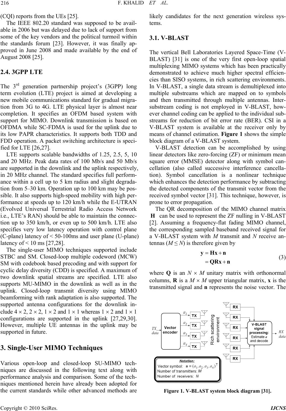 F. KHALID ET AL. 216 (CQI) reports from the UEs [25]. The IEEE 802.20 standard was supposed to be avail- able in 2006 but was delayed du e to lack of support from some of the key vendors and the political turmoil within the standards forum [23]. However, it was finally ap- proved in June 2008 and made available by the end of August 2008 [25]. 2.4. 3GPP LTE The 3rd generation partnership project’s (3GPP) long term evolution (LTE) project is aimed at developing a new mobile communications standard for gradual migra- tion from 3G to 4G. LTE physical layer is almost near completion. It specifies an OFDM based system with support for MIMO. Downlink transmission is based on OFDMA while SC-FDMA is used for the uplink due to its low PAPR characteristics. It supports both TDD and FDD operation. A packet switching architecture is speci- fied for LTE [26,27]. LTE supports scalable bandwidths of 1.25, 2.5, 5, 10 and 20 MHz. Peak data rates of 100 Mb/s and 50 Mb/s are supported in the downlink and the uplink respectively, in 20 MHz channel. The standard specifies full perform- ance within a cell up to 5 km radius and slight degrada- tion from 5–30 km. Operation up to 100 km may be pos- sible. It also supports high-speed mobility with high per- formance at speeds up to 120 km/h while the E-UTRAN (Evolved Universal Terrestrial Radio Access Network i.e., LTE’s RAN) should be able to maintain the con nec- tion up to 350 km/h, or even up to 500 km/h. LTE also specifies very low latency operation with control plane (C-plane) latency of < 50-100ms and user p lane (U-plane) latency of < 10 ms [27,28]. The single-user MIMO techniques supported include STBC and SM. Closed-loop multiple codeword (MCW) SM with codebook based precoding and with support for cyclic delay diversity (CDD) is specified. A maximum of two downlink spatial streams are specified. LTE also supports MU-MIMO in the downlink as well as in the uplink. Closed-loop transmit diversity using MIMO beamforming with rank adaptation is also supported . The supported antenna configurations for the downlink in- clude 4 2, 2 2, 1 2 and 1 1 whereas 1 2 and 1 1 configurations are supported in the uplink [27,29,30]. However, multiple UE antennas in the uplink may be supported in future. 3. Single-User MIMO Techniques Various open-loop and closed-loop SU-MIMO tech- niques are discussed in the following text along with performance analysis and compariso n. Some of the tech- niques mentioned herein have already been adopted for the current standards while other advanced methods are likely candidates for the next generation wireless sys- tems. 3.1. V-BLAST The vertical Bell Laboratories Layered Space-Time (V- BLAST) [31] is one of the very first open-loop spatial multiplexing MIMO systems which has been practically demonstrated to achieve much higher spectral efficien- cies than SISO systems, in rich scattering environments. In V-BLAST, a single data stream is demultiplexed into multiple substreams which are mapped on to symbols and then transmitted through multiple antennas. Inter- substream coding is not employed in V-BLAST, how- ever channel coding can be applied to the individual sub- streams for reduction of bit error rate (BER). CSI in a V-BLAST system is available at the receiver only by means of channel estimation. Figure 1 shows the simple block di agram of a V-BLAST system. V-BLAST detection can be accomplished by using linear detectors like zero-forcing (Z F) or mini mum me an square error (MMSE) detector along with symbol can- cellation (also called successive interference cancella- tion). Symbol cancellation is a nonlinear technique which enhances the detection performance by subtracting the detected components of the transmit vector from the received symbol vector [31]. This technique, however, is prone to error propagation. The QR decomposition of the MIMO channel matrix can be used to represent the ZF nulling in V-BLAST [2]. Assuming a frequency-flat fading MIMO channel, the corresponding sampled baseband received signal for a V-BLAST system with M transmit and N receive an- tennas (M ≤ N) is therefore given by H yHxn QRxn (3) where Q is an N M unitary matrix with orthonormal columns, R is a M M upper triangular matrix, x is the transmitted signal and n represents the noise vector. The Figure 1. V-BLAST system block diagram [31]. Copyright © 2010 SciRes. IJCNS 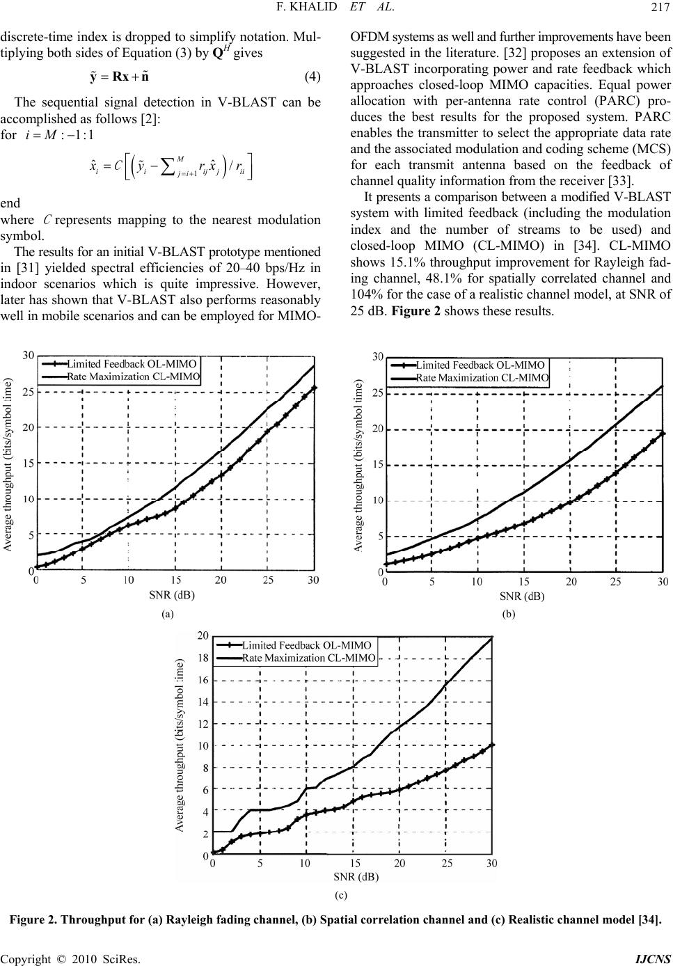 F. KHALID ET AL. Copyright © 2010 SciRes. IJCNS 217 ii discrete-time index is dropped to simplify notation. Mul- tiplying both sides of Equation (3) by QH gives yRxn (4) The sequential signal detection in V-BLAST can be accomplished as follows [2]: for :1:1iM 1 ˆˆ / M ii ijj ji x yrx C r end where represents mapping to the nearest modulation symbol. C The results for an initial V-BLAST prototype mentioned in [31] yielded spectral efficiencies of 20–40 bps/Hz in indoor scenarios which is quite impressive. However, later has shown that V-BLAST also performs reasonably well in mobile scenarios and can be employed for MIMO- OFDM system s as well and furt her impro vements ha ve been suggested in the literature. [32] p roposes an extension of V-BLAST incorporating power and rate feedback which approaches closed-loop MIMO capacities. Equal power allocation with per-antenna rate control (PARC) pro- duces the best results for the proposed system. PARC enables the transmitter to select the appropriate data rate and the associated modulation and coding scheme (MCS) for each transmit antenna based on the feedback of channel quality information from the receiver [33]. It presents a comparison between a mod ified V-BLAST system with limited feedback (including the modulation index and the number of streams to be used) and closed-loop MIMO (CL-MIMO) in [34]. CL-MIMO shows 15.1% throughput improvement for Rayleigh fad- ing channel, 48.1% for spatially correlated channel and 104% for the case of a realistic channel model, at SNR of 25 dB. Figure 2 shows these results. (a) (b) (c) Figure 2. Throughput for (a) Rayleigh fading channel, (b) Spatial cor rel ation channe l and (c ) Realistic c hannel model [34]. 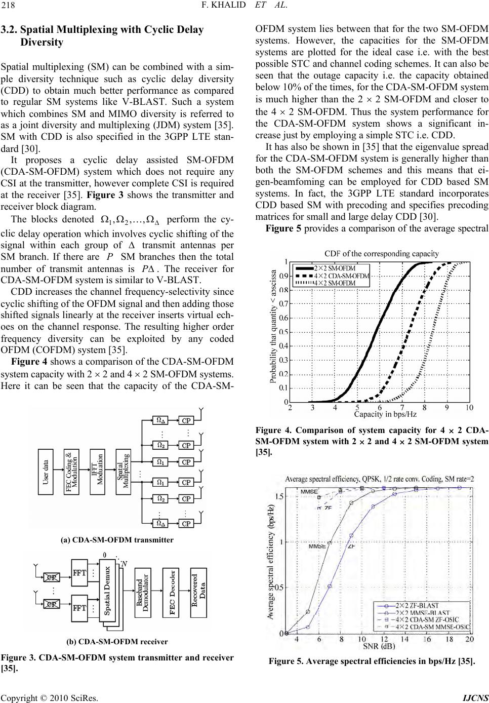 F. KHALID ET AL. 218 3.2. Spatial Multiplexing with Cyclic Delay Diversity Spatial multiplexing (SM) can be combined with a sim- ple diversity technique such as cyclic delay diversity (CDD) to obtain much better performance as compared to regular SM systems like V-BLAST. Such a system which combines SM and MIMO diversity is referred to as a joint diversity and multiplexing (JDM) system [35]. SM with CDD is also specified in the 3GPP LTE stan- dard [30]. It proposes a cyclic delay assisted SM-OFDM (CDA-SM-OFDM) system which does not require any CSI at the transmitter, however complete CSI is required at the receiver [35]. Figure 3 shows the transmitter and receiver block diagram. The blocks denoted perform the cy- clic delay operation which involve s cyclic shifting of the signal within each group of ,,, 21 transmit antennas per SM branch. If there are P SM branches then the total number of transmit antennas is P . The receiver for CDA-SM-OFDM system is similar to V-BLAST. CDD increases the channel frequency-selectivity since cyclic shifting of the OFDM signal and then adding those shifted signals linearly at the receiver inserts virtual ech- oes on the channel response. The resulting higher order frequency diversity can be exploited by any coded OFDM (COFDM) system [35]. Figure 4 shows a comparison of the CDA-SM-OFDM system capacity with 2 2 and 4 2 SM-OFDM systems. Here it can be seen that the capacity of the CDA-SM- (a) CDA-SM-OFDM transmitter (b) CDA-SM-OFDM receiver Figure 3. CDA-SM-OFDM system transmitter and receiver [35]. OFDM system lies between that for the two SM-OFDM systems. However, the capacities for the SM-OFDM systems are plotted for the ideal case i.e. with the best possible STC and channel coding schemes. It can also be seen that the outage capacity i.e. the capacity obtained below 10% of the times, for the CDA-SM-OFDM system is much higher than the 2 2 SM-OFDM and closer to the 4 2 SM-OFDM. Thus the system performance for the CDA-SM-OFDM system shows a significant in- crease just by employing a simple STC i.e. CDD. It has also be shown in [35] that the eigenvalue spread for the CDA-SM-OFDM system is generally higher than both the SM-OFDM schemes and this means that ei- gen-beamfoming can be employed for CDD based SM systems. In fact, the 3GPP LTE standard incorporates CDD based SM with precoding and specifies precoding matrices for small and large delay CDD [30]. Figure 5 provides a comparison of the average spectral Figure 4. Comparison of system capacity for 4 2 CDA- SM-OFDM system with 2 2 and 4 2 SM-OFDM system [35]. Figure 5. Average spectral efficiencies in bps/Hz [35]. Copyright © 2010 SciRes. IJCNS 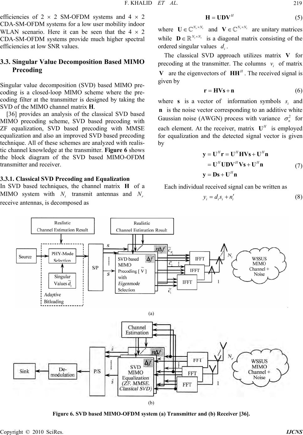 F. KHALID ET AL. 219 efficiencies of 2 2 SM-OFDM systems and 4 2 CDA-SM-OFDM systems for a low user mobility indoor WLAN scenario. Here it can be seen that the 4 2 CDA-SM-OFDM systems provide much higher spectral efficiencies at low SNR values. 3.3. Singular Value Decomposition Based MIMO Precoding Singular value decomposition (SVD) based MIMO pre- coding is a closed-loop MIMO scheme where the pre- coding filter at the transmitter is designed by taking the SVD of the MIMO channel matrix H. [36] provides an analysis of the classical SVD based MIMO precoding scheme, SVD based precoding with ZF equalization, SVD based precoding with MMSE equalization and also an improved SVD based precoding technique. All of these schemes are analyzed with realis- tic channel knowledge at the transmitter. Figure 6 shows the block diagram of the SVD based MIMO-OFDM transmitter and receiver. 3.3.1. Classical SVD Precoding and Equalization In SVD based techniques, the channel matrix of a MIMO system with transmit antennas and receive antennas, is decomposed as H t Nr N H HUDV (5) where and are unitary matrices while rt NN U tt NN tt NN V D is a diagonal matrix consisting of the ordered s i ngular v alues . i d The classical SVD approach utilizes matrix for precoding at the transmitter. The columns of matrix are the eigenvectors of V i v V H HH . The received signal is given by rHVsn (6) where is a vector of information symbols si s and is the noise vector correspond ing to an additive white Gaussian noise (AWGN) process with variance n2 n for each element. At the receiver, matrix H U is employed for equalization and the detected signal vector is given by HH H HH H H y UrUHVs Un UUDVVs Un yDsUn (7) Each individual received signal can be written as iii ydsn i (8) (a) (b) Figure 6. SVD based MIMO-OFDM system (a) Transmitter and (b) Receiver [36]. Co pyright © 2010 SciRes. IJCNS 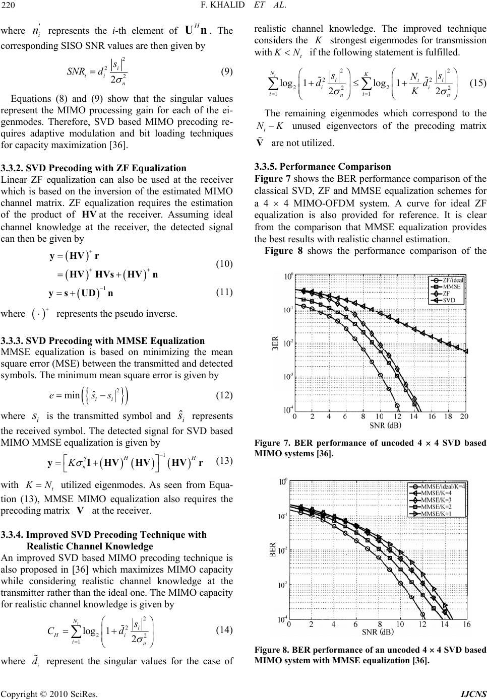 F. KHALID ET AL. 220 where represents the i-th element of ' i n H Un. The corresponding SISO SNR values are then given by 2 2 2 2 i ii n s SNR d (9) Copyright © 2010 SciRes. IJCNS Equations (8) and (9) show that the singular values represent the MIMO processing gain for each of the ei- genmodes. Therefore, SVD based MIMO precoding re- quires adaptive modulation and bit loading techniques for capacity maximization [36]. 3.3.2. SVD Precoding with ZF Equalization Linear ZF equalization can also be used at the receiver which is based on the inversion of the estimated MIMO channel matrix. ZF equalization requires the estimation of the product of at the receiver. Assuming ideal channel knowledge at the receiver, the detected signal can then be given b y HV yHVr HVHVsHV n (10) 1 ys UDn (11) where represents the pseudo inverse. 3.3.3. SVD Precoding with MMSE Equalization MMSE equalization is based on minimizing the mean square error (MSE) between the transmitted and detected symbols. The minimum mean square error is given by 2 ˆ min ii ess H (12) where is the transmitted symbol and represents the received symbol. The detected signal for SVD based MIMO MMSE equalization is given by i sˆi s 1 2H n K y IHV HVHVr (13) with t K N utilized eigenmodes. As seen from Equa- tion (13), MMSE MIMO equalization also requires the precoding matrix at the receiver. V 3.3.4. Improved SVD Precoding Technique with Realistic Channel Knowledge An improved SVD based MIMO precoding technique is also proposed in [36] which maximizes MIMO capacity while considering realistic channel knowledge at the transmitter rather than the ideal one. The MIMO capacity for realistic channel knowledge is given by 2 2 22 1 log 12 t Ni Hi in s Cd (14) where represent the singular values for the case of realistic channel knowledge. The improved technique considers the i d K strongest eigenmodes for transmission with t K N if the following statement is fulfilled. 22 22 22 22 11 log 1 t Nlog 1 22 K ii t ii ii nn ss N dd K (15) The remaining eigenmodes which correspond to the t NK unused eigenvectors of the precoding matrix are not utilized. V 3.3.5. Performance Comparison Figure 7 shows the BER performance comparison of the classical SVD, ZF and MMSE equalization schemes for a 4 4 MIMO-OFDM system. A curve for ideal ZF equalization is also provided for reference. It is clear from the comparison that MMSE equalization provides the best results with realistic channel estimation. Figure 8 shows the performance comparison of the Figure 7. BER performance of uncoded 4 4 SVD based MIMO systems [36]. Figure 8. BER performance of an uncoded 4 4 SVD based MIMO system with MMSE equalization [36]. 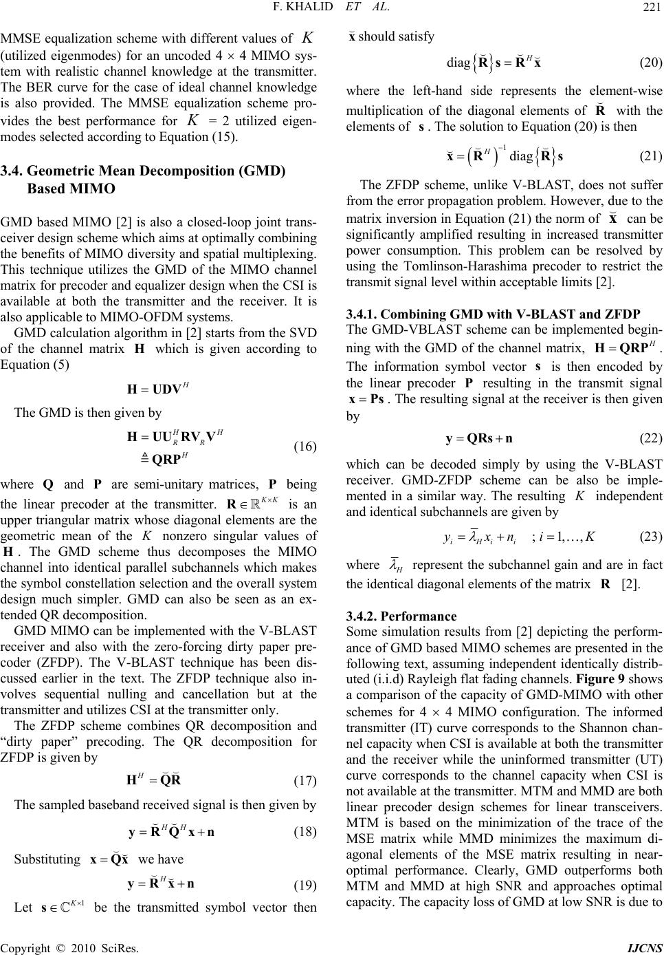 F. KHALID ET AL. 221 MMSE equalization scheme with different values of (utilized eigenmodes) for an uncoded 4 4 MIMO sys- tem with realistic channel knowledge at the transmitter. The BER curve for the case of ideal channel knowledge is also provided. The MMSE equalization scheme pro- vides the best performance for = 2 utilized eigen- modes selected according to Equation (15). K K 3.4. Geometric Mean Decomposition (GMD) Based MIMO GMD based MIMO [2] is also a closed-loop joint trans- ceiver design scheme which aims at optimally combining the benefits of MIMO diversity and spatial multiplexing. This technique utilizes the GMD of the MIMO channel matrix for precoder and equalizer design when the CSI is available at both the transmitter and the receiver. It is also applicable to MIMO-OFDM systems. GMD calculation algorithm in [2] starts from the SVD of the channel matrix which is given according to Equation (5) H H HUDV The GMD is then given by H H RR H HUURVV QRP (16) where and are semi-unitary matrices, P being the linear precoder at the transmitter. Q P K K R is an upper triangular matrix whose diagonal elements are the geometric mean of the K nonzero singular values of . The GMD scheme thus decomposes the MIMO channel into identical parallel subchannels which makes the symbol constellation selection and the overall system design much simpler. GMD can also be seen as an ex- tended QR decomposition. H GMD MIMO can be implemented with the V-BLAST receiver and also with the zero-forcing dirty paper pre- coder (ZFDP). The V-BLAST technique has been dis- cussed earlier in the text. The ZFDP technique also in- volves sequential nulling and cancellation but at the transmitter and utilizes CSI at the transmitter only. The ZFDP scheme combines QR decomposition and “dirty paper” precoding. The QR decomposition for ZFDP is given by HHQR (17) The sampled baseband received signal is then given by HH yRQxn (18) Substituting we have xQx H yRxn (19) Let be the transmitted symbol vector then should satisfy 1K s x diag H Rs Rx (20) where the left-hand side represents the element-wise multiplication of the diagonal elements of with the elements of . The solution to Equation (20) is then R s 1diag H xR Rs (21) The ZFDP scheme, unlike V-BLAST, does not suffer from the error propagation problem. However, due to the matrix inversion in Equation (21) the norm of can be significantly amplified resulting in increased transmitter power consumption. This problem can be resolved by using the Tomlinson-Harashima precoder to restrict the transmit signal level within acceptable limits [2]. x 3.4.1. Combining GMD with V-BLAST and ZFDP The GMD-VBLAST scheme can be implemented begin- ning with the GMD of the channel matrix, H HQRP. The information symbol vector is then encoded by the linear precoder resulting in the transmit signal s P xPs. The resulting signal at the receiver is then given by y QRsn (22) which can be decoded simply by using the V-BLAST receiver. GMD-ZFDP scheme can be also be imple- mented in a similar way. The resulting K independent and identical subchannels are given by ; 1,, iHii yxni K (23) where H represent the subchannel gain and are in fact the identical diagonal elements of the matrix [2]. R 3.4.2. Performance Some simulation results from [2] depicting the perform- ance of GMD based MIMO schemes are presented in the following text, assuming independent identically distrib- uted (i.i.d) Rayleigh flat fading channels. Figure 9 shows a comparison of the capacity of GMD-MIMO with oth er schemes for 4 4 MIMO configuration. The informed transmitter (IT) curve corresponds to the Shannon chan- nel capacity when CSI is available at both the transmitter and the receiver while the uninformed transmitter (UT) curve corresponds to the channel capacity when CSI is not available at the transmitter. MTM and MMD are both linear precoder design schemes for linear transceivers. MTM is based on the minimization of the trace of the MSE matrix while MMD minimizes the maximum di- agonal elements of the MSE matrix resulting in near- optimal performance. Clearly, GMD outperforms both MTM and MMD at high SNR and approaches optimal capacity. The capacity loss of GMD at low SNR is due to Co pyright © 2010 SciRes. IJCNS 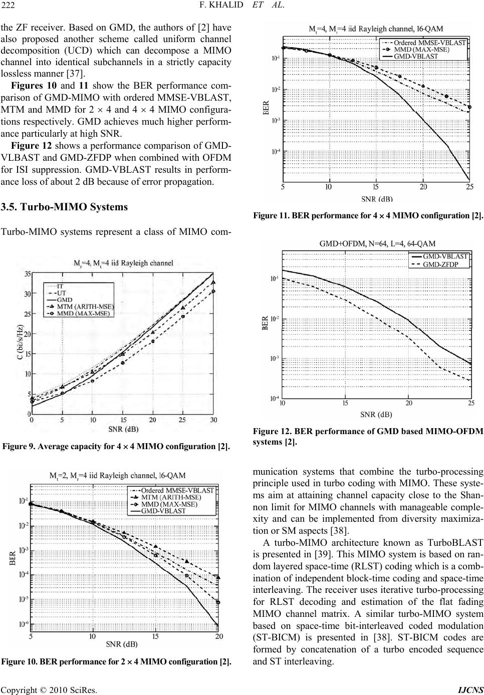 F. KHALID ET AL. 222 the ZF receiver. Based on GMD, the authors of [2] have also proposed another scheme called uniform channel decomposition (UCD) which can decompose a MIMO channel into identical subchannels in a strictly capacity lossless manner [37]. Figures 10 and 11 show the BER performance com- parison of GMD-MIMO with ordered MMSE-VBLAST, MTM and MMD for 2 4 and 4 4 MIMO configura- tions respectively. GMD achieves much higher perform- ance particularly at high SNR. Figure 12 shows a performance comparison of GMD- VLBAST and GMD-ZFDP when combined with OFDM for ISI suppression. GMD-VBLAST results in perform- ance loss of about 2 dB because of error propagation. 3.5. Turbo-MIMO Systems Turbo-MIMO systems represent a class of MIMO com- Figure 9. Average capacity for 4 4 MI MO configuration [2]. Figure 10. BER performan ce for 2 4 MI MO co nfigurat ion [2]. Figure 11. BER performan ce for 4 4 MI MO co nfigurat ion [2]. Figure 12. BER performance of GMD based MIMO-OFDM systems [2]. munication systems that combine the turbo-processing principle used in turbo coding with MIMO. These syste- ms aim at attaining channel capacity close to the Shan- non limit for MIMO channels with manageable comple- xity and can be implemented from diversity maximiza- tion or SM aspects [38]. A turbo-MIMO architecture known as TurboBLAST is presented in [39]. This MIMO system is based on ran- dom layered space-time (RLST) coding which is a comb- ination of independent block-time coding and space-time interleaving. The receiver uses iterative turbo-processing for RLST decoding and estimation of the flat fading MIMO channel matrix. A similar turbo-MIMO system based on space-time bit-interleaved coded modulation (ST-BICM) is presented in [38]. ST-BICM codes are formed by concatenation of a turbo encoded sequence and ST interleaving. Copyright © 2010 SciRes. IJCNS 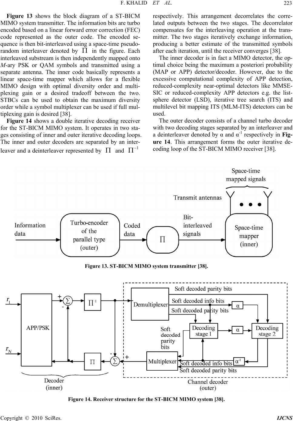 F. KHALID ET AL. Copyright © 2010 SciRes. IJCNS 223 Figure 13 shows the block diagram of a ST-BICM MIMO system transmitter. The information bits are turbo encoded based on a linear forward error correction (FEC) code represented as the outer code. The encoded se- quence is then bit-interleaved using a space-time pseudo- random interleaver denoted by in the figure. Each interleaved substream is then independently mapped onto M-ary PSK or QAM symbols and transmitted using a separate antenna. The inner code basically represents a linear space-time mapper which allows for a flexible MIMO design with optimal diversity order and multi- plexing gain or a desired tradeoff between the two. STBCs can be used to obtain the maximum diversity order while a symbol multiplexer can be used if full mul- tiplexing gain is desired [38]. Figure 14 shows a double iterative decoding receiver for the ST-BICM MIMO system. It operates in two sta- ges consisting of inner and outer iterative decoding loops. The inner and outer decoders are separated by an inter- leaver and a deinterleaver represented by and 1 respectively. This arrangement decorrelates the corre- lated outputs between the two stages. The decorrelator compensates for the interleaving operation at the trans- mitter. The two stages iteratively exchange information, producing a better estimate of the transmitted symbols after each iteration, until the receiver converges [38]. The inner decoder is in fact a MIMO detector, the op- timal choice being the maximum a posteriori probability (MAP or APP) detector/decoder. However, due to the excessive computational complexity of APP detection, reduced-complexity near-optimal detectors like MMSE- SIC or reduced-complexity APP detectors e.g. the list- sphere detector (LSD), iterative tree search (ITS) and multilevel bit mapping ITS (MLM-ITS) detectors can be used. The outer decoder consists of a channel turbo decoder with two decoding stages separated by an interleaver and a deinterleaver denoted by α and α-1 respectively in Fig- ure 14. This arrangement forms the outer iterative de- coding loop of the ST-BICM MIMO receiver [38]. Figure 13. ST-BICM MIMO system transmitter [38]. Figure 14. Receiver structure for the ST-BICM MIMO system [38]. 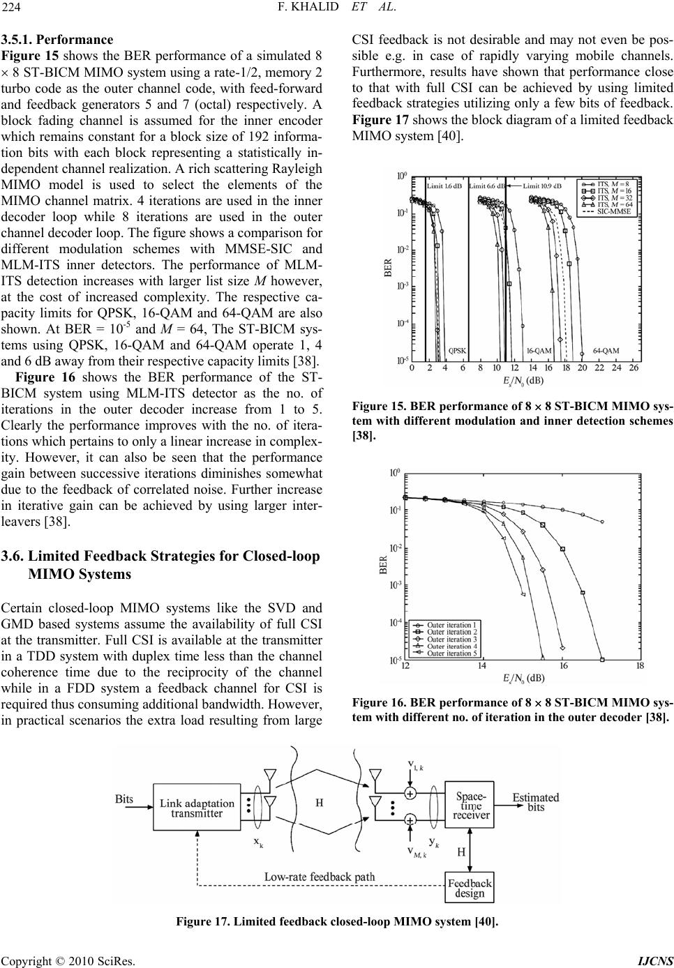 F. KHALID ET AL. 224 3.5.1. Performance Figure 15 shows the BER performance of a simulated 8 8 ST-BICM MIMO system using a rate-1/2, memory 2 turbo code as the outer channel code, with feed-forward and feedback generators 5 and 7 (octal) respectively. A block fading channel is assumed for the inner encoder which remains constant for a block size of 192 informa- tion bits with each block representing a statistically in- dependent channel realization. A rich scattering Rayleigh MIMO model is used to select the elements of the MIMO channel matrix. 4 iterations are used in the inner decoder loop while 8 iterations are used in the outer channel decoder loop. The figure shows a comparison for different modulation schemes with MMSE-SIC and MLM-ITS inner detectors. The performance of MLM- ITS detection increases with larger list size M however, at the cost of increased complexity. The respective ca- pacity limits for QPSK, 16-QAM and 64-QAM are also shown. At BER = 10-5 and M = 64, The ST-BICM sys- tems using QPSK, 16-QAM and 64-QAM operate 1, 4 and 6 dB away from their respective capacity limits [38]. Figure 16 shows the BER performance of the ST- BICM system using MLM-ITS detector as the no. of iterations in the outer decoder increase from 1 to 5. Clearly the performance improves with the no. of itera- tions which pertains to only a linear increase in complex- ity. However, it can also be seen that the performance gain between successive iterations diminishes somewhat due to the feedback of correlated noise. Further increase in iterative gain can be achieved by using larger inter- leavers [38]. 3.6. Limited Feedback Strategies for Closed-loop MIMO Systems Certain closed-loop MIMO systems like the SVD and GMD based systems assume the availability of full CSI at the transmitter. Full CSI is available at the transmitter in a TDD system with duplex time less than the channel coherence time due to the reciprocity of the channel while in a FDD system a feedback channel for CSI is required thus consuming additional bandwidth. However, in practical scenarios the extra load resulting from large CSI feedback is not desirable and may not even be pos- sible e.g. in case of rapidly varying mobile channels. Furthermore, results have shown that performance close to that with full CSI can be achieved by using limited feedback strategies utilizing only a few bits of feedback. Figure 17 shows the block diagram of a limited feedback MIMO system [40]. Figure 15. BER performance of 8 8 ST-BICM MIMO sys- tem with different modulation and inner detection schemes [38]. Figure 16. BER performance of 8 8 ST-BICM MIMO sys- tem with different no. of iteration in the outer decoder [38]. Figure 17. Limited feedback closed-loop MIMO system [40]. Copyright © 2010 SciRes. IJCNS 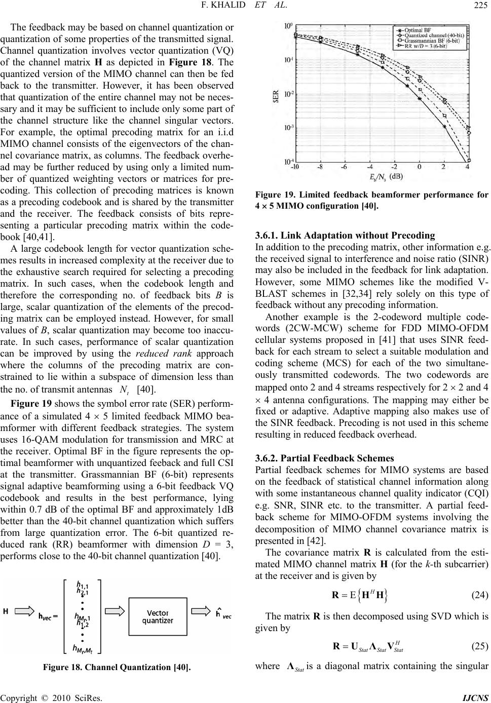 F. KHALID ET AL. 225 The feedback may be based on channel quantization or quantization of some properties of the transmitted signal. Channel quantization involves vector quantization (VQ) of the channel matrix H as depicted in Figure 18. The quantized version of the MIMO channel can then be fed back to the transmitter. However, it has been observed that quantization of the entire channel may not be neces- sary and it may be sufficient to include only some part of the channel structure like the channel singular vectors. For example, the optimal precoding matrix for an i.i.d MIMO channel consists of the eigenvectors of the chan- nel covariance matrix, as columns. The feedback overhe- ad may be further reduced by using only a limited num- ber of quantized weighting vectors or matrices for pre- coding. This collection of precoding matrices is known as a precoding codebook and is shared by the transmitter and the receiver. The feedback consists of bits repre- senting a particular precoding matrix within the code- book [40,41]. A large codebook length for vector quantization sche- mes results in increased complexity at the receiver due to the exhaustive search required for selecting a precoding matrix. In such cases, when the codebook length and therefore the corresponding no. of feedback bits B is large, scalar quantization of the elements of the precod- ing matrix can be employed instead. However, for small values of B, scalar quantization may become too inaccu- rate. In such cases, performance of scalar quantization can be improved by using the reduced rank approach where the columns of the precoding matrix are con- strained to lie within a subspace of dimension less than the no. of transmit antennas [40]. t N Figure 19 shows the symbol error rate (SER) perform- ance of a simulated 4 5 limited feedback MIMO bea- mformer with different feedback strategies. The system uses 16-QAM modulation for transmission and MRC at the receiver. Optimal BF in the figure represents the op- timal beamformer with unquantized feeback and full CSI at the transmitter. Grassmannian BF (6-bit) represents signal adaptive beamforming using a 6-bit feedback VQ codebook and results in the best performance, lying within 0.7 dB of the optimal BF and approximately 1dB better than the 40-bit channel quantization which suffers from large quantization error. The 6-bit quantized re- duced rank (RR) beamformer with dimension D = 3, performs close to the 40-bit channel quantization [40]. Figure 18. Channel Quantization [40]. Figure 19. Limited feedback beamformer performance for 4 5 MIMO configuration [40]. 3.6.1. Link Adaptation without Precoding In addition to the precoding matrix, other information e.g. the received signal to interference and noise ratio (SINR) may also be included in the feedback for link adaptation. However, some MIMO schemes like the modified V- BLAST schemes in [32,34] rely solely on this type of feedback without any precoding information. Another example is the 2-codeword multiple code- words (2CW-MCW) scheme for FDD MIMO-OFDM cellular systems proposed in [41] that uses SINR feed- back for each stream to select a suitable modulation and coding scheme (MCS) for each of the two simultane- ously transmitted codewords. The two codewords are mapped onto 2 and 4 streams respectively for 2 2 and 4 4 antenna configurations. The mapping may either be fixed or adaptive. Adaptive mapping also makes use of the SINR feedback. Precoding is not used in this scheme resulting in reduced feedback overhead. 3.6.2. Partial Feedback Schemes Partial feedback schemes for MIMO systems are based on the feedback of statistical channel information along with some instantaneous channel quality indicator (CQI) e.g. SNR, SINR etc. to the transmitter. A partial feed- back scheme for MIMO-OFDM systems involving the decomposition of MIMO channel covariance matrix is presented in [42]. The covariance matrix R is calculated from the esti- mated MIMO channel matrix H (for the k-th subcarrier) at the receiver and is given by EH RHH (24) The matrix R is then decomposed using SVD which is given by H StatStat Stat RUΛV (25) where is a diagonal matrix containing the singular Stat Λ Co pyright © 2010 SciRes. IJCNS  F. KHALID ET AL. 226 values while and are unitary matrices. The feedback includes the matrix and the column vectors of for power allocation and spatial proc- essing (precoding) at the transmitter [42]. Stat U Stat Stat V Stat Λ V Figure 20 shows the block diagram of a TR NN MIMO-OFDM system based on this partial feedback scheme which transmits spatial streams using OFDM subcarriers. The received signal vector for the k-th subcarrier is given by S N HQAx T N C N y = (26) where x is the transmit data vector, H is the MIMO channel matrix for the k-th subcarrier, A is a diagonal matrix with diagonal elements determined by the matrix feedback for power allocation to the active spatial streams, and the S N St Λat S N matrix Q represents a spatial processing transformation which maps the spatial streams to the transmit antennas. The Q matrix is con- structed from the vectors of received at the trans- mitter via feedback and is used to maximize the received energy for each transmitted spatial stream. This enables Stat V maximum ratio transmission (MRT) and SVD beam- forming along with tracking of spatial variations of the MIMO channel [42]. The MIMO channel covariance and the corresponding channel singular values do not vary rapidly with time even at vehicular speeds around 100 km/h [42]. This greatly reduces the feedback load on the system and makes this closed-loop MIMO-OFDM system suitable for mobile environments. Figures 21 and 22 show the simulated frame error rate (FER) performance of the proposed MIMO-OFDM sys- tem in comparison with open-loop SM and perfect CSI feedback MIMO-OFDM systems, for 2 2 and 4 4 MIMO configurations respectively. The figures include FER performance curves for QPSK and 64-QAM modu- lation in a low speed mobile scenario using the ITU PB channel profile with vehicular speeds of 3 km/h. The OFDM scheme is based on 512-point FFT with 15 sub- channels for data transmission each consisting of 20 con- tinuous subcarriers, for a total bandwidth of 5 MHz. The frame duration is about 0.5ms. Turbo coding is employed for FEC and MMSE detection is used at the receiver. Figure 20. MIMO-OFDM system with partial feedback [42]. Figure 21. FER performance for coded 2 2 MIMO con- figuration [42]. Figure 22. FER performance for coded 4 4 MIMO con- figuration [42]. Copyright © 2010 SciRes. IJCNS 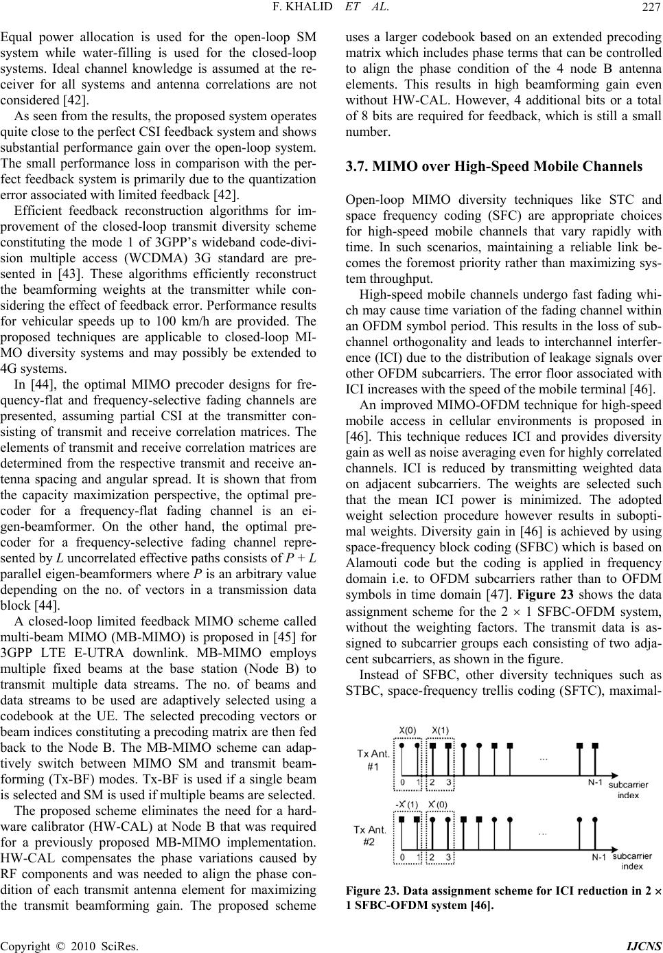 F. KHALID ET AL. 227 Equal power allocation is used for the open-loop SM system while water-filling is used for the closed-loop systems. Ideal channel knowledge is assumed at the re- ceiver for all systems and antenna correlations are not considered [42]. As seen from the results, the proposed system operates quite close to the perfect CSI feedback system and shows substantial performance gain over the open-loop system. The small performance loss in comparison with the per- fect feedback system is primarily due to the quantization error associated with limited feedback [42]. Efficient feedback reconstruction algorithms for im- provement of the closed-loop transmit diversity scheme constituting the mode 1 of 3GPP’s wideband code-divi- sion multiple access (WCDMA) 3G standard are pre- sented in [43]. These algorithms efficiently reconstruct the beamforming weights at the transmitter while con- sidering the effect of feedback error. Performance results for vehicular speeds up to 100 km/h are provided. The proposed techniques are applicable to closed-loop MI- MO diversity systems and may possibly be extended to 4G systems. In [44], the optimal MIMO precoder designs for fre- quency-flat and frequency-selective fading channels are presented, assuming partial CSI at the transmitter con- sisting of transmit and receive correlation matrices. The elements of transmit and receive correlation matrices are determined from the respective transmit and receive an- tenna spacing and angular spread. It is shown that from the capacity maximization perspective, the optimal pre- coder for a frequency-flat fading channel is an ei- gen-beamformer. On the other hand, the optimal pre- coder for a frequency-selective fading channel repre- sented by L uncorrelated effective paths consists of P + L parallel eigen-beamformers where P is an arbitrary value depending on the no. of vectors in a transmission data block [44]. A closed-loop limited feedback MIMO scheme called multi-beam MIMO (MB-MIMO) is proposed in [45] for 3GPP LTE E-UTRA downlink. MB-MIMO employs multiple fixed beams at the base station (Node B) to transmit multiple data streams. The no. of beams and data streams to be used are adaptively selected using a codebook at the UE. The selected precoding vectors or beam indices constituting a precoding matrix are then fed back to the Node B. The MB-MIMO scheme can adap- tively switch between MIMO SM and transmit beam- forming (Tx-BF) modes. Tx-BF is used if a single beam is selected and SM is used if multiple beams are selected. The proposed scheme eliminates the need for a hard- ware calibrator (HW-CAL) at Node B that was required for a previously proposed MB-MIMO implementation. HW-CAL compensates the phase variations caused by RF components and was needed to align the phase con- dition of each transmit antenna element for maximizing the transmit beamforming gain. The proposed scheme uses a larger codebook based on an extended precoding matrix which includes phase terms that can be controlled to align the phase condition of the 4 node B antenna elements. This results in high beamforming gain even without HW-CAL. However, 4 additional bits or a total of 8 bits are required for feedback, which is still a small number. 3.7. MIMO over High-Speed Mobile Channels Open-loop MIMO diversity techniques like STC and space frequency coding (SFC) are appropriate choices for high-speed mobile channels that vary rapidly with time. In such scenarios, maintaining a reliable link be- comes the foremost priority rather than maximizing sys- tem throughput. High-speed mobile channels undergo fast fading whi- ch may cause time variation of the fading channel within an OFDM symbol period. This results in the loss of sub- channel orthogonality and leads to interchannel interfer- ence (ICI) due to the distribution of leakage signals over other OFDM subcarriers. The error floor associated with ICI increases with the speed of the mobile terminal [46]. An improved MIMO-OFDM technique for high-speed mobile access in cellular environments is proposed in [46]. This technique reduces ICI and provides diversity gain as well as noise averaging even for highly correlated channels. ICI is reduced by transmitting weighted data on adjacent subcarriers. The weights are selected such that the mean ICI power is minimized. The adopted weight selection procedure however results in subopti- mal weights. Diversity gain in [46] is achieved by using space-frequency block coding (SFBC) which is based on Alamouti code but the coding is applied in frequency domain i.e. to OFDM subcarriers rather than to OFDM symbols in time domain [47]. Figure 23 shows the data assignment scheme for the 2 1 SFBC-OFDM system, without the weighting factors. The transmit data is as- signed to subcarrier groups each consisting of two adja- cent subcarriers, as shown in the figure. Instead of SFBC, other diversity techniques such as STBC, space-frequency trellis coding (SFTC), maximal- Figure 23. Data assignment scheme for ICI reduction in 2 1 SFBC-OFDM system [46]. C opyright © 2010 SciRes. IJCNS 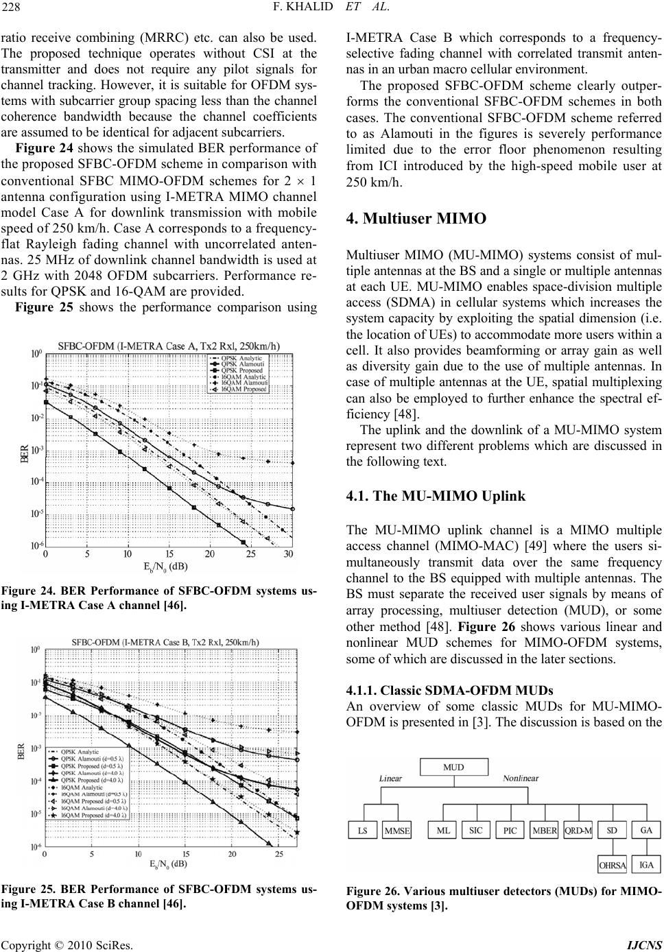 F. KHALID ET AL. 228 ratio receive combining (MRRC) etc. can also be used. The proposed technique operates without CSI at the transmitter and does not require any pilot signals for channel tracking. However, it is suitable for OFDM sys- tems with subcarrier group spacing less than the channel coherence bandwidth because the channel coefficients are assumed to be identical for adjacent subcarriers. Figure 24 shows the simulated BER performance of the proposed SFBC-OFDM scheme in comparison with conventional SFBC MIMO-OFDM schemes for 2 1 antenna configuration using I-METRA MIMO channel model Case A for downlink transmission with mobile speed of 250 km/h. Case A corresponds to a frequency- flat Rayleigh fading channel with uncorrelated anten- nas. 25 MHz of downlink channel bandwidth is used at 2 GHz with 2048 OFDM subcarriers. Performance re- sults for QPSK and 16-QAM are provided. Figure 25 shows the performance comparison using Figure 24. BER Performance of SFBC-OFDM systems us- ing I-METRA Case A channel [46]. Figure 25. BER Performance of SFBC-OFDM systems us- ing I-METRA Case B channel [46]. I-METRA Case B which corresponds to a frequency- selective fading channel with correlated transmit anten- nas in an urban macro cellular environment. The proposed SFBC-OFDM scheme clearly outper- forms the conventional SFBC-OFDM schemes in both cases. The conventional SFBC-OFDM scheme referred to as Alamouti in the figures is severely performance limited due to the error floor phenomenon resulting from ICI introduced by the high-speed mobile user at 250 km/h. 4. Multiuser MIMO Multiuser MIMO (MU-MIMO) systems consist of mul- tiple antennas at the BS and a single or multiple antennas at each UE. MU-MIMO enables space-division multiple access (SDMA) in cellular systems which increases the system capacity by exploiting the spatial dimension (i.e. the location of UEs) to accommodate more users within a cell. It also provides beamforming or array gain as well as diversity gain due to the use of multiple antennas. In case of multiple antennas at the UE, spatial multiplexing can also be employed to further enhance the spectral ef- ficiency [48]. The uplink and the downlink of a MU-MIMO system represent two different problems which are discussed in the following text. 4.1. The MU-MIMO Uplink The MU-MIMO uplink channel is a MIMO multiple access channel (MIMO-MAC) [49] where the users si- multaneously transmit data over the same frequency channel to the BS equipped with multiple antennas. The BS must separate the received user signals by means of array processing, multiuser detection (MUD), or some other method [48]. Figure 26 shows various linear and nonlinear MUD schemes for MIMO-OFDM systems, some of which are discussed in the later sections. 4.1.1. Classic SDM A -OF DM MUDs An overview of some classic MUDs for MU-MIMO- OFDM is presented in [3]. The discussion is based on the Figure 26. Various multiuser detectors (MUDs) for MIMO- OFD M sys tems [3]. Copyright © 2010 SciRes. IJCNS 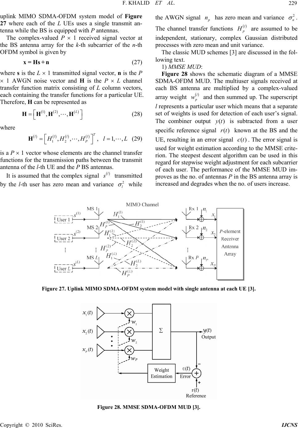 F. KHALID ET AL. Copyright © 2010 SciRes. IJCNS 229 uplink MIMO SDMA-OFDM system model of Figure 27 where each of the L UEs uses a single transmit an- tenna while the BS is equipped with P antennas. the AWGN signal has zero mean and variance p n2 n . The channel transfer functions l p H are assumed to be independent, stationary, complex Gaussian distributed processes with zero mean and unit variance. The complex-valued P 1 received signal vector at the BS antenna array for the k-th subcarrier of the n-th OFDM symbol is given by The classic MUD schemes [3] are discussed in the fol- lowing text. x=Hs+n (27) 1) MMSE MUD: where s is the L 1 transmitted signal vector, n is the P 1 AWGN noise vector and H is the P L channel transfer function matrix consisting of L column vectors, each containing the transfer functions for a particular UE. Therefore, H ca n be represe nted as 12 ,,, L HHH H (28) where 12 ,,,, 1,, T llll P H HH l HL (29) Figure 28 shows the schematic diagram of a MMSE SDMA-OFDM MUD. The multiuser signals received at each BS antenna are multiplied by a complex-valued array weight l p w and then summed up . The superscript l represents a particular user which means that a separate set of weights is used for detection of each user’s signal. The combiner output is subtracted from a user specific reference signal known at the BS and the UE, resulting in an error signal . The error signal is used for weight estimation according to the MMSE crite- rion. The steepest descent algorithm can be used in this regard for stepwise weight adjustment for each subcarrier of each user. The performance of the MMSE MUD im- proves as the no. of antenn as P in the BS antenna array is increased and degrades when the no. of users increase. ()yt ()rt ()єt is a P 1 vector whose eleme nts are the cha nnel tran sfer functions for the transmission paths between the transmit antenna of the l-th UE and the P BS antennas. It is assumed that the complex signal l s transmitted by the l-th user has zero mean and variance 2 l while Figure 27. Uplink MIMO SDMA-OFDM system model with single antenna at each UE [3]. Figure 28. MMSE SDMA-OFDM MUD [3]. 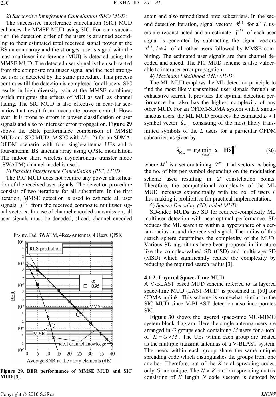 F. KHALID ET AL. 230 2) Successive Interference Cancellation (SIC) MUD: The successive interference cancellation (SIC) MUD enhances the MMSE MUD using SIC. For each subcar- rier, the detection order of the users is arranged accord- ing to their estimated total received signal power at the BS antenna array and the strongest user’s signal with the least multiuser interference (MUI) is detected using the MMSE MUD. The detected user signal is then subtracted from the composite multiuser signal and the next strong- est user is detected by the same procedure. This process continues till the detection is completed for all users. SIC results in high diversity gain at the MMSE combiner, which mitigates the effects of MUI as well as channel fading. The SIC MUD is also effective in near-far sce- narios that result from inaccurate power control. How- ever, it is prone to errors in power classification of user signals and also to interuser error propagation. Figure 29 shows the BER performance comparison of MMSE MUD and SIC MUD (M-SIC with M = 2) for an SDMA- OFDM scenario with four single-antenna UEs and a four-antenna BS antenna array using QPSK modulation. The indoor short wireless asynchronous transfer mode (SWATM) channel model is used. Copyright © 2010 SciRes. IJCNS 3) Parallel Interference Cancellation (PIC) MUD: The PIC MUD does not require any power classifica- tion of the received user signals. The detection procedure consists of two iterations for all subcarriers. In the first iteration, MMSE detection is used to estimate all user signals l y from the received composite multiuser sig- nal vector x. In case of channel encoded transmission, all user signals must be decoded, sliced, channel encoded Figure 29. BER performance of MMSE MUD and SIC MUD [3]. again and also remodulated onto subcarriers. In the sec- ond detection iteration, signal vectors for all L us- ers are reconstructed and an estimate l x k y of each user signal is generated by subtracting the signal vectors , llk x of all other users followed by MMSE com- bining. The estimated user signals are then channel de- coded and sliced. The PIC MUD scheme is also vulner- able to interuser error propagation. 4) Maximum Likelihood (ML) MUD: The ML MUD employs the ML detection principle to find the most likely transmitted user signals through an exhaustive search. It provides the optimal detection per- formance but also has the highest complexity of any other MUD. For an OFDM-SDMA system with L simul- taneous users, the ML MUD produces the estimated L 1 symbol vector consisting of the most likely trans- mitted symbols of the L users for a particular OFDM subcarrier, as given by ML ˆ s 2 ML ˆarg min L s sx M Hs (30) where M L is a set containing trial vectors, m being the no. of bits per symbol depending on the modulation scheme used resulting in constellation points. Therefore, the computational complexity of the ML MUD increases exponentially with the no. of users L thus making it prohibitive for practical implementation. 2mL 2m 5) Sphere Decoding (SD) aided MUD: SD-aided MUDs use SD for reduced-complexity ML multiuser detection with near-optimal performance. SD reduces the ML search to within a hypersphere of a cer- tain radius around the received signal. The radius of this search sphere determines the complexity of the MUD. Various SD algorithms have been proposed in literature like the complex-valued SD (CSD) and multistage SD (MSD) which significantly reduce the complexity by reducing the required search radius [3]. 4.1.2. Layered Space-Time MUD A V-BLAST based MUD scheme referred to as layered space-time MUD (LAST-MUD) is presented in [50] for CDMA uplink. This scheme is somewhat similar to the SIC MUD since V-BLAST detection also incorporates SIC. Figure 30 shows the layered space-time MU-MIMO system block diagram. Here the single antenna users are arranged in G groups each containing M users for a total of K GM . The UEs within each group are treated as the multiple transmit antennas of a V-BLAST system. The users within each group share the same unique spreading code which distinguishes the groups from one another. Therefore, out of the K total spreading codes, only G are unique. The N K random spreading matrix consisting of K length N code vectors is denoted by 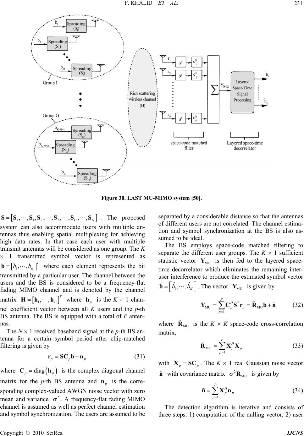 F. KHALID ET AL. 231 Figure 30. LAST MU-MIMO system [50]. 112 2 ,,,,,,,,, G SSSSSSS 1,, T K bbb 1,,T P Hhh G . The proposed system can also accommodate users with multiple an- tennas thus enabling spatial multiplexing for achieving high data rates. In that case each user with multiple transmit antennas will be considered as one group. The K 1 transmitted symbol vector is represented as where each element represents the bit transmitted by a particular user. The channel between the users and the BS is considered to be a frequency-flat fading MIMO channel and is denoted by the channel matrix where p h is the K 1 chan- nel coefficient vector between all K users and the p-th BS antenna. The BS is equipped with a total of P anten- nas. Co pyright © 2010 SciRes. IJCNS The N 1 received baseband signal at the p-th BS an- tenna for a certain symbol period after chip-matched filtering is given by pp rSCbn p p h (31) where is the complex diagonal channel matrix for the p-th BS antenna and diag p C p n is the corre- sponding co mplex-valued AWGN noise vector with zero mean and variance 2 . A frequency-flat fading MIMO channel is assumed as well as perfect channel estimation and symbol synchronization. The users are assumed to be separated by a considerable distance so that the antennas of different users are not correlated. The channel estima- tion and symbol synchronization at the BS is also as- sumed to be ideal. The BS employs space-code matched filtering to separate the different user groups. The K 1 sufficient statistic vector is then fed to the layered space- time decorrelator which eliminates the remaining inter- user interference to produce the estimated symbol vector MU Y 1 ˆˆ ˆ,, K bb b. The vector is given by MU Y MU MU 1 PHT pp p YCSrRb n (32) where is the K K space-code cross-correlation matrix, MU R MU 1 PH p p p RX X (33) with p p XSC. The K 1 real Gaussian noise vector with covariance matrix is given by n 2MU R 1 PH p p p nXn (34) The detection algorithm is iterative and consists of three steps: 1) computation of the nulling vector, 2) user 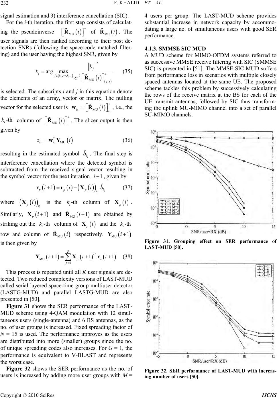 F. KHALID ET AL. 232 signal estimation and 3) interference cancellation (SIC). For the i-th iteration, the first step consists of calculat- ing the pseudoinverse of MU i R MU iR . The user signals are then ranked according to their post de- tection SNRs (following the space-code matched filter- ing) and the user having the highest SNR, given by 11 2 ,, 2MU , arg max i j ijk k j j b ki R (35) is selected. The subscripts i and j in this equation denote the elements of an array, vector or matrix. The nulling vector for the selected user is , i.e., the column of . The slicer output is then given by MU ii kk i wR i -th i k MU i R MU ii T kk zwY (36) resulting in the estimated symbol . The final step is interference cancellation where the detected symbol is subtracted from the received signal vector resulting in the symbol vector for the next iteration , given by ˆi k b 1i ˆ 1i i p pp k iii rrX k b (37) where is the column of i pk iX-th i k piX -th i k . Similarly, and are obtained by striking ou t the column of and the row and column of respectively. piX i k 1 -th 1 p X MU iR i i MU R MU 1i Y is then given by MU 1 11 PH pp p ii YXr 1i (38) This process is repeated until all K user signals are de- tected. Two reduced complexity versions of LAST-MUD called serial layered space-time group multiuser detector (LASTG-MUD) and parallel LASTG-MUD are also presented in [50]. Figure 31 shows the SER performance of the LAST- MUD scheme using 4-QAM modulation with 12 simul- taneous users (single-antenna) and 6 BS antennas, as the no. of user groups is increased. Fixed spreading factor of N = 15 is used. The performance improves as the users are distributed into more (smaller) groups since the no. of unique spreading codes also increases. For G = 1, the performance is equivalent to V-BLAST and represents the worst case. Figure 32 shows the SER performance as the no. of users is increased by adding more user groups with M = 4 users per group. The LAST-MUD scheme provides substantial increase in network capacity by accommo- dating a large no. of simultaneous users with good SER performance. 4.1.3. SMMSE SIC MUD A MUD scheme for MIMO-OFDM systems referred to as successive MMSE receive filtering with SIC (SMMSE SIC) is presented in [51]. The MMSE SIC MUD suffers from performance loss in scenarios with multiple closely spaced antennas located at the same UE. The proposed scheme tackles this problem by successively calculating the rows of the receive matrix at the BS for each of the UE transmit antennas, followed by SIC thus transform- ing the uplink MU-MIMO channel into a set of parallel SU-MIMO channels. Figure 31. Grouping effect on SER performance of LAST-MUD [50]. Figure 32. SER performance of LAST-MUD with increas- ing number of users [50]. Copyright © 2010 SciRes. IJCNS 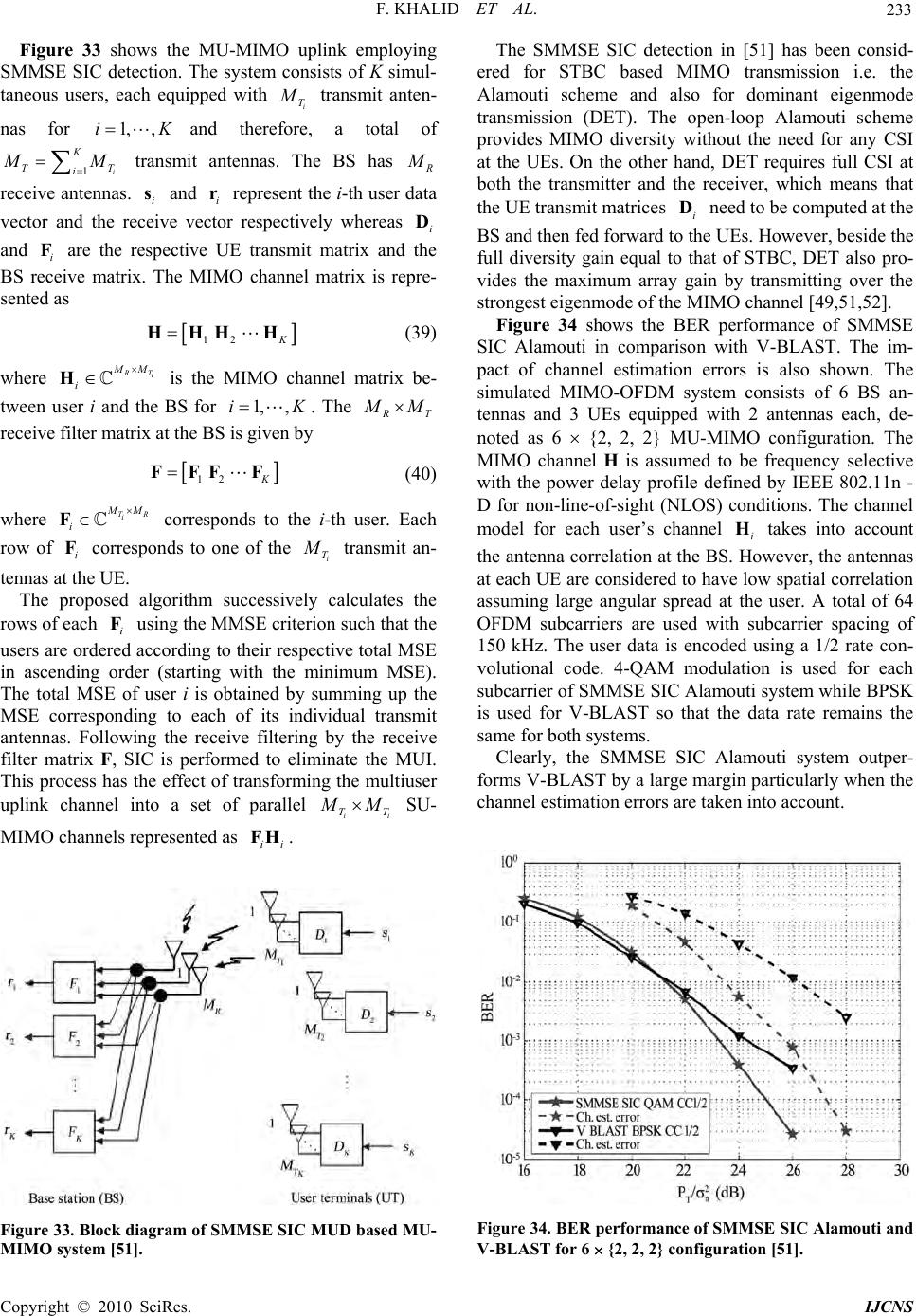 F. KHALID ET AL. 233 Figure 33 shows the MU-MIMO uplink employing SMMSE SIC detection. The system consists of K simul- taneous users, each equipped with i T M transmit anten- nas for and therefore, a total of 1, ,i i T K 1 K T i M M transmit antennas. The BS has R M receive antennas. and represent the i-th user data vector and the receive vector respectively whereas and are the respective UE transmit matrix and the BS receive matrix. The MIMO channel matrix is repre- sented as i si r i D i F 12 K HHH H (39) where R Ti MM i H is the MIMO channel matrix be- tween user i and the BS for 1, ,iK . The R T M M receive filter matrix at the BS is given by 12 K FFFF (40) where TR i M M i F i F corresponds to the i-th user. Each row of corresponds to one of the i T M transmit an- tennas at the UE. The proposed algorithm successively calculates the rows of each using the MMSE criterion such that the users are ordered according to their respective total MSE in ascending order (starting with the minimum MSE). The total MSE of user i is obtained by summing up the MSE corresponding to each of its individual transmit antennas. Following the receive filtering by the receive filter matrix F, SIC is performed to eliminate the MUI. This process has the effect of transforming the multiuser uplink channel into a set of parallel i F i Ti T M M SU- MIMO channels represented as . ii FH Figure 33. Block diagram of SMMSE SIC MUD based MU- MIMO system [51]. The SMMSE SIC detection in [51] has been consid- ered for STBC based MIMO transmission i.e. the Alamouti scheme and also for dominant eigenmode transmission (DET). The open-loop Alamouti scheme provides MIMO diversity without the need for any CSI at the UEs. On the other hand, DET requires full CSI at both the transmitter and the receiver, which means that the UE transmit matrices need to be computed at the BS and then fed forward to the UEs. However, beside the full diversity gain equal to that of STBC, DET also pro- vides the maximum array gain by transmitting over the strongest eigenmode of the MIMO channel [49,51,52]. i D Figure 34 shows the BER performance of SMMSE SIC Alamouti in comparison with V-BLAST. The im- pact of channel estimation errors is also shown. The simulated MIMO-OFDM system consists of 6 BS an- tennas and 3 UEs equipped with 2 antennas each, de- noted as 6 {2, 2, 2} MU-MIMO configuration. The MIMO channel H is assumed to be frequency selective with the power delay profile defined by IEEE 802.11n - D for non-line-of-sight (NLOS) conditions. The channel model for each user’s channel takes into account the antenna correlation at the BS. However, the antennas at each UE are considered to have low spatial correlation assuming large angular spread at the user. A total of 64 OFDM subcarriers are used with subcarrier spacing of 150 kHz. The user data is encoded using a 1/2 rate con- volutional code. 4-QAM modulation is used for each subcarrier of SMMSE SIC Alamouti system while BPSK is used for V-BLAST so that the data rate remains the same for both systems. i H Clearly, the SMMSE SIC Alamouti system outper- forms V-BLAST by a large margin particularly when the channel estimation errors are taken into account. Figure 34. BER performance of SMMSE SIC Alamouti and V-BLAST for 6 {2, 2, 2} configuration [51]. Co pyright © 2010 SciRes. IJCNS 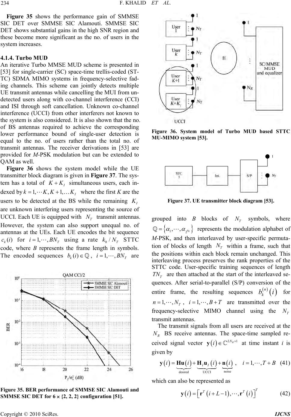 F. KHALID ET AL. 234 Figure 35 shows the performance gain of SMMSE SIC DET over SMMSE SIC Alamouti. SMMSE SIC DET shows substantial gains in the high SNR region and these become more significant as the no. of users in the system increases. 4.1.4. Turbo MUD An iterative Turbo MMSE MUD scheme is presented in [53] for single-carrier (SC) space-time trellis-coded (ST- TC) SDMA MIMO systems in frequency-selective fad- ing channels. This scheme can jointly detects multiple UE transmit antennas while cancelling the MUI from un- detected users along with co-channel interference (CCI) and ISI through soft cancellation. Unknown co-channel interference (UCCI) from other interferers not known to the system is also considered. It is also shown that the no. of BS antennas required to achieve the corresponding lower performance bound of single-user detection is equal to the no. of users rather than the total no. of transmit antennas. The receiver derivations in [53] are provided for M-PSK modulation but can be extended to QAM as well. Figure 36 shows the system model while the UE transmitter block diagram is given in Figure 37. The sys- tem has a total of I K K , 1, simultaneous users, each in- dexed by1, I kKKK where the first K are the users to be detected at the BS while the remaining I K are unknown interfering users representing the source of UCCI. Each UE is equipped with transmit antennas. However, the system can also support unequal no. of antennas at the UEs. Each UE encodes the bit sequence for using a rate STTC code, where B represents the frame length in symbols. The encoded sequences , are T N () k ci 1,i () k bi ,T BN 0/T kN 1, ,iT BN Figure 35. BER performance of SMMSE SIC Alamouti and SMMSE SIC DET for 6 {2, 2, 2} configuration [51]. Figure 36. System model of Turbo MUD based STTC MU- MIMO syst em [53]. Figure 37. UE transmitter block diagram [53]. grouped into B blocks of symbols, where T N 0 12 ,,k T TN represents the modulation alphabet of M-PSK, and then interleaved by user-specific permuta- tion of blocks of length within a frame, such that the positions within each block remain unchanged. This interleaving process preserves the rank properties of the STTC code. User-specific training sequences of length are then attached at the start of the interleaved se- quences. After serial-to-parallel (S/P) conversion of the entire frame, the resulting sequences T N n k bi for 1,, T nN , 1, ,iBT are transmitted over the frequency-selective MIMO channel using the transmit antennas. T N The transmit signals from all users are received at the R N BS receive antennas. The space-time sampled re- ceived signal vector 1 R LN i y at time instant i is given by noise desired UCCI , 1,, II ii iiiTB yHuHu n T (41) which can also be represented as 1, ,T T iiL i yr r (42) Copyright © 2010 SciRes. IJCNS 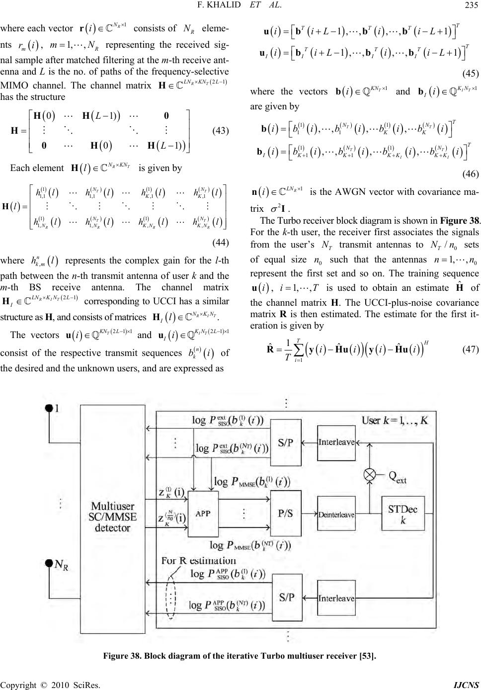 F. KHALID ET AL. Copyright © 2010 SciRes. IJCNS 235 where each vector 1 R N i r consists of R N eleme- nts , m ri 1, , R mN representing the received sig- nal sample after matched filtering at the m-th receive ant- enna and L is the no. of paths of the frequency-selective MIMO channel. The channel matrix 21 RT KN LLN H has the structure 1, ,, ,1 1, ,, ,1 T TTT T TTT IIII iiLi iL iiLi iL ubb b ubbb (45) 01) 01 L L HH 0 H 0H H where the vectors 1 T KN i b and 1 IT KN Ii b are given b y 11 11 11 11 ,, ,, ,, ,, TT TT II T NN KK T NN IKKKK KK ibi bibibi ibi bib ib i b b ) (43) Each element R T NKN l H is given by (46) 11 1,1 1,1,1,1 11 1, 1,,, T T RR R N KK N NNKN KN hl hlhlhl l hl hl hl hl H T N N T R 1 R LN i n 2 is the AWGN vector with covariance ma- trix I. The Turbo receiver block diagram is shown in Figure 38. For the k-th user, the receiver first associates the signals from the user’s transmit antennas to sets of equal size such that the antennas T N 0 n 0 / T Nn 1, 0 ,nn represent the first set and so on. The training sequence iu, 1,i,T is used to obtain an estimate of the channel matrix H. The UCCI-plus-noise covariance matrix R is then estimated. The estimate for the first it- eration is given by ˆ H (44) where represents the complex gain for the l-th path between the n-th transmit antenna of user k and the m-th BS receive antenna. The channel matrix corresponding to UCCI has a similar structure as H, and consi sts of matrices , n km hl RIT LNKN 21L IH R IT NKN Il H. The vectors 211 T KN L i u and 211 IT KN L Ii u consist of the respective transmit sequences n k bi of the desired and the unknown users, and are expressed as 1 1 ˆˆˆ T H i iiii T RyHuyHu (47) Figure 38. Block diagram of the iterative Turbo multiuser receiver [53]. 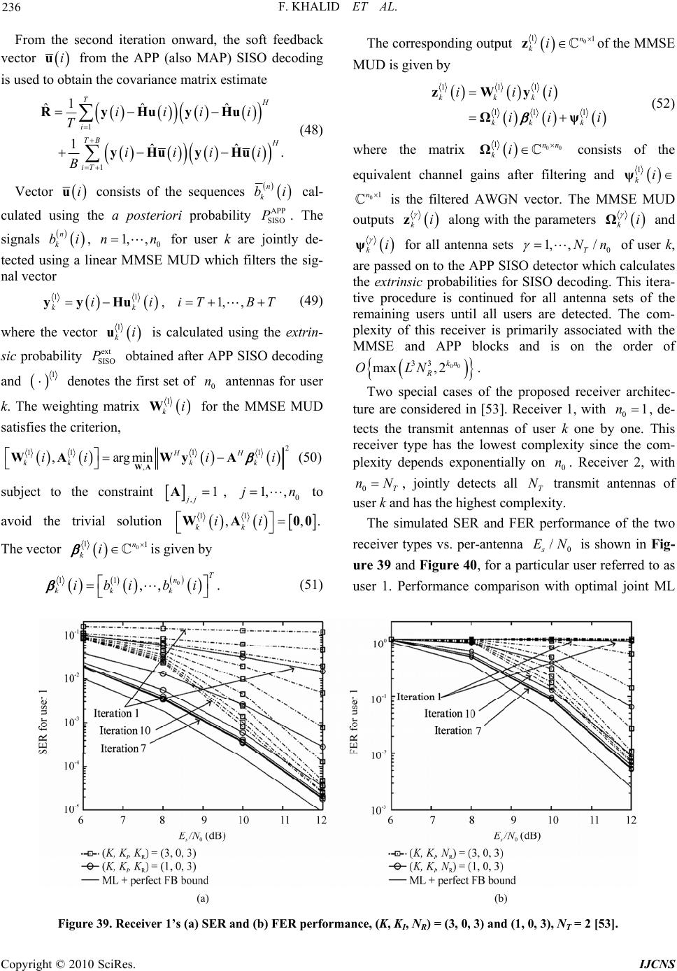 F. KHALID ET AL. 236 From the second itera ve tion onward, the soft feedback ctor iu from the APP (also MAP) SISO decoding is used to obtain the covariance matrix estimate 1 1 1 ˆˆˆ TH 1ˆˆ . i TB H iT iiii T iiii B RyHuyHu yHuyHu (48) Vector iu consists of the sequences n k bi cal- cuing lated usthe a posteriori probability The signals APP SISO P. n bi, 1, ,nn for user k are y de- tected ulin MUD which filters the sig- nal vector k0jointl sing a ear MMSE 1 y1 ,1,, kk iiiTBT y Hu (49) where the vector 1 kiu is calculated using the extrin- obt sic probability ex Pained after APP SISO decoding and t SISO 1 denohe first set of n antennas for user k. Thighting matrix tes t0 e we 1iW f the MMSE MUD satisfies the criterion, kor 2 11 11 , ,argmin HH kkk k iii i WA WAWyA (50) subject to the constraint ,1 jjA, to avoid the trivial solution 0 1, ,jn 11 , kk ii WA 00 ,. The vector 0 11 n i is give kn by 0 11,,. T n kk k ibi bi The corresponding output 0 1 k z1 n i of the MMSE MUD is given by (51) 11 11 1 kkk kk k iii ii i y Ωψ (52) where the matrix 1 zW 00 1nn ki Ω consists of the equivalent channel gains after filtering and 1i k ψ 01n is the filtered AWGN vector. The MMS ts E MUD outpu ki z along with the parameters ki Ω and ki ψ antenna sets 1, ,/Nnfor all0T ser k, ed on to the APP SISO calculates the extrinsic probabilities for SISO decoding. This itera- tive procedure is continued for all antenna sets of the remaining users until all users are detected. The com- plexity of this receiver is primarily associated with the MMSE and APP blocks and is on the order of of u are pass detector which 00 33 max ,2kn R OLN . Two special cases of the proposed receiver architec- ture are considered in [53]. Receiver 1, with 01n , de- tects the transmit antennas of user k one by ones receiver type has the lowest complexity since the com- plexity depends exponentially on 0 n. Receiver 2, with 0T nN . Thi , jointly detects all T N tnsmit antennas of d has the highest compity. The simulated SER and FER perfor ra user k anlex mance of the two re ticular ceiver types vs. per-antenna 0 / s EN is shown in Fig- ure 39 and Figure 40, for a par user referred to as user 1. Performance comparison with optimal joint ML (a) (b) Figure 39. Receiver 1’s (aI R1, 0, 3), NT = 2 [53]. ) SER and (b) FER performance, (K, K, N) = (3, 0, 3) and ( Copyright © 2010 SciRes. IJCNS  F. KHALID ET AL. 237 detection of all T N antennas of user 1 followed by MAP SISO decodi assuming perfect feedback (FB), is also provided. The results are provided for 1 and 10 it- erations for ,, 3,0,3 IR KK N and for 1 and 7 it- erations for with 2N trans- mit antennas p ng ,,KK user. 1,0,3 IR N er K, T I K and R N r e prthe no. of desired users, unknownterferer (UCCI) and BS receive antennas. QPSK modulation is used for transmis- sion and frequency-selective fading is assumed with L = 5 uncorrelated Rayleigh distributed paths. For a suffi- cient no. of iterations, both receivers perform reasonably esent n is igh SNR ws the SER and FER performance of the tw close to the ML receiver, particularly in the h region. Receiver 2 shows slightly better performance than receiver 1. Figure 41 sho o receivers for ,, 2,1,3 IR KK N with 2 T N transmit antennas pesingle t antenna for the unknown interferer (UCCI) i.e. 1 I N r desired user and a ransmit . Two cases of signal-to-UCCI interference ratio (Se considered. For SIR = 3 dB, the signal transmitted from UCCI’s antenna is assumed to have the same power as that of the signal from one antenna of the desired user whereas, for SIR = 0 dB, UCCI’s antenna transmits at IR) ar (a) (b) Figure 40. Receiver 2’s (a) SERI R, 3), NT = 2 [53]. and (b) FER performance, (K, K, N) = (3, 0, 3) and (1, 0 (a) (b) Figure 41. Receiver 1’s and 2’s I R, NT = 2, NI = 1 [53]. (a) SER and (b) FER performance, (K, K, N) = (2, 1, 3) Co pyright © 2010 SciRes. IJCNS 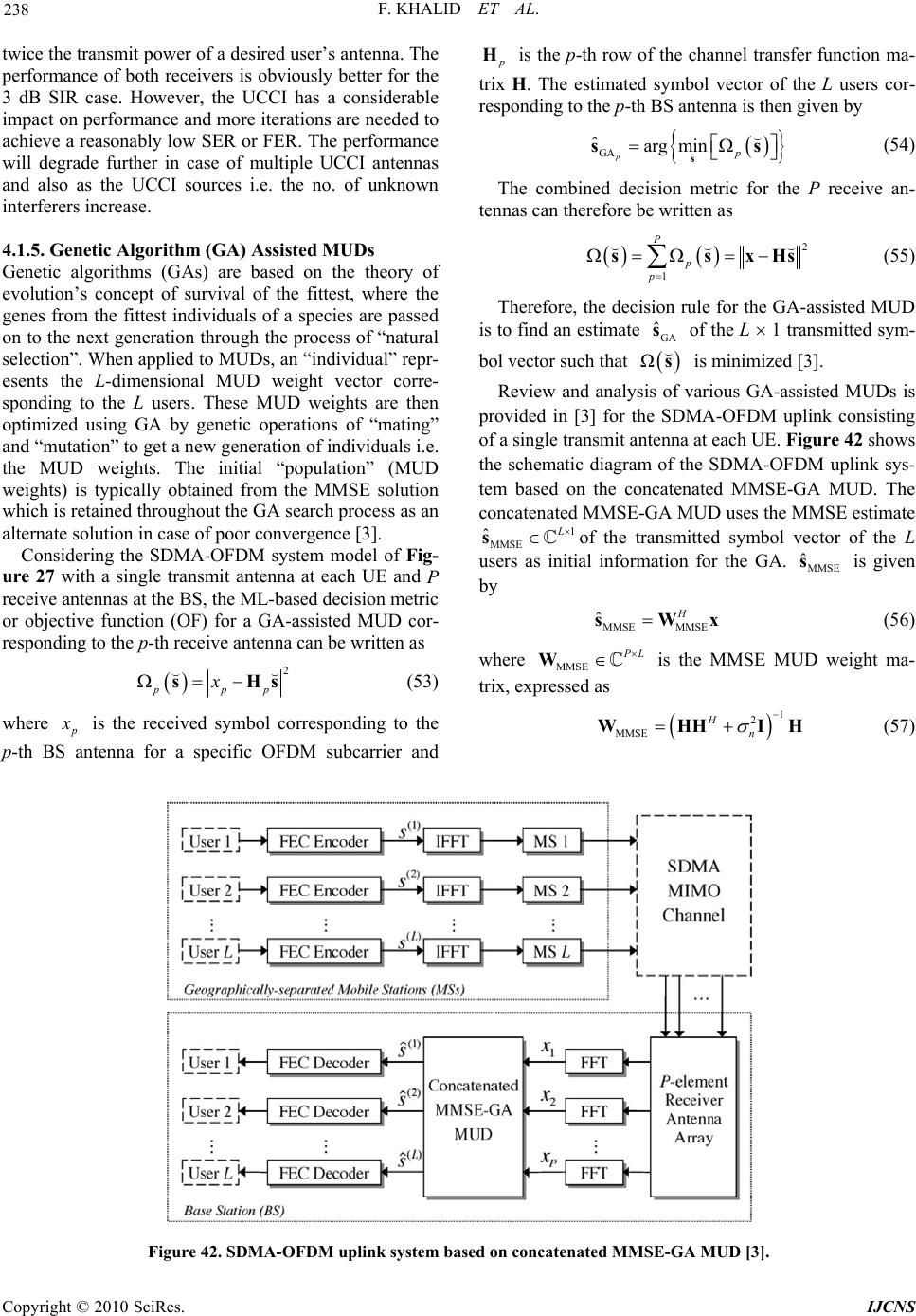 F. KHALID ET AL. 238 twice the ithm (GA) Assisted MUDs ry of transmit power of a desired user’s antenna. The performance of both receivers is obviously better for the 3 dB SIR case. However, the UCCI has a considerable impact on performance and more iterations are needed to achieve a reasonably low SER or FER. The performance will degrade further in case of multiple UCCI antennas and also as the UCCI sources i.e. the no. of unknown interferers increase. .1.5. Genetic Algor4 Genetic algorithms (GAs) are based on the theo evolution’s concept of survival of the fittest, where the genes from the fittest individuals of a species are passed on to the next generation through the process of “natural selection”. When applied to MUDs, an “individual” repr- esents the L-dimensional MUD weight vector corre- sponding to the L users. These MUD weights are then optimized using GA by genetic operations of “mating” and “mutation” to get a new generation of individuals i.e. the MUD weights. The initial “population” (MUD weights) is typically obtained from the MMSE solution which is retained throughout the GA search process as an alternate solution in case of poor conve rgence [3]. Considering the SDMA-OFDM system model of Fig- ure 27 with a single transmit antenna at each UE and P receive antennas at the BS, the ML-based decision metric or objective function (OF) for a GA-assisted MUD cor- responding to the p-th receive antenna can be written as 2 ppp xsHs (53) where p x is the received symbol corresponding to the p-th BS antenna for a specific OFDM subcarrier and p H is the p-th row of the channel transfer function ma- trix H. The estimated symbol vector of the L users cor- responding to the p-th BS antenna is then given by GA ˆarg min pp ss s (54) The combined decision metric for the P receive an- tennas can therefore be written as 2 1 P ss p p xHs (55) Therefore, the decision rule for the GA-assisted MUD is to find an estimate GA ˆ s of the L 1 transmitted sym- bol vector such that sΩ is minimized [3]. Review and analy various GA-assistedsis of MUDs is provided in [3] for the SDMA-OFDM uplink consisting of a single transmit antenna at each UE. Figure 42 shows the schematic diagram of the SDMA-OFDM uplink sys- tem based on the concatenated MMSE-GA MUD. The concatenated MMSE-GA MUD uses the MMSE estimate 1 MMSE ˆ L sof the transmitted symbol vector of the L users as initial information for the GA. MMSE ˆ s is given by MMSE MMSE ˆH sW x (56) e wherMMSE P L W is the M ressed as MSE MUD weight ma- trix, exp 1 2 MMSE Hn HHI H (57) W Figure 42. SDMA-OFDM uplink system based on concatenated MMSE-GA MUD [3]. Copyright © 2010 SciRes. IJCNS 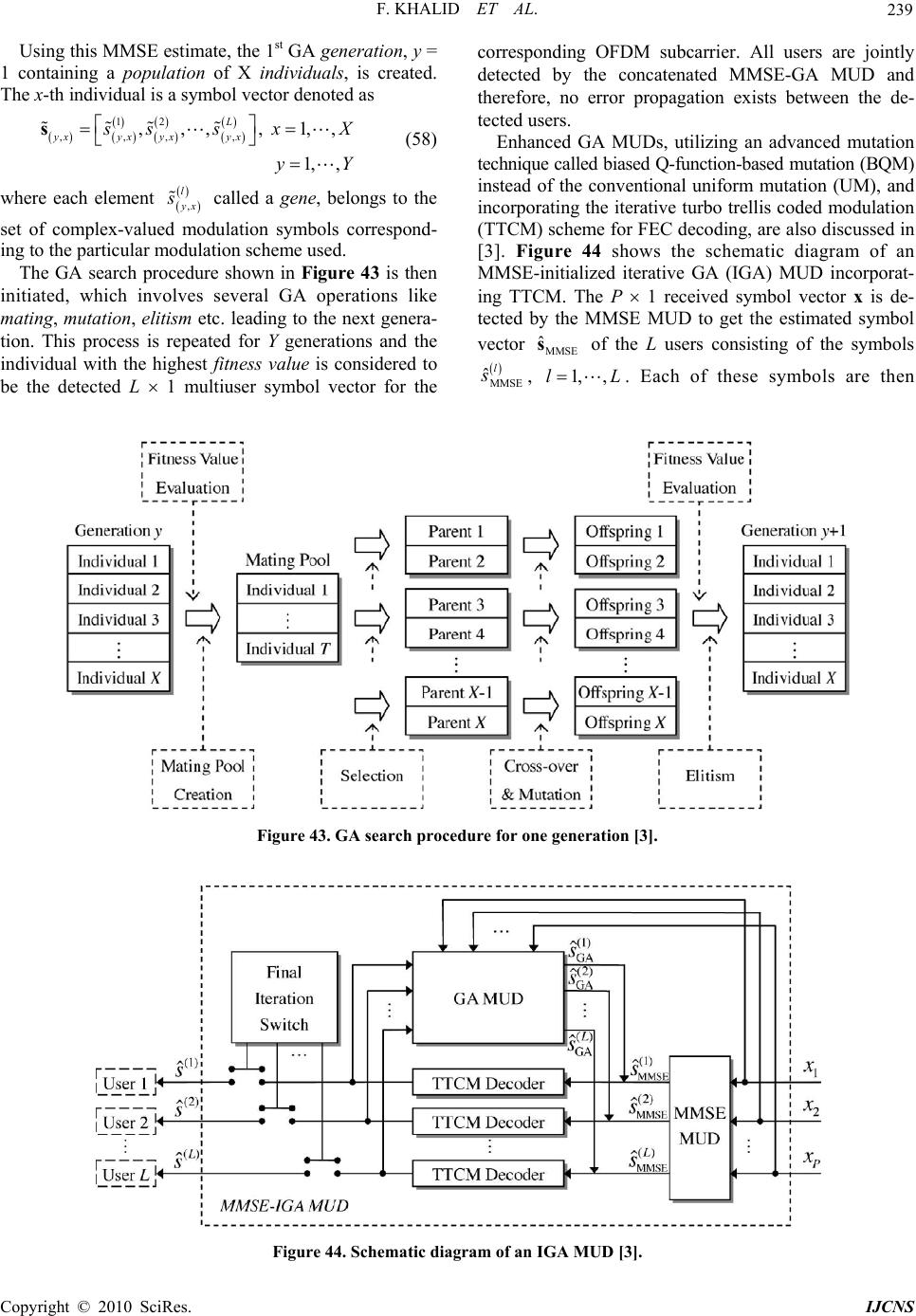 F. KHALID ET AL. 239 Using this MMS 1 E estimate, the 1st GA generation, y = containing a population of X individuals, is created. The x-th individual is a symbol vector denoted as 12 ,,, ,1,, L ,, ,, 1, , yx yx yx yx s ssxX s y Y (58) where each element , l yx s called a gene, belongs to the d mo 43 is then in users are jointly A MUDs, utilizing an advanced mutation te set of complex-valuedulation symbols correspond- ing to the particular modulation scheme used. The GA search procedure shown in Figure itiated, which involves several GA operations like mating, mutation, elitism etc. leading to the next genera- tion. This process is repeated for Y generations and the individual with the highest fitness value is considered to be the detected L 1 multiuser symbol vector for the corresponding OFDM subcarrier. All detected by the concatenated MMSE-GA MUD and therefore, no error propagation exists between the de- tected users. Enhanced G chnique called biased Q-function-based mutation (BQM) instead of the conventional uniform mutation (UM), and incorporating the iterative turbo trellis coded modulation (TTCM) scheme for FEC decoding, are also discussed in [3]. Figure 44 shows the schematic diagram of an MMSE-initialized iterative GA (IGA) MUD incorporat- ing TTCM. The P 1 received symbol vector x is de- tected by the MMSE MUD to get the estimated symbol vector MMSE ˆ s of the L users consisting of the symbols ˆl s, ,L. Each of these symbols are then MMSE 1,l Figure 43. GA search procedure for one generation [3]. Figure 44. Schematic diagram of an IGA MUD [3]. Co pyright © 2010 SciRes. IJCNS 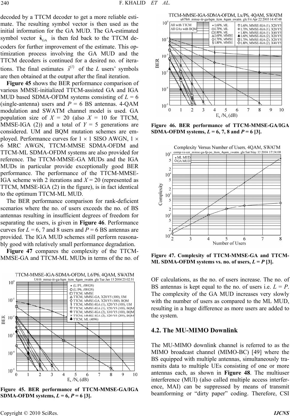 F. KHALID ET AL. 240 ecoded by a TTCM decoder to gedt a more reliable esti- mate. The resulting symbol vector is then used as the initial information for the GA MUD. The GA-estimated symbol vector GA ˆ s is then fed back to the TTCM de- coders for furtheprovement of the estimate. This op- timization process involving the GA MUD and the TTCM decoders is continued for a desired no. of itera- tions. The final estimates r im ˆl s of the L users’ symbols are then obtained at the outpafter the final iteration. Figure 45 shows the BER performance comparison ut of va on for rank-deficient sc M rious MMSE-initialized TTCM-assisted GA and IGA MUD based SDMA-OFDM systems consisting of L = 6 (single-antenna) users and P = 6 BS antennas. 4-QAM modulation and SWATM channel model is used. GA population size of X = 20 (also X = 10 for TTCM, MMSE-IGA (2)) and a total of Y = 5 generations are considered. UM and BQM mutation schemes are em- ployed. Performance curves for 1 1 SISO AWGN, 1 6 MRC AWGN, TTCM-MMSE SDMA-OFDM and TTCM-ML SDMA-OFDM systems are also provided for reference. The TTCM-MMSE-GA MUDs and the IGA MUDs in particular provide exceptionally good BER performance. The performance of the TTCM-MMSE- IGA scheme with 2 iterations and X = 20 (represented as TTCM, MMSE-IGA (2) in the fig ure), is in fact identical to the optimum TTCM-ML MUD. The BER performance comparis enarios where the no. of users exceeds the no. of BS antennas resulting in insufficient degrees of freedom for separating the users, is given in Figure 46. Performance curves for L = 6, 7 and 8 users and P = 6 BS antennas are provided. The IGA MUD schemes still perform reasona- bly good with relatively small performance degradation. Figure 47 compares the complexity of the TTCM- MSE-GA and TTCM-ML MUDs in terms of the no. of Figure 46. BER performance of TTCM-MMSE-GA/IGA SDMA-OFDM systems, L = 6, 7, 8 and P = 6 [3]. Figure 47. Complexity of TTCM-MMSE-GA and TTCM- ML SDMA-OFDM systems vs. no. of users, L = P [3]. = P. he complexity of the GA MUD increases very slowly O downlink channel is referred to as the C) [49] where the simultaneously tra- OF calculations, as the no. of users increase. The no. of BS antennas is kept equal to the no. of users i.e. L T with the number of users as compared to the ML MUD, resulting in a huge difference as more users are added to the system. 4.2. The MU-MIMO Downlink he MU-MIMT MIMO broadcast channel (MIMO-B S equipped with multiple antennas,B nsmits data to multiple UEs consisting of one or more antennas each, as shown in Figure 48. The multiuser interference (MUI) (also called multiple access interfer- ence, MAI) can be suppressed by means of transmit beamforming or “dirty paper” coding. Therefore, CSI Figure 45. BER performance of TTCM-MMSE-GA/IGA SDMA-OFDM systems, L = 6, P = 6 [3]. Copyright © 2010 SciRes. IJCNS 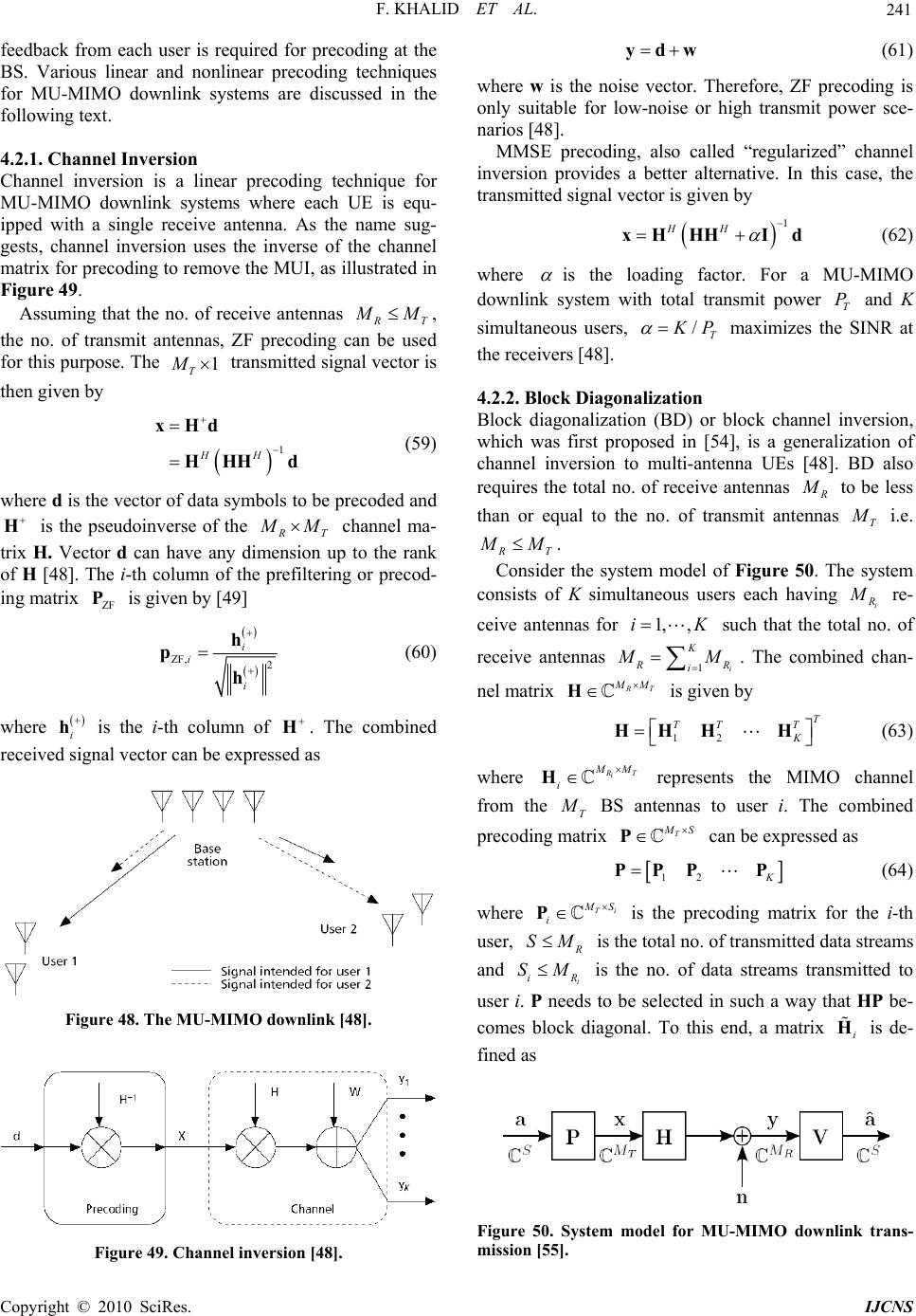 F. KHALID ET AL. 241 nlink systems where each UE is equ- ped with a single receive antenna. As the name sug- es the inverse of the channel feedback from each user is required for precoding at the BS. Various linear and nonlinear precoding techniques for MU-MIMO downlink systems are discussed in the following text. 4.2.1. Channel Inve rsion Channel inversion is a linear precoding technique for MU-MIMO dow ip gests, channel inversion us matrix for precoding to remove the MUI, as illustrated in Figure 49. Assuming that the no. of receive antennas R T M M , the no. of transmit antennas, ZF precoding can be used for this purpose. The 1 T M transmitted signal vector is then give n by 1 H xHd HH d (59) H H where d is the vector of data symbols to be precoded and is the pseudoinverse of the H R T M M channel ma- dimension utrix H. Vector d can have anyp to the rank of H [48]. The i-th column of the prefiltering or precod- ing matrix ZF P is given by [49] ZF, 2 i i i h p h (60) where i h is the i-th column of received signal vector can be expresse H. The combined d as Figure 48. The MU-MIMO downlink [48]. ydw (61) where w is the noise vector. Therefore, ZF precoding is only suitable for low-noise or high transmit power sce- narios [4 8 ]. MMSE precoding, also called “regularized” channel inversion provides a better alternative. In this case, the transmitted signal vector is given by 1 HH xH HHI d (62) where is the loading factor. For a MU-MIMO downlink system with total transmit power T P and K simultaneous /T K P users, maximizes the SINR at th Block diagonalization (BD) or block chan which was first proposed in [54], is a ge e receivers [48]. 4.2.2. Block Diagonalization nel inversion, neralization of channel inversion to multi-antenna UEs [48]. BD also requires the total no. of receive antennas R M to be less than or equal to the no. of transmit antennas T M i.e. R T M M . Consider the system model of Figure 50. The system ers each havingconsists of K simultaneous us re- i R M ceive antennas for 1,, iK such that the total no. of receive antennas 1i K R R i M M . The combined chan- nel matrix R T M M H is given by T TTT 12 K HHHH 63) ( where R T i M M i H represents the MIMO channel from the T M BS antennas to user i. The coined precoding matrix mb T M S Pcan be expressed as 12 K PPPP (64) Ti M S i P Figure 49. Channel inversion [48]. where is the precoding matrix for the user, i-th R SM is th i M e total no. of transmitted data streams and iR S is th eds e nal. To this de- fined as no. of data streams transmitted to user i. P ne to be selected in such a way that HP be- comes block diagois end, a matrix i H Figure 50. System model for MU-MIMO downlink trans- mission [55]. Co pyright © 2010 SciRes. IJCNS 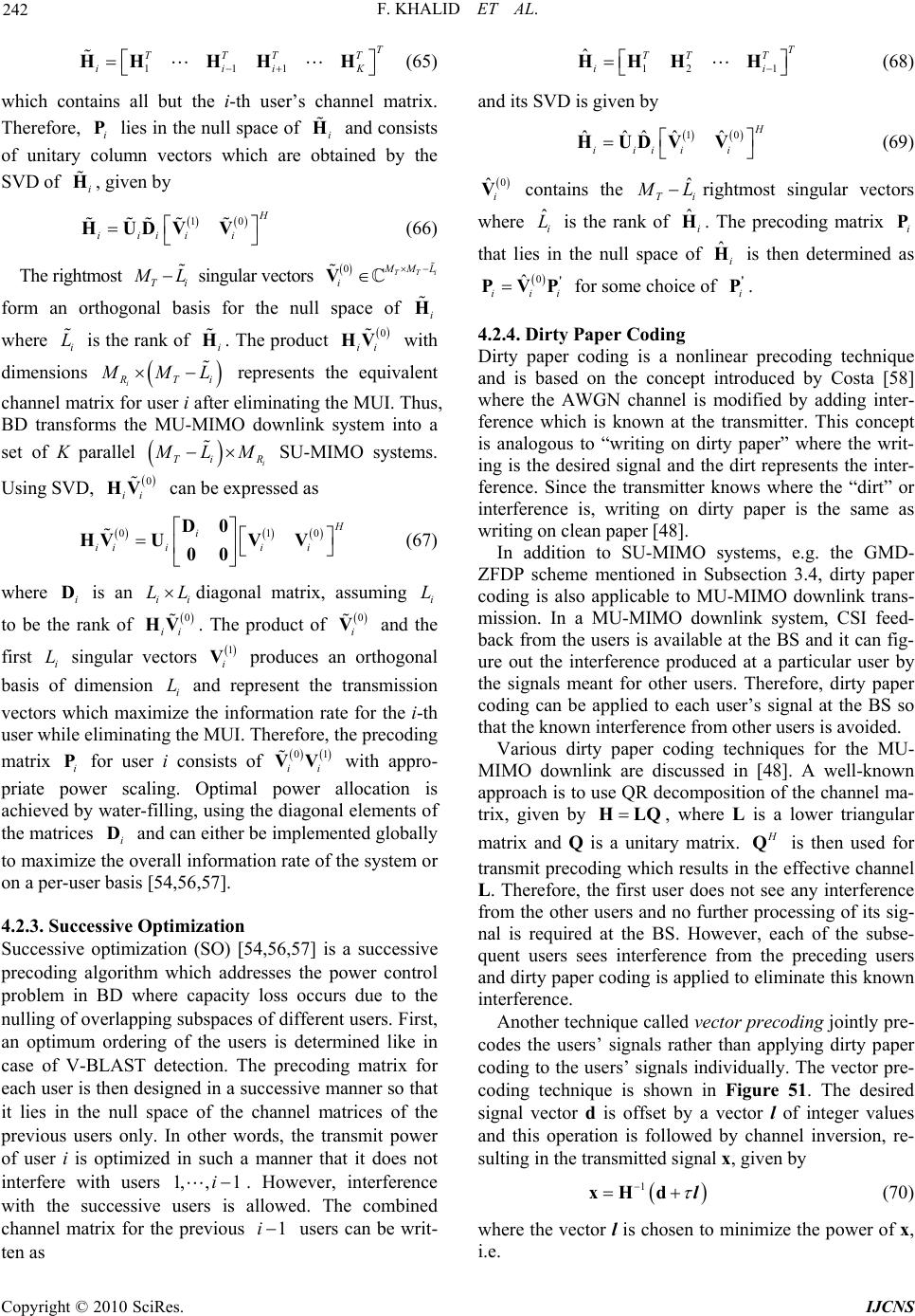 F. KHALID ET AL. 242 ns all but the i-th user’s channel matrix. herefore, lies in the null space of and consists of unitary column vectors which are obtained by the SVD of en by 111 TT TT iiiK HH HHH (65) which contai T Ti P i, giv i H H 10 H iiii i HUDV V ( 6) 6 The rightmos t Ti M L singular vectors 0TTi M ML i V space oform the null an orthogonal basis for f i H where i L is the rank of i H . The product 0 ii HV with dimensions i R Ti M ML represents e equivalent channel matrix for user i after eliminating the MUI. Thus, BD transforms the MU th m into a -MIM Ti O downlink syste set of K parallel i R M LM SU-M Using SD, IMO systems. V 0 ii can HV be expressed as 010 H i iiii i 0 HVV V 00 where i is an ii LLdiagonal matrix, ag i L to be the ran D U (67) ssumin k of D 0 ii HV . The product of 0 i V and the first i L singular vectors 1 i V produces an orthogonal basis of dimensionnt the transmission vectors which maxiation rate for the i-th user while elig the MUI. Therefore, i L a mize t atin er i nd re he inf consists prese orm min ecodi matrix for usof the prng i P 01 ii VV e diagonal ele with l power allocation is ap priate power scaling. ah m [54,56 im ords, the transmit power f user i is optimized in such a manner that it does not wever, interference pro- ents of ly Optim ng tachieved by water-filling, usi the mats i D and can either be implemented global to maximize the overall information rate of the system or on a per-user basis,57]. 4.2.3. Successive Optization Successive optimization (SO) [54,56,57] is a successive precoding algorithm which addresses the power control problem in BD where capacity loss occurs due to the nulling of overlapping subspaces of different users. First, an optimum ordering of the users is determined like in case of V-BLAST detection. The precoding matrix for each user is then designed in a successive manner so that it lies in the null space of the channel matrices of the previous users only. In other w rice o interfere with users 1, ,1i. Ho with the successive users is allowed. The combined channel matrix for the previous 1i users can be writ- ten as 121 ˆT TTT ii HHH H (68) and its SVD is given by 10 ˆˆˆˆˆ H iiii i HUDV V (69) 0 ˆi V contains the ˆ Ti M L rightmost singular vectors where ˆi L is the rank iThe precoding matrix i P that lies in the null space of ˆi His then determined as of ˆ H. 0 ˆ i ' PV ii for som 4.2.4. Dirty Paper Coding nonlinear precoding technique and is based on the concept introduced by Costa [58] where the AWGN channel is modifi ference which is known at the transmitter. This concept is anting on d rrty writing on clean In addityss, e.g. the GMD- FDP scheme mentioned in Subsection 3.4, dirty paper MU-MIMO downlink trans- position of the channel ma- tri P e choice of i' P. Dirty paper coding is a ed by adding inter- alogous to “wriirty paper” where the writ- ing is the desired signal and the dirt represents the inter- ference. Since the transmitte knows where the “dirt” or interference is, writing on di paper is the same as paper [48]. ion to SU-MIMO stem Z coding is also applicable to mission. In a MU-MIMO downlink system, CSI feed- back from the users is available at the BS and it can fig- ure out the interference produced at a particular user by the signals meant for other users. Therefore, dirty paper coding can be applied to each user’s signal at the BS so that the known interfere nce fr om other users is avoide d. Various dirty paper coding techniques for the MU- MIMO downlink are discussed in [48]. A well-known approach is to use QR decom x, given by HLQ, where L is a lower triangular matrix and Q is a unitary matrix. H Q is then used for transmit precoding which results in the effective channel L. Therefore, the first user does not see any interference from the other users and no further processing of its sig- nal is required at the BS. However, each of the subse- quent users sees interference from the preceding users and dirty paper coding is applied to eliminate this known interference. Another technique called vector precoding jointly pre- codes the users’ signals rather than applying dirty paper coding to the usals individually. The vector pre- coding technique is shown in Figure 51. The desired signal vector d is offset by a vector l of integer values and this operation is followed by channel inversion, re- sulting in the transmitted signal x, given by ers’ sign 1 xHdl (70) where the vector l is chosen to minimize the power of x, i.e. Copyright © 2010 SciRes. IJCNS 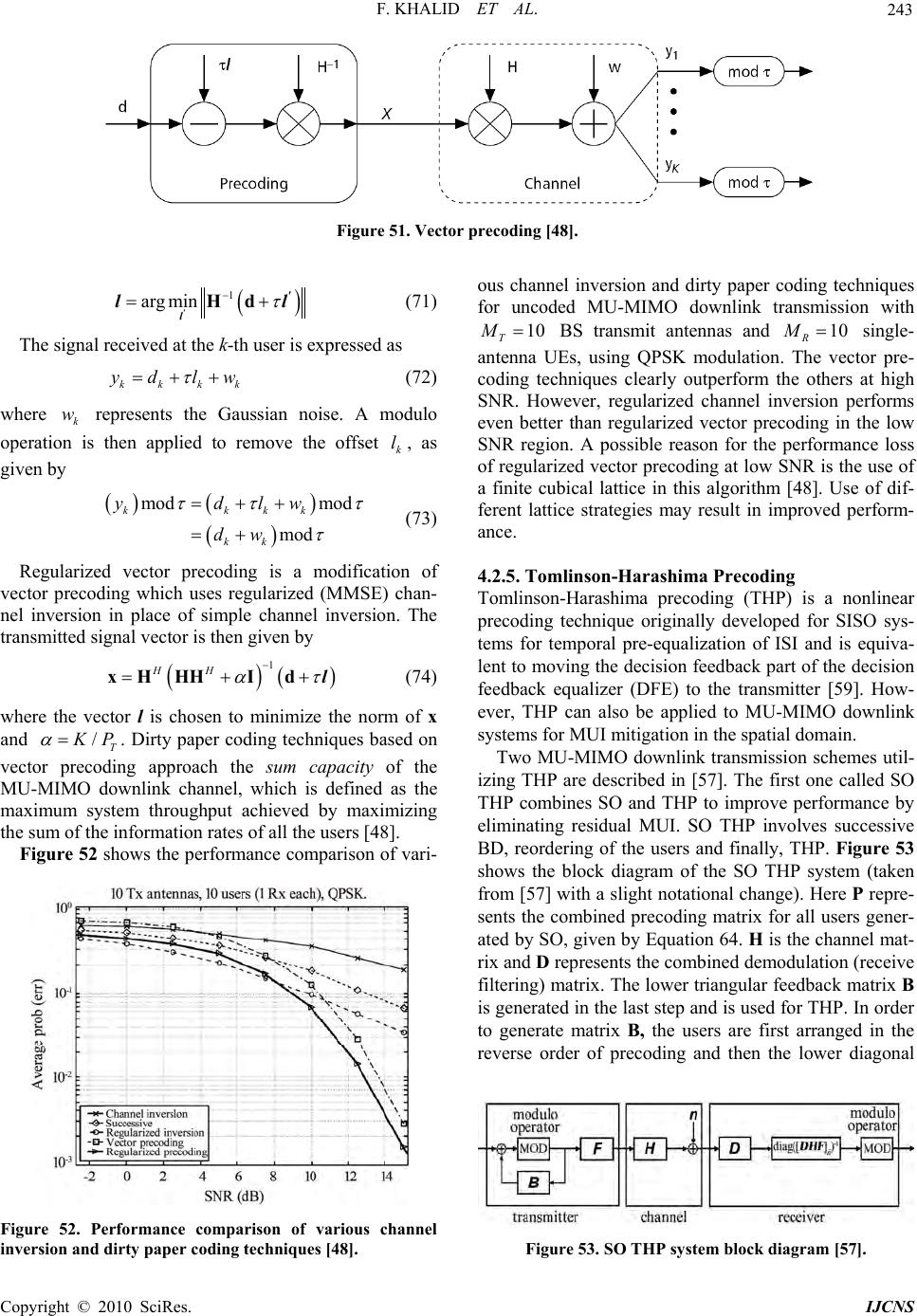 F. KHALID ET AL. Copyright © 2010 SciRes. IJCNS 243 Figure 51. Vector precoding [48]. 1 argmin Hd ' ' l ll (71) The signal received at the k-th user is expressed as kkkk yd lw here represents the Gaussian noise. A modulo applied to remove t given by (72) wk w operation is then he offset k l, as mod mod kkkk ydlw k d mod k w (73) Regularized vector precoding is a modification of vector precoding which uses regularized (MMSE) han- nel invers transmitte c ion in place of simple channel inversion. The d signal vector is then given by 1 HH xHHHIdl w (74) here the vector l is chosen to minimize the norm of x and /T K P . Dirty paper coding techniques based on vector precoding approach the sum capacity of the MU-MIMO downlink channel, which is defined as the maximum system throughput achieved by maximizing the sum of the information rates of all the us Figure 52ers [48]. shows the performance comparison of vari- Figure 52. Performance comparison of various channel inversion and dirty paper co ding te c hnique s [48]. ous channel inversion and dirty paper coding techniques for uncoded MU-MIMO downlink transmission with 10 T M BS transmit antennas and single- antenna UEs, using QPSK modulation. Th vector pre- ues clearly outperform the others at high r, regularized channel inversion performs even better than regularized vector precoding in the low SNR region. A possible reason for the performance loss of regularized vector precoding at low SNR is the use of a finite cubical lattice in this algorithm [48]. Use of dif- ferent lattice strategies may result in improved perform- ance. 4.2.5. Tomlinson-Harashima Precoding Tomlinson-Harashima precoding (THP) is a nonlinear precoding technique originally developed for SISO sys- tems for temporal pre-equalization of ISI and is equiva- lent to moving the decision feedback part of the decision feedback equalizer (DFE) to the transmitter [59]. How- ever, THP can also be applied to MU-MIMO downlink systems for MUI mitigation in the spatial domain. T 10 R M e coding techniq SNR. Howeve Two MU-MIMO downlink transmission schemes util- izing THP are described in [57]. The first one called SO THP combines SO and THP to improve performance by eliminating residual MUI. SO THP involves successive BD, reordering of the users and finally,HP. Figure 53 shows the block diagram of the SO THP system (taken from [57] with a slight notational change). Here P repre- sents the combined precoding matrix for all users gener- ated by SO, given by Equation 64. H is the channel mat- rix and D represents the combined demodulation (receive filtering) matrix. The lower triangular feedback matrix B is generated in the last step and is used for THP. In order to generate matrix B, the users are first arranged in the reverse order of precoding and then the lower diagonal Figure 53. SO THP system block diagram [57]. 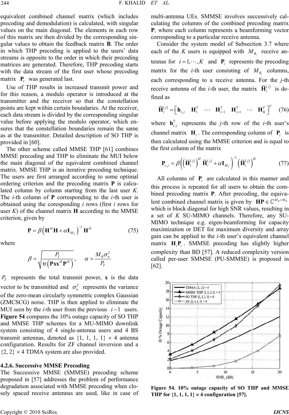 F. KHALID ET AL. 244 ngular va s at the transmitter. Detailed description of SO THP is provided in [60]. The other scheme called MMSE THP [61] combines MMSE precoding and THP to eliminate the MUI below the main diagonal of the equivalent combined channel matrix. MMSE THP is an iterative precoding technique. The users are first arranged according to some optima orderi alcu- equivalent combined channel matrix (which includes precoding and demodulation) is calculated, with si lues on the main diagonal. The elements in each row of this matrix are then divided by the corresponding sin- gular values to obtain the feedback matrix B. The order in which THP precoding is applied to the users’ data streams is opposite to the order in which their precoding matrices are generated. Therefore, THP precoding starts with the data stream of the first user whose precoding matrix 1 P was generated last. Use of THP results in increased transmit power and for this reason, a modulo operator is introduced at the transmitter and the receiver so that the constellation points are kept within certain boundaries. At the receiver, each data stream is divided by the corresponding singular value before applying the modulo operator, which en- sures that the constellation boundaries remain the same a l ng criterion and the precoding matrix P is c lated column by column starting from the last user K. The i-th column of P corresponding to the i-th user is obtained using the coresponding i rows (first i rows for user K) of the channel matrix H according to the MMSE criterion, given by 1 T H H M PHHIH (75) where 2 , tr R n M T P HH T P PxxP T P represents the total transmit power, x is the data vector to be transmitted and 2 n represents the variance of the zero-mean circularly symmetric c omplex Gaussian (ZMCSCG) noise. THP is then applied to eliminate the MUI seen by the i-th user from the previous 1i users. Figure 54 compares the 10% outage capacity of SO THP and MMSE THP schemes for a MU-MIMO downlink system consisting of 4 single-antenna users and 4 BS transmit antennas, denoted as {1, 1, 1, 1} 4 antenna configuration. Results for ZF channel inversion and a {2, 2} 4 TDMA system are also provided. 4.2.6. Successive MM SE Pre coding The Successive MMSE (SMMSE) precoding scheme proposed in [57] addresses the problem of performance degradation associated with MMSE precoding when clo- sely spaced receive antennas are used, like in case of multi-antenna UEs. SMMSE involve culating the columns of the combine re each column represents a beamforming vector to a particular receive antenna. Consider the system model of Subsection7 where each of the K users is equipped with s successively cal- d precoding matrix P, whe corresponding 3. i R M receive an- tennas for 1, ,iK and i P represents the precoding matrix for the i-th user consisting of i R M columns, each corresponding to a receive antenna. For the j-th receive antenna of the i-th user, the matrix j i H is de- fined as ,111 T jTTT T iijii K HhH HHH (76) where , T ij h represents the j-th row of the i-th user’s channel matrix i H. The correspond ing colu mn of i P is then calculated using the MMSE criterion and is equal to e first column of the matrix th 1 ,T H H jj j ijiiMi PHHIH (77) All columns of i P are calculated in this manner and this process is repeated for all users to obtain the com- bined precoding matrix P. After precoding, the equiva- lent combined channel matrix is given by R R M M HP which is block diagonal for high SNR values, resulting in ligh a ing or Daxim applied th rop set of K SU-MIMO channels. Therefore, any SU- MIMO technique e.g. eigen-beamformfor capacity maximization for mum diversity and array gain can be the i-t user’s equivalent channel matrix ii HP. SMMSE precoding has stly higher complexity than BD [57]. A reduced complexity version called per-user SMMSE (PU-SMMSE) is posed in [62]. ET o Figure 54. 10% outage capacity of SO THP and MMSE THP f or {1, 1, 1, 1} 4 configuration [57]. Copyright © 2010 SciRes. IJCNS 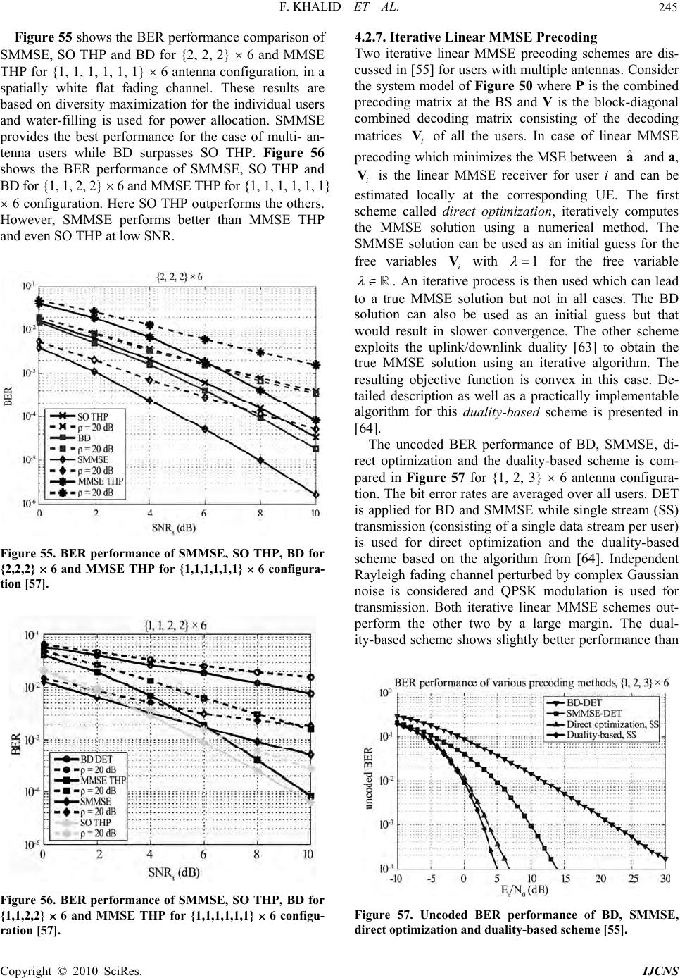 F. KHALID ET AL. 245 es the best performance for the case of multi- an- tenna users while BD surpasses SO THP. Figure 56 hows the BER performance of SMMSE, SO THP and BD for {1, 1, 2, 2} 6 and MMSE THP for {1, 1, 1, 1, 1, 1} 6 configuration. Here SO THP outperforms the others. However, SMMSE performs better than MMSE THP and even SO THP at low SNR. Figure 55 shows the BER performance comparison of SMMSE, SO THP and BD for {2, 2, 2} 6 and MMSE THP for {1, 1, 1, 1, 1, 1} 6 antenna configuration, in a spatially white flat fading channel. These results are based on diversity maximization for the individual users and water-filling is used for power allocation. SMMSE provid s Figure 55. BER performance of SMMSE, SO THP, BD for {2,2,2} 6 and MMSE THP for {1,1,1,1,1,1} 6 configura- tion [57]. Figure 56. BER performance of SMMSE, SO THP, BD for {1,1,2,2} 6 and MMSE THP for {1,1,1,1,1,1} 6 configu- ration [57]. 4.2.7. Iterative Linear MMSE Precoding Two iterative linear MMSE precoding schemes are dis- cussed in [55] for users with multiple antennas. Consider the system model of Figure 50 where P is the combined precoding matrix at the BS and V is the block-diagonal combined decoding matrix consisting of the decoding matrices of all the users. In case of linear MMSE precodinich minimizes the MSE between and a, is the linear MMSE receiver for user i ad can be ated locally at the corresponding UE. Te first edirect optimization, iteratively computes using a numerical me. The SMMSE soltion can be used as an initial guess for the with i V g wh called the MMSE solution u variables ˆ a n h thod i V estim schem free i V1 for the free variable . An iterative process is then used which can lead to a true MMSE solution but not in all cases. The BD he uplink/downlink duality [63] to obtain the ue MMSE solution using an iterative algorithm. The resulting objective function is convex in this case. De- tailed description as well as a practically implementable algorithm for this duality-based scheme is presented in [64]. The uncoded BER performance of BD, SMMSE, di- rect optimization and the duality-based scheme is com- pared in Figure 57 for {1, 2, 3} 6 antenna configura- tion. The bit error rates are averaged over all users. DET is applied for BD and SMMSE while single stream (SS) transmission (consisting of a single data stream per user) is used for direct optimization and the duality-based scheme based on the algorithm from [64]. Independent Rayleigh fading channel perturbed by complex Gaussian noise is considered and QPSK modulation is used for transmission. Both iterative linear MMSE schemes out- perform the other two by a large margin. The dual- ity-based scheme shows slightly better performance than solution can also be used as an initial guess but that would result in slower convergence. The other scheme exploits t tr Figure 57. Uncoded BER performance of BD, SMMSE, direct optimization and duality-based scheme [55]. Co pyright © 2010 SciRes. IJCNS  F. KHALID ET AL. 246 on iffere conve interesting MU-MIMO downlink transmission scheme ased solely on instantaneous channel norm feedback is proposed in [65]. MU-MIMO configuration with multi- ple base station (BS) antennas and a single antenna at each UE is considered. The proposed scheme can pro- vide high multiuser diversity gain by optimizing resource allocation at the BS while simply utilizing the instanta- neous channel norm feedback from the UEs. Figure 59 shows the operatio n of the propo sed system at the transmitter (BS). The BS initially transmits or- thogonal pilot signals on all transmit antennas which are used by each UE to estimate the received signal energy i.e. the squared norm of the channel vector given by direct optimizati. This dnce is due to the non- x objective function used for direct optimization which occasionally causes the optimization routine to undesired minima. BD provides the worst performance because of the zero-forcing constraint. Figure 58 shows the coded BER performance of these precoding schemes. A rate 1/2 turbo code is used for error correction. OFDM based transmission is considered where the precoding is applied on a per-subcarrier basis. The ITU Vehicular A channel model is used. Direct op- timization and the duality-based scheme provide almost identical performance in this case, far better than BD and SMMSE. 4.2.8. Partial CSI Feedback Transmit precoding for downlink MU-MIMO transmis- sion requires CSI feedback from the users. However, feedback information consisting entirely of the current state of the channel may not be accurate enough in case of rapidly varying channels. Downlink transmission sche- mes that utilize partial CSI consisting of long-term cha- nnel statistics along with some instantaneous channel information like SNR, SINR etc. provide a solution to this problem while reducing the feedback overhead. An b Figure 58. optimization an Figure 59. System operation at the transmitter [65]. 2 kk h (78) where k h represents the channel vector for the k-th UE from the UEs scheduled for transmission. k is cate- gorized as channel gain information (CGI) in [65]. This quantity is then fed back to the BS. The BS estimates the long-term channel statistics including the channel mean and the channel covariance matrix, defined as ˆE| kkk hh (79) ˆE| H kkkk Qhh (80) This slow varying statistical information is referred to as channel distribution information (CDI). The CGI feed - back along with the CDI is used to estimate the SINR and the optimized beamforming weight vectors for each of the UEs scheduled for transmission. The SINR for user k is estimated as 2 \ ˆ SINR H kkk kH iki k ik wQw wQw (81) where is the corresponding beamforming vector, is the MMSE estimate of the sig- nce power ratio (SIR) k w ˆ H i k wQ -inter k ˆki i w nal-to fere and HH kiik ki whh w is the AWGN power. The actual data transmission to the scheduled users then begins. Another set of users can later be scheduled to achieve better fairness and this process goes on until the CGI becomes outdated. At this point, BS transmits the pilot signals again and the whole process is repeated. simultaneous users for MU-MIMO downlink transmission with accep- table performance. The performance degrades in rank- deficient scenarios and also when the users are spatially correlated. In case of multi-antenna users, the no. of us ers en sser. In practical situations, the BS would generally erve a larger no. of user support. Therefore, an eff du 4.2.9. Multiuser Scheduling The BS can only support a limited no. of - that can be supported simultaneously becomes ev le ss than it can simultaneously icient scheduling algorithm is required to select the group of users that will be spatially multiplexed by the BS at a certain time and frequency. The scheling algorithm should avoid grouping spa- tially correlated users and maximize system performance while maintaining fairness toward all users. Fairness Coded BER performance of BD, SMMSE, direct d duality-based scheme [55]. Copyright © 2010 SciRes. IJCNS 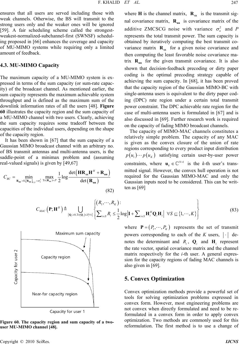 F. KHALID ET AL. Copyright © 2010 SciRes. IJCNS 247 mit to the strong users only and the wea [59]. A fair scheduling schem weakest-normalized-subchannel-fir ing proposed in [66] enhances the c of ty of a MU-MIMO system is ex- pressed in terms of the sum capacity (or sum-rate capac- ity) of the broadcast channel. As mentioned ea sum capacity represents the maximum achievable system throughput and is defined as the maximum sum of the k i 60 illustrates th a MU-MIMO coff between the s, depending on the shape ensures that all users are served including those with weak channels. Otherwise, the BS will transwhere H is the channel matrix, xx R is the transmit sig- nal covariance matrix, nn R is covariance matrix of the additive ZMCSCG noise with variance 2 n and P represents the total transmit power. The sum capacity is obtained by iteratively computing the best transmit co- variance matrix xx R for a given noise covariance and then computing the least favorable noise covariance ma- trix nn R for the given transmit covariance. It is also shown that decision-feedback precoding or dirty paper ker ones will be ignored e called the strongest- st (SWNSF) schedul- overage and capacity MU-MIMO systems while requiring only a limited amount of feedb ac k. 4.3. MU-MIMO Capacity The maximum capacico n total transmit power constraint. The DPC achievable rate region for the case of multi-antenna users is formulated in [67] and i also discussed in [69]. Further research work is required on the capacity of fading MIMO broadcast channels. channels co cis ding is the optimal precoding strategy capable of achieving the sum capacity. In [68], it has been proved that the capacity region of the Gaussian MIMO-BC with single-antenna users is equivalent to the dirty paper cod- ing (DPC) rate region under a certai rlier, the downlinnformation rates of all the users [48]. Figure e capacity region and the sum capacity of hannel with two users. Clearly, achieving the sum capacity requires some trade capacities of the individual user of s the capacity region. It has been shown in [67] that the sum capacity of a Gaussian MIMO broadcast channel with an arbitrary no. of BS transmit antennas and multi-antenna users, is the saddle-point of a minimax problem and (assuming eal-valued signals) is given by [49,67] r The capacity of MIMO-MAC nstitutes a relatively simple problem. The capacity of any MAC is given as the convexlosure of the union of rate regions corr esponding to every produ ct input dtribution 1 K pu pu satisfying certain user-by-user power constraints, where 1N k u is the k-th user’s trans- mitted signal. Hoer, the convex hull operation is not required for the Gaussian MIMO-MAC and only the Gaus inputs need to be considered. This can be writ- wev sian 2 ,Tr( ) 0, min max log 2det n kk BC P C xx nn nn xx nn R RR nn R (82) det HHR HR 1 ten as [69] g 1, , H iii iSSK 1 0,Tr ,, ;1 iii K H MAC Pi i iS RR CR : lo 2 IHQ H (83) QQ PH where 1,, K PPP represents the set of transmit powers corresponding to each of the K users, de- notes the determinant and i R, i Q and i H represent the rate vector, spatial covariance matrix and the channel matrix respectively for the i-th user. A general expres- sion for the capacity regions of fading MAC channels is also given in [69]. ptimization Convex optimization methods provide a powerful set of tools for solving optimization problems expressed in convex form. However, most engineering problems are not convex 5. Convex O when directly formulated and need to be re- formulated in a convex form in order to apply convex optimization. Two methods are commonly used for this reformulation. The first method is to use a change of Figure 60. The capacity region and sum capacity of a two- user MU-MIMO channel [48]. 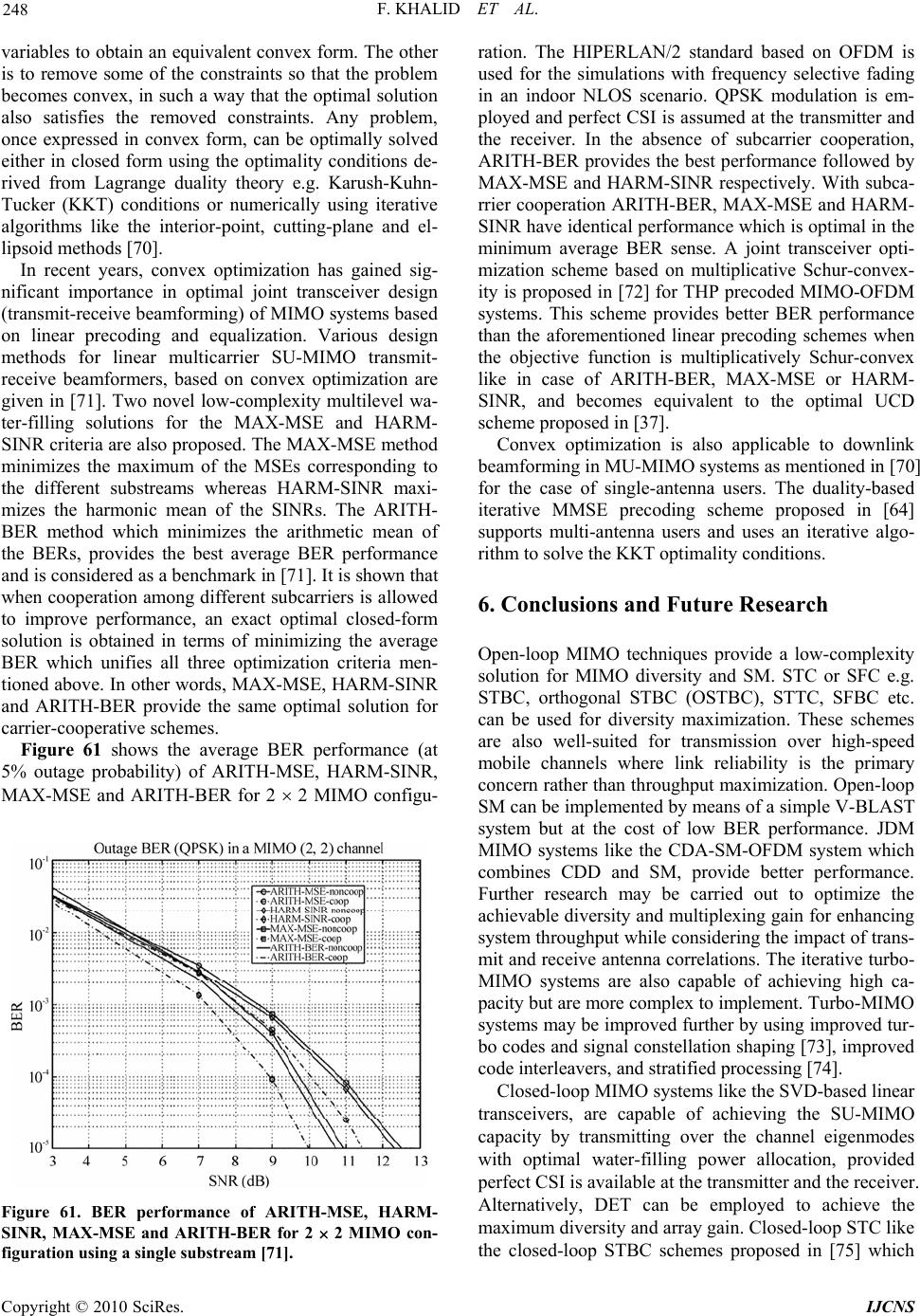 F. KHALID ET AL. 248 variables to obtain an equivalent convex form. The other is to remove some of the constraints so that the problem becomes convex, in such a way that the optimal solution also satisfies the removed constraints. Any problem, once expressed in convex form, can be optimally solved either in closed form using the optimality conditions de- rived from Lagrange duality theory e.g. Karush-Kuhn- ucker (KKT) conditions or numerically using iterative algorithms like the interior-point, cutting-plane and el- lipsoid methods [70]. In recent years, convex optimization has gained sig- nificant importance in optimal joint transceiver design (transmit-receive beamforming) of MIMO systems based on linear precoding and equalization. Various design methods for linear multicarrier SU-MIMO transmit- receive beamformers, based on convex optimization are given in [71]. Two novel low-complexity multilevel wa- ter-filling solutions for the MAX-MSE and HARM- SINR criteria are also proposed. The MAX-MSE method minimizes the maximum of the MSEs corresponding to the different substreams whereas HARM-SINR maxi- mizes the harmonic mean of the SINRs. The ARITH- BER method which minimizes the arithmetic mof oration am ave oimi s the average BER performance (at ARITH-MSE, HARM-SINR, or 2 2 MIMO configu- T ean the BERs, provides the best average BER performance and is considered as a benchmark in [71]. It is shown that peowhen cong different subcarriers is allowed to improve performance, an exact optimal closed-form solution is obtained in terms of minimizing the rage BER which unifies all threeptzation criteria men- tioned above. In other words, MAX-MSE, HARM-SINR and ARITH-BER provide the same optimal solution for carrier-cooperative schemes. Figure 61 show % outage probability) of 5 MAX-MSE and ARITH-BER f Figure 61. BER performance of ARITH-MSE, HARM- SINR, MAX-MSE and ARITH-BER for 2 2 MIMO con- figuration using a single substream [71]. rrier cooperation ARITH-BER, MAX-MSE and HARM- SINR have identical performance which is optimal in the minimum average BER sense. A joint transceiver opti- mization scheme based on multiplicative Schur-convex- ity is proposed in [72] for THP precoded MIMO-OFDM systems. This scheme provides better BER performance than the aforementioned linear precoding schemes when the objective function is multiplicatively Schur-convex like in case of ARITH-BER, MAX-MSE or HARM- SINR, and becomes equivalent to the optimal UCD scheme proposed in [37]. Convex optimization is also applicable to downlink beamforming in MU-MIMO systems as mentioned in [70] for the case of single-antenna users. The duality-based iterative MMSE precoding scheme proposed in [64] supports multi-antenna users and uses an iterative algo- rithm to solve the KKT optimality conditions. 6. Conclusions and Future Research ration. The HIPERLAN/2 standard based on OFDM is used for the simulations with frequency selective fading in an indoor NLOS scenario. QPSK modulation is em- ployed and perfect CSI is assumed at the transmitter and the receiver. In the absence of sub ARITH-BER provides the best performance followed by MAX-MSE and HARM-SINR respectively. With subca- an be used for diversity maximization. These schemes are also well-suited for transmission over high-speed mobile channels where link reliability is the primary concern r ather than throu ghput maximization. Op en-loop SM can be implemented by means of a simple V-BLAST system but at the cost of low BER performance. JDM MIMO systems like the CDA-SM-OFDM system which combines CDD and SM, provide better performance. Further research may be carried out to optimize the achievable diversity and multiplexing gain for enhancing system throughput wh ile considering the impact of trans- mit and receive antenna correlations. The iterative turbo- MIMO systems are also capable of achieving high ca- pacity but are more complex to implement. Turbo-MIMO systems may be improved further by using improved tur- bo codes and signal constellation shaping [73], improved code interleavers, and stratified processing [74]. nel eigenmodes carrier cooperation, Open-loop MIMO techniques provide a low-complexity solution for MIMO diversity and SM. STC or SFC e.g. STBC, orthogonal STBC (OSTBC), STTC, SFBC etc. c Closed-loop MIMO systems like the SVD-based linear transceivers, are capable of achieving the SU-MIMO capacity by transmitting over the chan with optimal water-filling power allocation, provided perfect CSI is available at the transmitter and the receiver. Alternatively, DET can be employed to achieve the maximum diversity and array gain. Closed-loop STC like the closed-loop STBC schemes proposed in [75] which Copyright © 2010 SciRes. IJCNS  F. KHALID ET AL. 249 perform- provides tems. The igher complexity Turbo-MUD scheme achieves better le com- pl support more than two transmit antennas, also provide diversity maximization. The GMD-MIMO scheme de- composes the MIMO channel into identical subchannels and attempts to combine MIMO diversity and SM in an optimal manner. MAX-MSE, HARM-SINR and ARITH-BER methods based on convex optimization provide optimal average BER performance for multi- stream transmission when subcarrier cooperation is al- lowed. However, the GMD and convex optimization approaches assume the availability of full CSI at the transmitter and the receiver which is not always the case e.g. in rapidly changing mobile channels. Therefore, the performance of these schemes with imperfect feedback needs to be evaluated for practical implementation. Use of convex optimization methods for designing optimal linear transceivers utilizing partial CSI also need to be investigated. For the MU-MIMO uplink, the LAST-MUD scheme ased on V-BLAST detection provides goodb ance for CDMA systems. The SMMSE MUD acceptable performance for MIMO-OFDM sys h performance and can jointly detect the transmit antennas of each multi-antenna user. Use of different turbo detec- tion strategies, joint detection of all users and extension to multicarrier systems may be investigated in future. The GA-assisted MUDs, particularly the TTCM-assisted IGA-MUD provide near-ML detection performance for SDMA-OFDM systems and also perform reasonably well in certain rank-deficient scenarios. The complexity is high but increases slowly with the no. of users as compared to the ML-MUD. GA-assisted MUDs can also incorporate joint channel estimation and symbol detec- tion. Future research work may include extending the GA-assisted MUD schemes to support multi-antenna users and development of more efficient GAs to reduce system complexity. Use of artificial intelligence (AI) techniques like the radial basis function (RBF) based artificial neural networks (ANNs) should also be ex- plored for multiuser detection. Coming to the MU-MIMO downlink, SMMSE pre- coding performs reasonably well with manageab exity. The nonlinear dirty paper coding techniques are capable of achieving the sum capacity of Gaussian mul- tiuser channels with single-antenna users. The iterative linear MMSE techniques like direct optimization and the duality-based scheme which uses convex optimization, provide excellent uncoded and coded BER performance for single stream transmission. Further research is re- quired to develop MU-MIMO downlink transmission schemes capable of supporting SM for individual multi-antenna mobile users. Transmission schemes based on partial CSI which require minimal CSI feedback from the users represent the most suitable choice for practical implementation. Convex optimization tools might be useful in designing joint transmit-receive beamforming systems less prone to errors resulting from imperfect CSI. Research efforts are also needed for developing efficient multiuser scheduling schemes that maintain fairness to the users while minimizing the loss of system capacity. Determining the sum capacity and capacity regions for fading MU-MIMO downlink channels with multi-an- tenna users is als o an area for future research. Accurate channel estimation is of prime importance in MIMO communications. Channel estimation errors may result in severe performance degradation. Therefore, research efforts are continuing for further improvements in this domain. A broadband wireless transmission tech- nique called orthogonal frequency- and code-division multiplexing (OFCDM) [76] has recently gained promi- nence as a better alternative to OFDM. OFCDM readily supports MIMO techniques and extensive research would be required to realize the full potential of MIMO- OFCDM systems. 7. References [1] D. Gesbert, M. Shafi, D.-S. Shiu, P. J. Smith, and A. Naguib, “From theory to practice: An overview of MIMO space-time coded wireless systems,” IEEE Journal on Selected Areas in Communications, Vol. 21, No. 3, pp. 281–302, April 2003. [2] Y. Jiang, J. Li, and W. W. Hager, “Joint transceiver de- sign for MIMO communications using geometric mean decomposition,” IEEE Transactions on Signal Processing, Vol. 53, No. 10, pp. 3791–3803, October 2005. [3] M. Jiang and L. Hanzo, “Multiuser MIMO-OFDM for next-generation wireless systems,” Proceedings of the IEEE, Vol. 95, No. 7, pp. 1430–1469, July 2007. [4] K. W. Park, E. S. Choi, K. H. Chang, and Y. S. Cho, “An MIMO-OFDM technique for high-speed mobile chan- nels,” in Proceedings of Vehicular Technology Confer- ence, Vol. 2, pp. 980–983, April 2003. [5] M. S. Gast, “802.11 wireless networks: The definitive guide,” 2nd edition, O’Reilly, April 2005. [6] Wi-Fi Alliance, “WiFi CERTIFIED™ 802.11n draft 2.0: Longer-range, faster-throughput,multimedia grade WiFi® networks,” 2007. http://wi-fi.org/whiteppaper_80211n_ draft2_technical.php. [7] FierceBroadbandWireless, “IEEE approves EWC 802.11n as first draft,” 24 January 2006. http://www. fiercebroad- bandwireless.com/story/ieee-approves-ewc-802-11n-as- first-draft/2006-01-25. [8] Y. Sun, M. Karkooti, and J. Cavallaro, “High throughput, parallel, scalable LDPC encoder/decoder architecture for OFDM systems,” in Proceedings of IEEE Workshop on Circuits and Systems, pp. 225–228, October 2006. [9] H. N. Niu and C. Ngo, “Diversity and multiplexing switching in 802.11n MIMO systems,” in Proceedings of 40th Asilomar Conference on Signals, Systems and Com- Co pyright © 2010 SciRes. IJCNS  F. KHALID ET AL. 250 put sys- ss Mesh Networks, in Proceedings of 2nd IEEE Workshop on Wireless Mesh Networks (WiMesh 47, 25–28 September 2006. 2.16e™-2005 and IEEE Std 802.16™- ation in licensed bands and Corri- October ireless works.com. 2005. 10932.00&id=1213544. d upporting ve- -03), “Evolved universal TS 36.211 V8.1.0 (2007-11), “Evolved universal G. D. Golden, and R. dings of 1998 URSI International ” in Proceedings R. Prasad, April 2007. puters (ACSSC ’06), pp. 1644–1648, 29 October–1 No- vember 2006. [10] P. Kim and K. M. Chugg, “Capacity for suboptimal re- ceivers for coded multiple-input multiple-out tems,” Vol. 6, No. 9, pp. 3306–3314, September 2007. [11] S. Abraham, A. Meylan, S. Nanda, “802.11n MAC de- sign and system performance,” in Proceedings of IEEE International Conference on Communications (ICC 2005), Vol. 5, pp. 2957–2961, 16–20 May 2005. [12] Cisco Aironet 1250 Series Access Point Q&A. http://www. cisco.com/en/US/prod/collateral/wireless/ps5678/ps6973/ ps8382/prod_qas0900aecd806b7c82.html. [13] S. Kim, S.-J. Lee, and S. Choi, “The impact of IEEE 802.11 MAC strategies on multi-hop wireless mesh net- works,” Wirele [27] 2006), pp. 38– 14] IEEE Std 80[2004/Cor 1-2005 (Amendment and Corrigendum to IEEE Std 802.16-2004), “IEEE standard for local and metro- politan area networks Part 16: Air Interface for fixed and mobile broadband wireless access systems amendment 2: Physical and medium access control layers for combined fixed and mobile oper gendum 1,” 28 February 2006. [15] IEEE Std 802.16™-2004, “IEEE standard for local and metropolitan area networks Part 16: Air interface for fixed broadband wireless access systems,” 1 2004. [16] J. G. Andrews, A. Ghosh, and R. Muhamed, “Fundamen- tals of WiMAX: Understanding broad-band w A. Va networking,” Prentice Hall, 2007. [17] I. Kambourov, “MIMO aspects in 802.16e WiMAX OFDMA,” WiMAX Tutorial, Siemens PSE MCS RA 2, 22 November 2006. [18] Nokia Siemens Networks, “Advanced antenna systems for WiMAX.” http://www.nokiasiemensnet [19] S. Nanda, R. Walton, J. Ketchum, M. Wallace, and S. Howard, “A high-performance MIMO OFDM wireless LAN,” IEEE Communications Magazine, Vol. 43, No. 2, pp. 101–109, February [20] Agilent Technologies, “Mobile WiMAX 802.16 Wave 2 Features.” http://www.home.agilent.com/agilent/editorial. jspx? action=downl oad& cc=US&lc= eng &ckey=1213544 &nid=-536902344.5369 [21] IEEE C802.16m-07/069, “Draft IEEE 802.16m evalua- tion methodology document,” IEEE 802.16 Broadband Wireless Access Working Group, 2007. [22] WiMAX Forum®, “Deployment of Mobile WiMAX™ Networks by Operators with Existing 2G & 3G Net- works,” 2008. http://www.wimaxforum.org/technology/ downloads/deployment_of_mobile_wimax. pdf. [23] C. Ribeiro, “Bringing wireless access to the automobile: [36] A comparison of Wi-Fi, WiMAX, MBWA, and 3G,” 21st Computer Science Seminar, 2005. [24] B. M. Bakmaz, Z. S. Bojković, D. A. Milovanović, an M. R. Bakmaz, “Mobile broadband networking based on IEEE 802.20 standard,” in Proceedings of 8th Interna- tional Conference Telecommunications in Modern Satel- lite, Cable and Broadcasting Services (TELSIKS 2007), pp. 243–246, 26–28 September 2007. [25] IEEE Std 802.20™-2008, “IEEE standard for local and metropolitan area networks Part 20: Air interface for mo- bile broadband wireless access systems s hicular mobility–physical and media access control layer specification,” 29 August 2008. [26] 3GPP TS 36.201 V8.1.0 (2007-11), “LTE physical layer – general description (Release 8),” 3GPP TSG RAN, 2007. J. Zyren, “Overview of the 3GPP long term evolution physical layer,” White Paper, Freescale Semiconductor, Inc., 2007. [28] 3GPP TR 25.913 V7.3.0 (2006-03), “Requirements for evolved UTRA (E-UTRA) and evolved UTRAN (E-UTRAN) (Release 7),” 3GPP TSG RAN, 2006. [29] 3GPP TS 36.300 V8.4.0 (2008 terrestrial radio access (E-UTRA) and evolved universal terrestrial radio access network (E-UTRAN); Overall de- scription; Stage 2 (Release 8),” 3GPP TSG RAN, 2008. [30] 3GPP terrestrial radio access (E-UTRA); Physical channels and modulation (Release 8),” 3GPP TSG RAN, 2007. [31] P. W. Wolniansky, G. J. Foschini, lenzuela, “V-BLAST: An architecture for realizing very high data rates over the rich-scattering wireless channel,” in Procee Symposium Signals, Systems, and Electronics, pp. 295–300, 29 September–2 October 1998. [32] S. T. Chung, A. Lozano, and H. C. Huang, “Approaching eigenmode BLAST channel capacity using V-BLAST with rate and power feedback,” in Proceedings of IEEE VTC 2001 Fall, Vol. 2, pp. 915–919, 7–11 October 2001. [33] Q. P. Cai, A. Wilzeck, C. Schindler, S. Paul, and T. Kai- ser, “An exemplary comparison of per antenna rate con- trol based MIMO-HSDPA receivers,” in Proceedings of 13th European Signal Processing Conference (EUSIPCO 2005), 4–8 September, 2005. [34] R. Gowrishankar, M. F. Demirkol, and Z. Q. Yun, “Adaptive modulation for MIMO systems and throughput evaluation with realistic channel model, of 2005 International Conference on Wireless Networks, Communications and Mobile Computing, Vol. 2, pp. 851–856, 13–16 June 2005. [35] M. I. Rahman, S. S. Das, E. de Carvalho, and “Spatial multiplexing in OFDM systems with cyclic delay diversity,” in Proceedings of IEEE Vehicular Technology Conference, pp. 1491–1495, 22–25 H. Busche, A. Vanaev, and H. Rohling, “SVD based MIMO precoding and equalization schemes for realistic channel estimation procedures,” Frequenz Journal of RF-Engineering and Telecommunications, Vol. 61, No. Copyright © 2010 SciRes. IJCNS  F. KHALID ET AL. 251 decomposition ommunications,” IEEE lathurai and S. Haykin, “Turbo-BLAST for wire- ctober 2002. 2, No. - ptember 2007. 25 April 2007. ations: An International Vol. 42, aardt, “Improved diversity on the . Elvira, J. Via, D. Ramirez, J. Perez, J. s Communications and ber th “Efficient Speech, and Signal tschick, “MMSE ap- 7–8, pp. 146–151, July–August 2007. [37] Y. Jiang and J. Li, “Uniform channel for uplink of multi-user MIMO systems,” in Proceedings of European Conference on Wireless Technology ’05, pp. 113–116, 3–4 October 2005. [52] I. Santamaria, V MIMO communications,” in Proceedings of 38th Asilo- mar Conference on Signals, System, and Computers, 7–10 November 2004. [38] S. Haykin, M. Sellathurai, Y. de Jong, and T. Willink, “Turbo-MIMO for wireless c Iban Communications Magazine, Vol. 42, No. 10, pp. 48–53, October 2004. [39] M. Sel less communications: Theory and experiments,” IEEE Transactions on Signal Processing, Vol. 50, No. 10, pp. 2538–2546, O [40] D. J. Love, R. W. Heath Jr., W. Santipach, and M. L. Honig, “What is the value of limited feedback for MIMO channels,” IEEE Communications Magazine, Vol. 4 Netw 10, pp. 54–59, October 2004. [41] Y. Yuda, K. Hiramatsu, M. Hoshino, and K. Homma, “A study on link adaptation scheme with multiple code words for spectral efficiency improvement on OFDM 2002 MIMO systems,” IEICE Transactions on Fundamentals, Vol. E90A, No. 11, pp. 2413–2422, November 2007. [42] Z. G. Zhou, H. Y. Yi, H. Y. Guo, and J. T. Zhou, “A par- tial feedback scheme for MIMO systems,” in Proceedings of WiCom 2007, pp. 361–364, 21–25 September 2007. [43] A. Heidari, F. Lahouti, and A. K. Khandani, “Enhancing closed-loop wireless systems through efficient feedback reconstruction,” IEEE Transactions on Vehicular Tech- nology, Vol. 56, No. 5, pp. 2941–2953, Se [44] H. R. Bahrami and T. Le-Ngoc, “MIMO precoding struc- tures for frequency-flat and frequency-selective fading channels,” in Proceedings of 1st International Conference on Communications and Electronics (ICCE ’06), pp. 193–197, 10–11 October 2006. [45] M. Tsutsui and H. Seki, “Throughput performance of downlink MIMO transmission with multi-beam selection using a novel codebook,” in Proceedings of IEEE VTC 2007-Spring, pp. 476–480, 22– [46] K. W. Park and Y. S Cho, “An MIMO-OFDM technique for high-speed mobile channels,” IEEE Communications Letters, Vol. 9, No. 7, pp. 604–606, July 2005. [47] A. A. Hutter, S. Mekrazi, B. N. Getu, and F. Platbrood, “Alamouti-based space-frequency coding for OFDM,” Wireless Personal Communic [60] Journal, Vol. 35, No. 1–2, pp. 173–185, October 2005. [48] Q. H. Spencer, C. B. Peel, A. L. Swindlehurst, and M. Haardt, “An introduction to the multi-user MIMO downlink,” IEEE Communications Magazine, No. 10, pp. 60–67, October 2004. [49] A. Paulraj, R. Nabar, and D. Gore, “Introduction to space-time wireless communications,” Cambridge, UK, Cambridge University Press, 2003. [50] S. Sfar, R. D. Murch, and K. B. Letaief, “Layered space-time multiuser detection over wireless uplink sys- tems,” IEEE Transactions on Wireless Communications, Vol. 2, No. 4, July 2003. [51] V. Stankovic and M. H ez, R. Eickoff, and F. Ellinger, “Optimal MIMO transmission schemes with adaptive antenna combining in the RF path,” in Proceedings of 16th European Signal Processing Conference (EUSIPCO 2008), 25–29 August 2008. [53] N. Veselinovic, T. Matsumoto, and M. Juntti, “Iterative MIMO turbo multiuser detection and equalization for STTrC-coded systems with unknown interference,” EURASIP Journal on Wireles orking, Vol. 2004, No. 2, pp. 309–321, 2004. [54] Q. Spencer and M. Haardt, “Capacity and downlink transmission algorithms for a multi-user MIMO channel,” in Proceedings of 36th Asilomar Conference on Signals, Systems, and Computers, pp. 1384–1388, Novem . [55] B. Bandemer, M. Haardt, and S. Visuri, “Linear MMSE multi-user MIMO downlink precoding for users wi multiple antennas,” in Proceedings of IEEE 17th Interna- tional Symposium on Personal, Indoor and Mobile Radio Communications (PIMRC’06), pp. 1–5, 11–14 September 2006. [56] Q. H. Spencer, A. L. Swindlehurst, and M. Haardt, “Zero-forcing methods for downlink spatial multiplexing in multiuser MIMO channels,” IEEE Transactions on Signal Processing, Vol. 52, No. 2, pp. 461–471, February 2004. [57] V. Stankovic and M. Haardt, “Multi-user MIMO down- link precoding for users with multiple antennas,” in Pro- ceedings of 12th Wireless World Research Forum (WWRF), Toronto, ON, Canada, November 2004. [58] M. Costa, “Writing on dirty paper,” IEEE Transactions on Information Theory, Vol. 29, pp. 439–441, May 1983. [59] V. Stankovic, M. Haardt, and G. D. Galdo, multi-user MIMO downlink precoding and scheduling,” in Proceedings of 1st IEEE International Workshop on Computational Advances in Multi-Sensor Adaptive Processing, pp. 237–240, 13–15 December 2005. V. Stankovic and M. Haardt, “Successive optimization Tomlinson-Harashima precoding (SO THP) for multi- user MIMO systems,” in Proceedings of IEEE Interna- tional Conference on Acoustics, Processing (ICASSP), Philadelphia, PA, USA, March 2005. [61] M. Joham, J. Brehmer, and W. U proaches to multiuser spatio-temporal Tomlinson-Hara- shima precoding,” in Proceedings of 5th International ITG Conference on Source and Channel Coding (ITG SCC’04), pp. 387–394, January 2004. [62] M. Lee and S. K. Oh, “A per-user successive MMSE precoding technique in multiuser MIMO systems,” in Proceedings of IEEE VTC 2007-Spring, pp. 2374–2378, 22–25 April 2007. Co pyright © 2010 SciRes. IJCNS  F. KHALID ET AL. Copyright © 2010 SciRes. IJCNS 252 zghani, M. Joham, R. Hunger, and W. Utschick, IEEE Transactions on Wireless Communications, ten, Y. Steinberg, and S. Shamai, “The c reas in Communications, Vol. 21, No. 5 ommunications, edited by or multicarrier MIMO chan- en Brink, “Achieving near-ca- er 2003. , pp. 765–769, August 2005. [63] M. Schubert, S. Shi, E. A. Jorswieck, and H. Boche, “Downlink sum-MSE transceiver optimization for linear multi-user MIMO systems,” in Proceedings of 39th Asi- lomar Conference on Signals, Systems, and Computers, pp. 1424–1428, October 2005. [64] A. Me “Transceiver design for multi-user MIMO systems,” in Proceedings of ITG/IEEE Workshop on Smart Antennas (WSA 2006), March 2006. [65] D. Hammarwall, M. Bengtsson, and B. Ottersten, “Ac- quiring partial CSI for spatially selective transmission by systems: A unified approach to transceiver optimization based on multiplicative Schur-convexity,” IEEE Transac- tions on Signal Processing, Vol. 56, No. 8, August 2008. [73] B. M. Hochwald and S. t instantaneous channel norm feedback,” IEEE Transac- tions on Signal Processing, Vol. 56, No. 3, March 2008. [66] C.-J. Chen and L.-C. Wang, “Enhancing coverage and capacity for multiuser MIMO systems by utilizing sched- uling,” Vol. 5, No. 5, May 2006. [67] W. Yu and J. M. Cioffi, “Sum capacity of Gaussian vec- tor broadcast channels,” IEEE Transactions on Informa- tion Theory, Vol. 50, No. 9, September 2004. [68] H. Weingarapac-[75] S. Lambotharan and C. Toker, “Closed-loop space time block coding techniques for OFDM broadband wireless access systems,” IEEE Transactions on Consumer Elec- tronics, Vol. 51, No. 3 ity region of the Gaussian MIMO broadcast channel,” in Proceedings of ISIT 2004, 27 June–2 July 2004. [69] A. Goldsmith, S. A. Jafar, N. Jindal, and S. Vishwanath, “Capacity limits of MIMO channels,” IEEE Journal on Selected A, pp. [76] Y. Zhou, T.-S. Ng, J. Wang, K. Higuchi, and M. Sawa- hashi, “OFCDM: A promising broadband wireless access 684–702, June 2003. [70] D. P. Palomar, A. Pascual-Iserte, J. M. Cioffi, and M. A. Lagunas, “Convex optimization theory applied to joint transmitter-receiver design in MIMO channels,” Space- Time Processing for MIMO C A. B. Gershman and N. D. Sidiropoulos, Chichester, Eng- land, Wiley, 2005. [71] D. P. Palomar, J. M. Cioffi, and M. A. Lagunas, “Joint tx-rx beamforming design f nels: A unified framework for convex optimization,” IEEE Transactions on Signal Processing, Vol. 51, No. 9, September 2003. [72] A. A. D’Amico, “Tomlinson-Harashima precoding in MIMO pacity on a multiple-antenna channel,” IEEE Transactions on Communications, Vol. 51, No. 3, pp. 389–399, March 2003. [74] M. Sellathurai and G. Foschini, “A stratified diagonal layered space-time architecture: Information theoretic and signal processing aspects,” IEEE Transactions on Signal Processing, Vol. 51, No. 11, pp. 2943–2954, Novem b technique,” IEEE Communications Magazine, Vol. 46, No. 3, March 2008. |