Paper Menu >>
Journal Menu >>
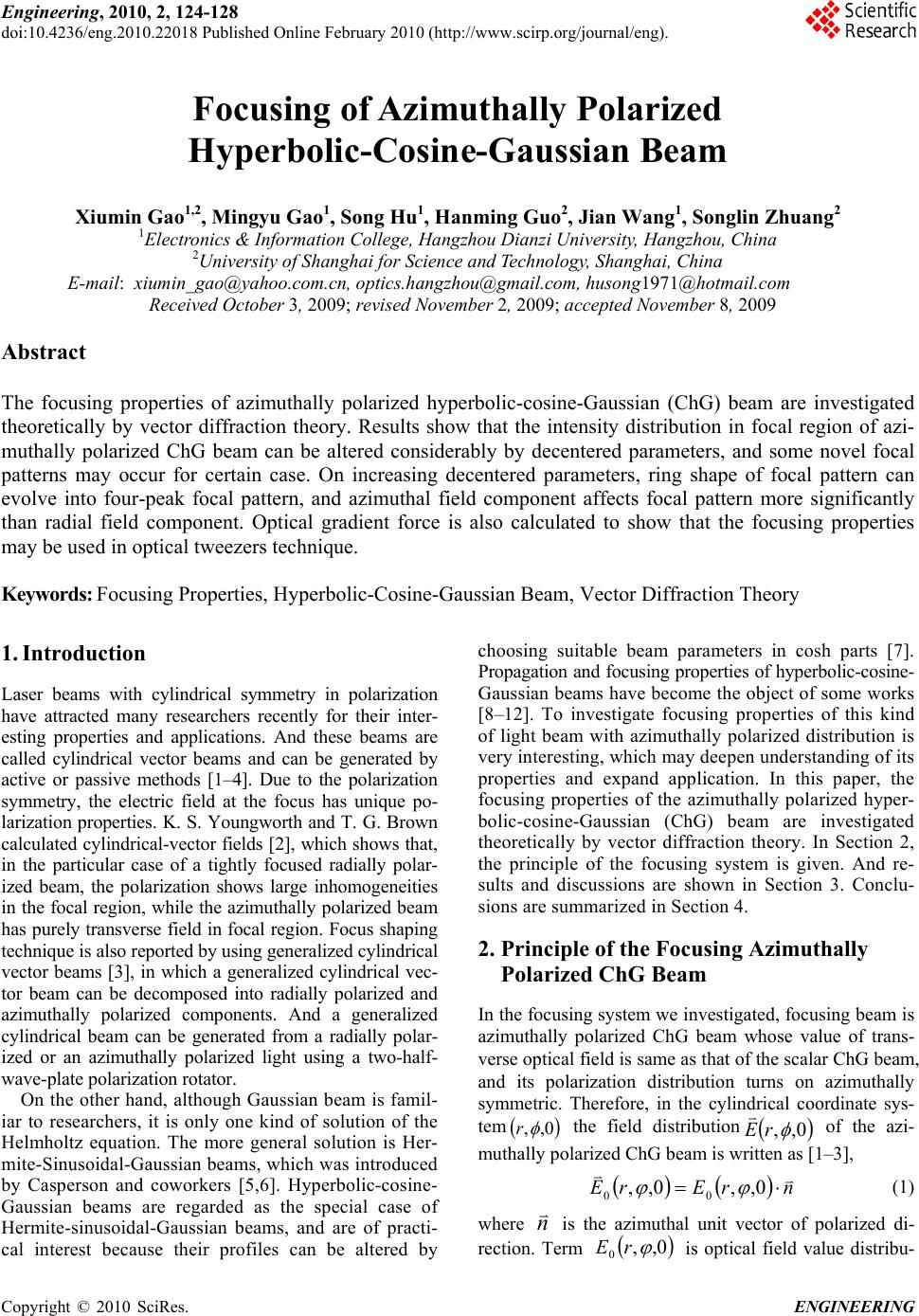 Engineering, 2010, 2, 124-128 doi:10.4236/eng.2010.22018 Published Online February 2010 (http://www.scirp.org/journal/eng). Copyright © 2010 SciRes. ENGINEERING Focusing of Azimuthally Polarized Hyperbolic-Cosine-Gaussian Beam Xiumin Gao1,2, Mingyu Gao1, Song Hu1, Hanming Guo2, Jian Wang1, Songlin Zhuang2 1Electronics & Information College, Hangzhou Dianzi University, Hangzhou, China 2University of Shanghai for Science and Technology, Shanghai, China E-mail: xiumin_gao@yahoo.com.cn, optics.hangzhou@gmail.com, husong1971@hotmail.com Received October 3, 2009; revised November 2, 2009; accepted November 8, 2009 Abstract The focusing properties of azimuthally polarized hyperbolic-cosine-Gaussian (ChG) beam are investigated theoretically by vector diffraction theory. Results show that the intensity distribution in focal region of azi- muthally polarized ChG beam can be altered considerably by decentered parameters, and some novel focal patterns may occur for certain case. On increasing decentered parameters, ring shape of focal pattern can evolve into four-peak focal pattern, and azimuthal field component affects focal pattern more significantly than radial field component. Optical gradient force is also calculated to show that the focusing properties may be used in optical tweezers technique. Keywords: Focusing Properties, Hyperbolic-Cosine-Gaussian Beam, Vector Diffraction Theory 1. Introduction Laser beams with cylindrical symmetry in polarization have attracted many researchers recently for their inter- esting properties and applications. And these beams are called cylindrical vector beams and can be generated by active or passive methods [1–4]. Due to the polarization symmetry, the electric field at the focus has unique po- larization properties. K. S. Youngworth and T. G. Brown calculated cylindrical-vector fields [2], which shows that, in the particular case of a tightly focused radially polar- ized beam, the polarization shows large inhomogeneities in the focal region, while the azimuthally polarized beam has purely transverse field in focal region. Focus shaping technique is also reported by using generalized cylindrical vector beams [3], in which a generalized cylindrical vec- tor beam can be decomposed into radially polarized and azimuthally polarized components. And a generalized cylindrical beam can be generated from a radially polar- ized or an azimuthally polarized light using a two-half- wave-plate polarization rotator. On the other hand, although Gaussian beam is famil- iar to researchers, it is only one kind of solution of the Helmholtz equation. The more general solution is Her- mite-Sinusoidal-Gaussian beams, which was introduced by Casperson and coworkers [5,6]. Hyperbolic-cosine- Gaussian beams are regarded as the special case of Hermite-sinusoidal-Gaussian beams, and are of practi- cal interest because their profiles can be altered by choosing suitable beam parameters in cosh parts [7]. Propagation and focusing properties of hyperbolic-cosine- Gaussian beams have become the object of some works [8–12]. To investigate focusing properties of this kind of light beam with azimuthally polarized distribution is very interesting, which may deepen understanding of its properties and expand application. In this paper, the focusing properties of the azimuthally polarized hyper- bolic-cosine-Gaussian (ChG) beam are investigated theoretically by vector diffraction theory. In Section 2, the principle of the focusing system is given. And re- sults and discussions are shown in Section 3. Conclu- sions are summarized in Section 4. 2. Principle of the Focusing Azimuthally Polarized ChG Beam In the focusing system we investigated, focusing beam is azimuthally polarized ChG beam whose value of trans- verse optical field is same as that of the scalar ChG beam, and its polarization distribution turns on azimuthally symmetric. Therefore, in the cylindrical coordinate sys- tem 0,, r the field distribution 0,, rE of the azi- muthally polarized ChG beam is written as [1–3], nrErE 0,,0,, 00 (1) where n is the azimuthal unit vector of polarized di- rection. Term 0,, 0 rE is optical field value distribu- 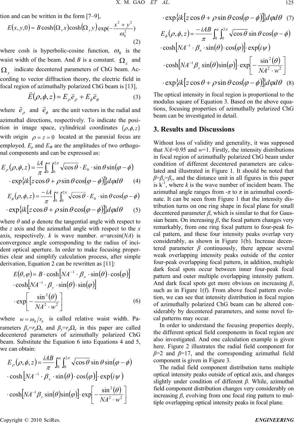 X. M. GAO ET AL.125 tion and can be written in the form [7–9], yxByxE yx coshcosh0,, )exp( 2 0 22 yx (2) where cosh is hyperbolic-cosine function, 0 is the waist width of the beam. And B is a constant. x and indicate decentered parameters of ChG beam. Ac- cording to vector diffraction theory, the electric field in focal region of azimuthally polarized ChG beam is [13], y eEeEzE ,, (3) where e and e are the unit vectors in the radial and azimuthal directions, respectively. To indicate the posi- tion in image space, cylindrical coordinates z,, with origin 0 z located at the paraxial focus are employed. Eρ and EΦ are the amplitudes of two orthogo- nal components and can be expressed as: 0 2 00sinsincos,, E iA zE ddzik cossincosexp (4) 0 2 00cossincos,, E iA zE ddzik cossincosexp (5) where θ and φ denote the tangential angle with respect to the z axis and the azimuthal angle with respect to the x axis, respectively. k is wave number. α=arcsi n(NA) is convergence angle corresponding to the radius of inci- dent optical aperture. In order to make focusing proper- ties clear and simplify calculation process, after simple derivation, Equation 2 can be rewritten as [11]: ,E cossincosh 1 x NAB sinsincosh 1 y NA 22 2 sin exp wNA (6) where 00 rw is called relative waist width. Pa- rameters βx=rpΩx and βy=rpΩy in this paper are called decentered parameters of azimuthally polarized ChG beam. Substitute the Equation 6 into Equations 4 and 5, we can obtain: 0 2 0sinsincos,, iAB zE iNA xexpcossincosh 1 22 2 1sin expsinsincosh wNA NA y ddzik cossincosexp (7) 0 2 0cossincos,, iAB zE iNA xexpcossincosh 1 22 2 1sin expsinsincosh wNA NA y ddzik cossincosexp (8) The optical intensity in focal region is proportional to the modulus square of Equation 3. Based on the above equa- tions, focusing properties of azimuthally polarized ChG beam can be investigated in detail. 3. Results and Discussions Without loss of validity and generality, it was supposed that NA=0.95 and w=1. Firstly, the intensity distributions in focal region of azimuthally polarized ChG beam under condition of different decentered parameters are calcu- lated and illustrated in Figure 1. It should be noted that β=βx=βy, and the distance unit in all figures in this paper is k-1, where k is the wave number of incident beam. The azimuthal angle ranges from -π to π in azimuthal coordi- nate. It can be seen from Figure 1 that the intensity dis- tribution turns on one ring shape in focal plane for small decentered parameter β, which is similar to that for Gaus- sian beam. On increasing β, the focal pattern changes very remarkably, from one ring focal pattern to four-peak fo- cal pattern, and these four intensity peaks overlap very considerably, as shown in Figure 1(b). Increase decen- tered parameter β continuously, there appear several weak overlapping intensity peaks outside of the center four-peak overlapping focal pattern, in addition, multiple dark focal spots occur between inner four-peak focal pattern and outer multiple overlapping intensity pattern. And dark focal spots get more obvious on increasing β, such as in Figure 1(f). From above focal pattern evolu- tion, we can see that intensity distribution in focal region of azimuthally polarized ChG beam can be altered con- siderably by decentered parameters, and some novel fo- cal patterns may occur. In order to understand the focusing properties deeply, the different optical field components in focal region are also investigated. And one calculation example is given here. Figure 2 illustrates the radial field component for β=2 and β=17, and the corresponding azimuthal field component is given in Figure 3. The radial field component distribution turns multiple optical intensity peaks outside of optical axis, and changes slightly under condition of different β. While, azimuthal field component distribution changes very considerably on increasing β, evolving from one focal ring pattern to mul- tiple overlapping optical intensity peaks in focal plane. Copyright © 2010 SciRes. ENGINEERING  X. M. GAO ET AL. 126 (a) (b) (c) (d) (e) (f) Figure 1. Intensity distributions in focal region for (a) β=2, (b) β=5, (c) β=8, (d) β=11, (e) β=14, and (f) β=17, respectively. By comparing Figures 2 and 3 with Figure 1, it can be seen that azimuthal field component distribution is very similar to total focal pattern. Therefore, azimuthal field component affects focal pattern more significantly than radial field component, namely, azimuthal field compo- nent decides optical intensity distribution in focal region of the azimuthally polarized ChG beam. Now, the possible application of focusing of azimuth- ally polarized ChG beam is discussed. Optical tweezers have been increasingly valuable tool for research and accelerated many major advances in numerous areas of science [14–17]. In optical tweezers system, it is usually deemed that the forces exerted on the particles in light field include two kinds of forces, one is the gradient force, which is proportional to the intensity gradient; the other is the scattering force, which is proportional to the optical intensity [16]. So, the tunable focal pattern pre- dicts that the optical trap may be controllable. The gra- dient force trap is necessary condition for constructing the optical trap and can be expressed as [16] 2 2 2 32 ,, 2 1 2zE m m rn Fb grad (9) where r is the radius of trapped particles, nb is the refrac- tion index of the surrounding medium, and , the rela- tive index of refraction, equals to the ratio of the refrac- tion index of the particle np to the refraction index of the m Co pyright © 2010 SciRes. ENGINEERING 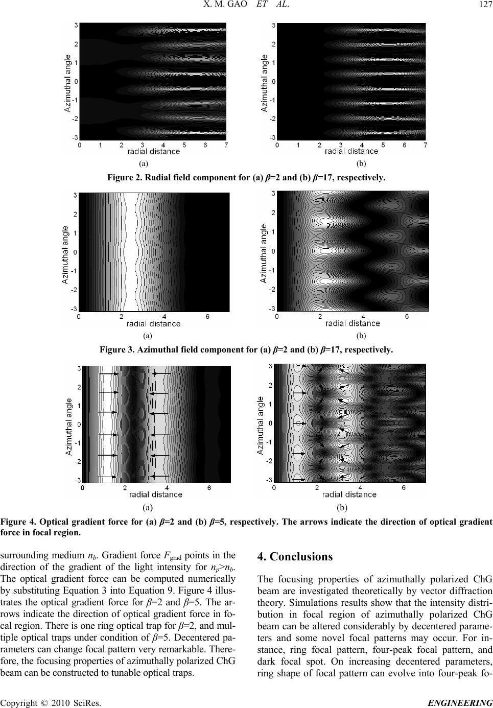 X. M. GAO ET AL. 127 (a) (b) Figure 2. Radial field component for (a) β=2 and (b) β=17, respectively. (a) (b) Figure 3. Azimuthal field component for (a) β=2 and (b) β=17, respectively. (a) (b) Figure 4. Optical gradient force for (a) β=2 and (b) β=5, respectively. The arrows indicate the direction of optical gradient force in focal region. surrounding medium nb. Gradient force Fgrad points in the direction of the gradient of the light intensity for np>nb. The optical gradient force can be computed numerically by substituting Equation 3 into Equation 9. Figure 4 illus- trates the optical gradient force for β=2 and β=5. The ar- rows indicate the direction of optical gradient force in fo- cal region. There is one ring optical trap for β=2, and mul- tiple optical traps under condition of β=5. Decentered pa- rameters can change focal pattern very remarkable. There- fore, the focusing properties of azimuthally polarized ChG beam can be constructed to tunable optical traps. 4. Conclusions The focusing properties of azimuthally polarized ChG beam are investigated theoretically by vector diffraction theory. Simulations results show that the intensity distri- bution in focal region of azimuthally polarized ChG beam can be altered considerably by decentered parame- ters and some novel focal patterns may occur. For in- stance, ring focal pattern, four-peak focal pattern, and dark focal spot. On increasing decentered parameters, ring shape of focal pattern can evolve into four-peak fo- Co pyright © 2010 SciRes. ENGINEERING  X. M. GAO ET AL. Copyright © 2010 SciRes. ENGINEERING 128 cal pattern, which may be used to construct tunable opti- cal tweezers. In addition, azimuthal field component af- fects focal pattern more significantly than radial field component. 5. Acknowledgments This work was supported by National Basic Research Program of China (2005CB724304), National Natural Science Foundation of China (60708002, 60807007, 60871088, 60778022), China Postdoctoral Science Foun- dation (20080430086), Shanghai Postdoctoral Science Foundation of China (08R214141), and Shanghai Lead- ing Academic Discipline Project (S30502). 6 . References [1] Q. Zhan, “Cylindrical vector beams: From mathematical concepts to applications,” Advances in Optics and Photonics, Vol. 1, pp. 1–57, 2009. [2] K. S. Youngworth and T. G. Brown, “Focusing of high numerical aperture cylindrical-vector beams,” Optics Ex- press, Vol. 7, pp. 77–87, 2000. [3] X. Gao, J. Wang, H. Gu, and W. Xu, “Focusing properties of concentric piecewise cylindrical vector beam,” Optik, Vol. 118, pp. 257–265, 2007. [4] G. Zhou, Y. Ni, and Z. Zhang, “Analytical vectorial structure of non-paraxial nonsymmetrical vector Gaussian beam in the far field,” Optics Communications, Vol. 272, pp. 32–39, 2007. [5] L. W. Casperson, D. G. Hall, and A. A. Tovar, “Sinusoidal- Gaussian beams in complex optical systems,” Journal of Optical Society of America A, Vol. 14, pp. 3341–3348, 1997. [6] L. W. Casperson and A. A. Tovar, “Hermite-sinusoidal- Gaussian beams in complex optical systems,” Journal of Optical Society of America A, Vol. 15, pp. 954–961, 1998. [7] X. Du and D. Zhao, “Elliptical cosh-Gaussian beams,” Optics Communications, Vol. 265, pp. 418–424, 2006. [8] Z. Hricha and A. Belafhal, “Focusing properties and focal shift in hyperbolic-cosine-Gaussian beams,” Optics Communications, Vol. 253, pp. 242–249, 2005. [9] B. Lu and S. Luo, “Beam propagation factor of hard-edge diffracted cosh-Gaussian beams,” Optics Communications, Vol. 178, pp. 275–281, 2000. [10] B. Lu, H. Ma, and B. Zhang, “Propagation properties of cosh-Gaussian beams,” Optics Communications, Vol. 164, pp. 165–170, 1999. [11] X. Gao, “Focusing properties of the hyperbolic-cosine- Gaussian beam induced by phase plate,” Physics Letters A, Vol. 360, pp. 330–335, 2006. [12] X. Gao and J. Li, “Focal shift of apodized tunrcated hyperbolic-cosine-Gaussian beam,” Optics Communications, Vol. 273, pp. 21–27, 2007. [13] S. Sato and Y. Kozawa, “Hollow vortex beams,” Journal of Optical Society of America A, Vol. 26, pp. 142–146, 2009. [14] M. P. MacDonald, L. Paterson, K. V. Sepulveda, J. Arlt, W. Sibbett, and K. Dholakia, “Creation and manipulation of three-dimensional optically trapped structures,” Science, Vol. 296, pp. 1101–1103, 2002. [15] D. G. Grier, “A revolution in optical manipulation,” Nature, Vol. 424, pp. 810–816, 2003. [16] V. Garces-Chaves, D. McGloin, H. Melville, W. Sibbett, and K. Dholakia, “Simultaneous micromanipulation in multiple planes using a self reconstructing light beam,” Nature, Vol. 419, pp. 145–147, 2002. [17] K. Visscher and G. J. Brakenhoff, “Theoretical study of optically induced forces on spherical particles in a single beam trap I: Rayleigh scatterers,” Optik, Vol. 89, pp. 174–180, 1992. |