Journal of Electromagnetic Analysis and Applications
Vol. 1 No. 4 (2009) , Article ID: 1124 , 5 pages DOI:10.4236/jemaa.2009.14043
Design of a Control Device for Synthetic Making Test Based on Pre-Arcing Current Detection and Phase Control
![]()
1Department of Electrical and Electronics Engineering, Dalian University of Technology, Dalian, China; 2School of Mechanical of Electrical Engineering, Guilin University of Electronic Technology, Guilin, China.
Email: zhouzhengyang123@sina.com
Received July 22nd, 2009; revised August 12th, 2009; accepted August 20th, 2009.
Keywords: Synthetic Making Test, Pre-Arcing Current, Phase Control
ABSTRACT
The synthetic making test has been widely used in evaluating the break ability of high-voltage circuit breaker. However, the test research and application are still inadequate, especially in the condition of rated voltage. According to the realistic conditions of test stations in China, a control device based on pre-arcing current detection and phase control is proposed in this paper. A sample of the control device made up of DSP TMS320LF2407A is fabricated, in which the CPLD MAX7064 is used to transmit signals for EMC design. It can be applied in full voltage synthetic making test at a level of 126kV/63kA. The test results show that, it is accurate to control the making phase of the applied voltage, whether the closing is demanded at voltage peak or zero.
1. Introduction
It is well recognized that the verification of the making ability of circuit breakers is an integral part of the certification procedure. A circuit breaker rated 145kV/40kA can be tested three-phase at full voltage and current, which is the highest rating that can be carried out with direct three-phase short-circuit power at KEMA highpower laboratory in Holland [1]. However, in many cases direct making test exceeds the available power of the test laboratories. So the synthetic test circuit has been put into service and it is widely accepted at present. The test basic rules and applied conditions have been discussed at CIGRE in 1960’s and 1970’s [2,3]. According to the latest IEC60427 and China National Standard GB1984- 2003, for the circuit breaker whose pre-arcing is obvious, it is necessary to test not only the rated short circuit close ability at reduced applied voltage, but also the close and open ability with maximum pre-arcing at standard applied voltage, which can prove the loading ability of circuit breaker when the pre-arcing occurs at applied voltage peak, leading to a symmetrical closing current [4,5].
Synthetic making test of high-voltage circuit breakers at full voltage is a close test at rated applied voltage. It is reported that the KEMA laboratory can do three-phase synthetic making test at 245kV/63kA [1], and the ABB Company at 362kV [6]. On the basis of realistic conditions of high power laboratories in China, a control device for the synthetic making test at full voltage based on pre-arcing current detection and phase control is proposed in this paper. A test circuit and its control system made up of DSP and CPLD are set up. The whole system has been applied in synthetic making test at a full voltage of 126kV/63kA.
2. Experiment Setup
The experimental circuit of synthetic making test is shown in Figure 1, with one circuit supplying the full rated voltage to initiate pre-strike and the second circuit to supply the short circuit current succeeding the prestrike at reduced voltage.
In Figure 1 U1 and U2 mean the current and voltage source respectively. QFt is the switching device under test. The unit of Sa and CH constitutes the fast making switch, which is made up of triggered vacuum switch (TVS) and fast vacuum circuit breaker (FVCB) with permanent magnetic actuator [7]. Parallel-connected TVS and FVCB make up the basic optic-controlled mod-
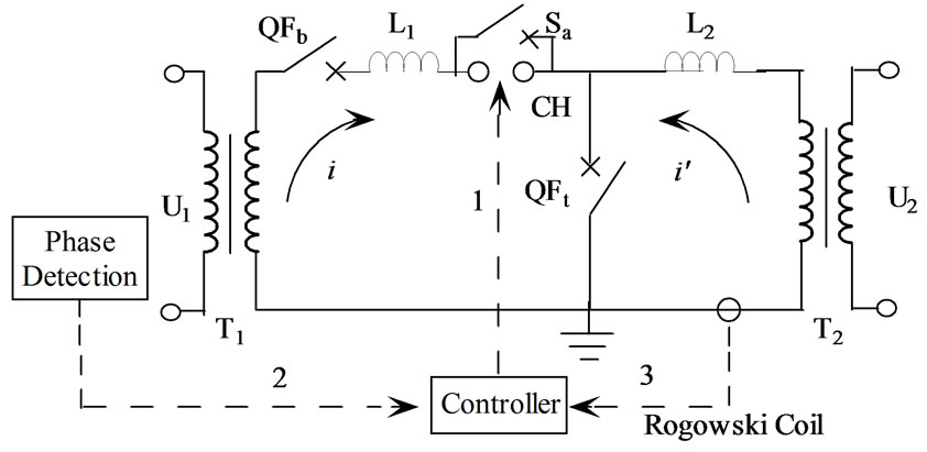
Figure 1. Circuit for synthetic making test
ule. And the arranging of basic modules in series can increase the withstand voltage. The closing commands of Sa and CH are sent out simultaneously. QFb is connected to the current source rapidly (in several microseconds) and accurately through Sa when pre-strike occurs in QFt. CH (FVCB) turns on subsequently and the making current will shift to this branch, to reduce and protect the wear of Sa (TVS). The Rogowski Coil is used to detect the pre-arcing current.
The aim of design is to control the making phase of the applied voltage, whether the closing is demanded at voltage peak or zero. From the Controller in Figure 1, we can see that the control strategy for synthetic making test lies on three aspects, i.e., the fast making device, pre-arcing current detection and phase control. Firstly, the detected information of pre-arcing current and voltage/current phase are input to the controller. Secondly, the controller calculates the delay time. Lastly, controller outputs a signal to the fast making switch, making it to turn on at the voltage peak or zero. The fast making switch has been discussed in the previous paragraph, and the other two aspects will be expanded in Section 3 and Section 4.
3. Pre-Arcing Current Detection
3.1 Entire Structure
The frame of pre-arcing current detection is shown as Figure 2. It is the time when the pre-arcing appears to close the fast making device. So it is important to detect pre-arcing current fleetly and accurately.
3.2 Rogowski Coil
There are three ways to detect the pulse high current: divider, optics device and coil [8]. Because the pulse current can reach a level of several ten thousands to even millions amperes, it is difficult for a divider to work effectively, and the optics device is complex. The coil is suited to detect the pulse high current, which is measured through the voltage in the coil induced by the aim current [8]. The detected current doesn’t flow through the coil, so it is isolated between the detection system and the tested main loop, which is helpful for safe request and EMC design. The principle of Rogowski coil shows that the last result of aim current is in direct ratio to the turn number of coil (N), and in inverse ratio to the signal resistant (R) which is connected to the output of coil [9]. It is shown as:
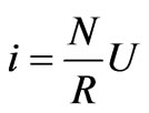 (1)
(1)
U is the voltage of tested signal. In this paper, the N adopted is 1000, and R is 0.019Ω. So the current detected can be measured as:
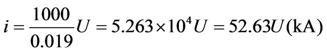 (2)
(2)
In order to get the properties of coil, a standard divider is used to check the output of coil. The resistant value of standard divider is 600μΩ. The tested current is restrained from 8kA to 15kA, due to the measurement range of divider. A typical wave of tested results is shown as Figure 3, where CH1 is the signal wave of Rogowski Coil, and the CH2 is the signal wave of divider. The multiple results are stored in Table 1. The compare of these results shows that, the Rogowski Coil is credible.
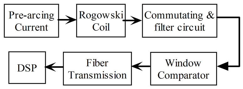
Figure 2. Frame of pre-arcing current detection
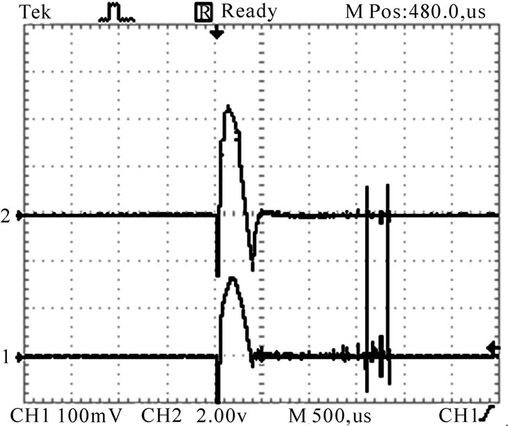
Figure 3. Tested result of Rogowski coil
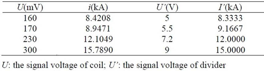
Table 1. Multiple tested results of Rogowski coil
3.3 Precise Commutating and Filter Circuit
The high-speed operational amplifier LM318 is adopted in the circuit, with typical signal bandwidth of 15MHz, and inversion frequency of 70-150V/μs. It will be of benefit to reduce the hardware delay of detecting the pre-arcing current signal and leave enough time for DSP processing. The precise commutating and filter circuit is shown in Figure 4.
The output of filter circuit makes the input signal of hyper speed window comparator, which is made up of hyper speed comparator TL3016 of TI Company. The threshold value of window comparator is the set range of pre-arcing current. When the transient value of signal meets the set range, the optical fiber transmission system will send an interrupt to the DSP. That is the total process of pre-arcing current detection.
4. Phase Control
4.1 Control Method
The closing command of device is random in power system. To simulate the actual operation of circuit breaker, distinction is made in the standards between two extreme cases: one condition is making at the voltage peak, leading to a symmetrical short-circuit current and the longest pre-strike; the other condition is making at the voltage zero, without pre-arcing, leading to a fully asymmetrical short-circuit current [4,5].
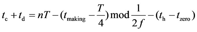
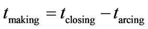
Figure 5 takes the condition of making at voltage peak for example to illustrate the control method. The processor samples the applied voltage in real time, and once the zero of voltage is detected the timer begins to count until the random closing command comes (th). If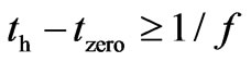 , the timer resets and counts up from 0 again, where the f denotes the frequency of applied voltage. Or else, the phase control closing command will be sent after delay of tc+td, where tc is operation and calculation time of DSP, and td is the waiting time to sent the phase control closing command. And tmaking later, prestrike occurs between the approaching electrodes of switch to be tested. At this time the fast making device acts, so the short circuit current flows through the tested switch. tc+td can be calculated by the DSP from the following Equations [10]:
 (3)
(3)
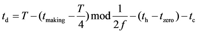 (4)
(4)
 (5)
(5)
Because the timer will reset if , the value of n can be testified as 1 in Equation (3). Mod is the remainder. tclosing and tarcing are the closing and pre-arcing time of the tested switch respectively, which can be known before the test.
4.2 Hardware Configuration
The hardware configuration of the system is shown in Figure 6. The DSP TMS320Lf2407A is adopted as the CPU, which offers up to 16 channels 10-bit ADC, CAN 2.0B module, SCI and Watchdog Timer Module, etc. The DSP takes the pre-strike current and random closing command as its input signals, meanwhile detects the phases of current and voltage in real time.
The data and signals transmitted in the system are all in the optical fibers. The structure of control signals transmission system with fiber is shown in Figure 7,
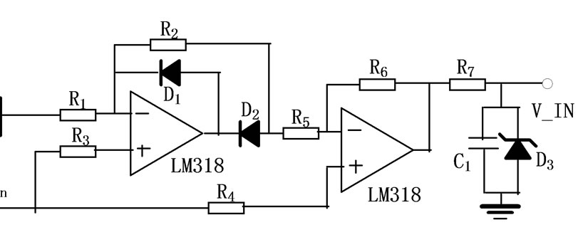
Figure 4. Precise commutating and filter circuit
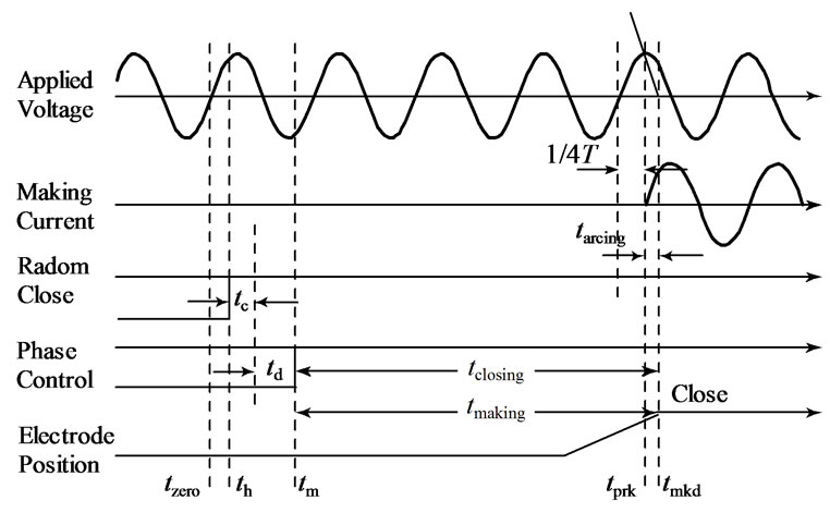
Figure 5. Phase control closing time sequence
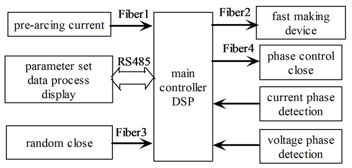
Figure 6. Diagram of the control system
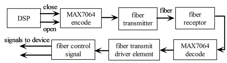
Figure 7. Structure of control signals transmission
where the MAX7064 is the CPLD made by Altera Company. Two channels of control signals are sent by DSP, i.e. closing signal and opening signal for Sa and CH. When the closing signal jumps to 1 while opening signal keeps 0, MAX7064 will send closing control code 1010 to the fiber. Otherwise the opening signal jumps to 1 while closing signal keeps 0, MAX7064 will send opening control code 1001 to the fiber. Thus the EMC design of the system can be improved distinctly especially in the high power laboratory environment.
4.3 Software Design
The software flow chart of main program in DSP is shown in Figure 8.
The random close command and the phase control close command are the close instructions for the switching device to be tested.
4.4 Discussions
It is necessary to control the making phase of the applied voltage accurately, whether the closing is demanded at voltage peak or zero. There are many factors that influence the test accuracy and success rate, such as the variations of operating times and pre-strike characters of the switching device to be tested. According to the standards [4,5], the time from the point of pre-strike to the voltage peak should be limited in 1.5ms, i.e. the pre-strike occurs at the phase of 90˚±27˚ for power current.
The system has been applied in the full voltage synthetic making test at a level of 126kV/63kA.The test result is shown as Figure 9 and Figure 10. The waveforms presented in Figure 9 are the results of making at voltage peak. It is evident that the percent of DC component of the tested making current is low, i.e., symmetrical short-circuit current. The waveforms of Figure 10 are the results of making at voltage zero, and the percent of DC component is high, i.e., asymmetry short-circuit current.
The phase control is accurate at the voltage peak, because the pre-strike characters of tested switching device are stable and no pre-strike occurs before the voltage peak. From abundant experiments, it is proved that the typical deviation of time from the point of pre-strike to the voltage peak is about 800μs, and it is limited in 1.5ms. Another way, the fast making switch of current source is controlled not to turn on if the deviation is much large, which can reduce the failure of making (see the phase satisfied pre-strike current of software flow chart in Figure 8).
5. Conclusions
1) A control device for synthetic making test at full voltage based on pre-arcing current detection and phase control is proposed in this paper.
2) Rogowski coil is adopted to detect the pre-arcing current of synthetic making test, and DSP is used as main controller to complete the phase control and data proce-
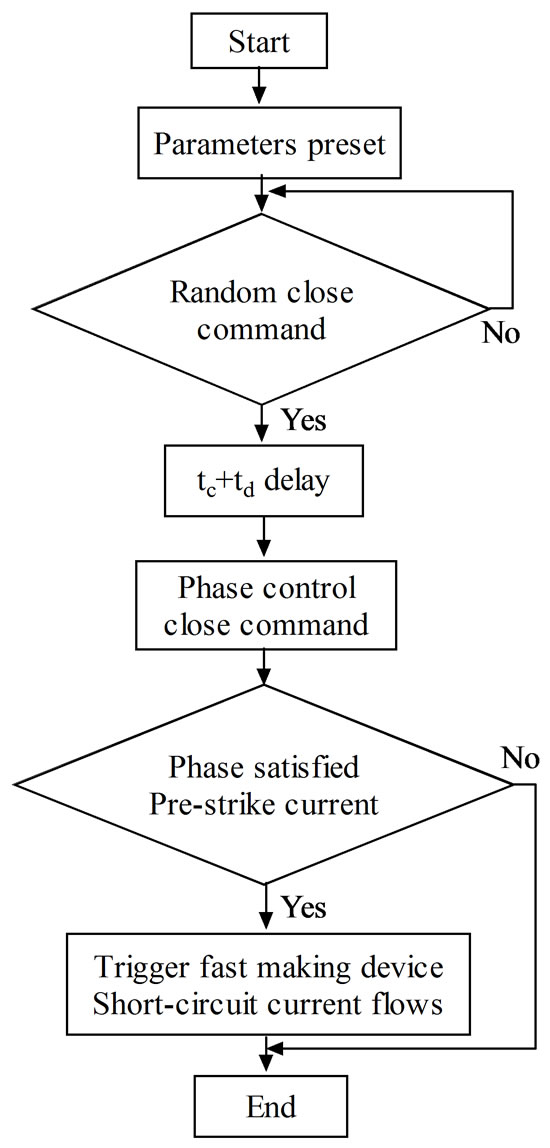
Figure 8. Software flow chart of main program
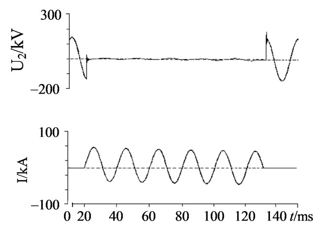
Figure 9. Test result of voltage peak
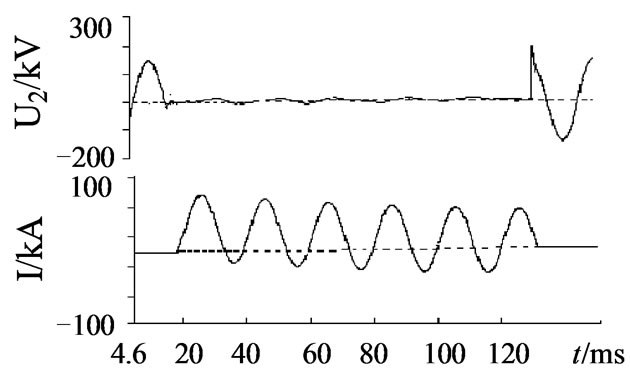
Figure 10. Test result of voltage zero
ssing.
3) The system has been applied in the full voltage synthetic making test at a level of 126kV/63kA. It is accurate to control the making phase of applied voltage, whether the closing is demanded at voltage peak or zero.
6. Acknowledgment
This work is supported partly by National Natural Science Foundation of China (No. 50507001).
REFERENCES
- R. P. P. Smeets and W. A. van der Linden, “Verification of the short-circuit current making capability of highvoltage switching devices,” IEEE Transactions on Power delivery, Vol. 16, No. 4, pp. 611–618, 2001.
- Discussion Group 13, “Synthetic circuit for making tests,” CIGRE Conference, pp. 444–445, 1966.
- CIGRE WG 13.04, “Requirements for testing making performance of high-voltage circuit breakers at reduced applied voltage,” Electra, Vol. 163, No. 6, pp. 27–33. 1979.
- IEC60427, “Synthetic testing of high-voltage alternatingcurrent circuit breakers,” 2000
- GB 1984–2003, “High-voltage alternating-current circuitbreakers.”
- B L Sheng, “Design consideration of weil-dobke synthetic testing circuit for the interrupting testing of HV AC breakers,” IEEE Power Engineering Society Winter Meeting, Vol. 1, No. 28, pp. 295–299, 2001.
- X. M. Fan, J. Y. Zou, and J. Y. Cong, “Research on the measurement and controlling system for synthetic making test of high-voltage circuit breakers at full voltage,” 6th International Symposium on Test and Measurement, Vol. 3, pp. 2709–2712, 2005.
- X. P. Li, C. Zhao, L. Y. Li, J. Y. Zhou and T. Meng, “The test system of pulse high current in the reconnection electromagnetic gun,” 6th International Symposium on Test and Measurement, Vol. 3, pp. 2847–2850, 2005.
- J. Y. Zou, X. Y. Duan, and T. Zhang, “The simulating calculation and experimental research of Rogowski coil for current measurement,” Transactions of China Electrotechnical Society, Vol. 16, No. 1, pp. 82–84, Feburay 2001.
- X. M. Fan, J. Y. Zou, E. Y. Dong, and J. Y. Cong, “Control strategy of synthetic making test for high voltage circuit breakers at full voltage and its realization,” Power system technology, Vol. 29, No. 17, pp. 8–13, 2005.