Int'l J. of Communications, Network and System Sciences
Vol.3 No.2(2010), Article ID:1278,4 pages DOI:10.4236/ijcns.2010.32029
Geometry Aspects and Experimental Results of a Printed Dipole Antenna
1Physics Department, University of Ioannina, Panepistimioupolis, Ioannina, Greece
2Siemens Enterprise Communications, Enterprise Products Development, Athens, Greece
E-mail: kvotis@grads.uoi.gr, basilios.christofilakis@siemens-enterprise.com, kostarakis@uoi.gr
Received November 2, 2009; revised December 21, 2009; accepted December 27, 2009
Keywords: Printed Dipole, Scattering Parameters, Radiation Pattern
Abstract
Detail experimental measurements of a 2.4 GHz printed dipole antenna for wireless communication systems is presented and discussed. A group of printed dipoles with integrated balun have been designed and constructed on a dielectric substrate. This paper is based on modifications of the known printed dipole architecture. The corresponding printed dipole antennas have differences on their forms that are provided by two essential geometry parameters. The first parameter l is related to the bend on microstrip line that feeds the dipole and the second w corresponds to the form of the dipole’s gap. The impact of these parameters on reflection coefficient and radiation pattern of antenna has been investigated. The corresponding measured results indicate that the return loss and radiation pattern of a printed dipole antenna are independent of the w parameter. Instead, variations in the value of the l parameter in the dipole’s structure affect the form of the corresponding return loss. These observations are very important and provide interesting considerations on affecting design and construction of antenna elements at frequency range of 2.4 GHz.
1. Introduction
Modern wireless communications offer higher bit rates and efficient quality of services. The majority of the equipment used today introduces requirements for better performance and lower cost. Antennas with quite small sizes, low profiles and versatile features represent interesting solutions that provide modern wireless applications. The printed dipole antenna with integrated balun is widely used as a radiation element on communication systems because of its omni-directional features, narrowband character and simple structure [1–4]. This type of antenna because of its small size can be integrated on the same PCB with other electronics circuits and devices. For the same reason, it can also be used as element on antenna array architecture. The last feature is very interesting and attractive in MIMO modern wireless systems. This printed dipole architecture offers versatile characteristics for design and implementation of antenna arrays on both ends of a MIMO wireless system.
In the present paper, we will study and discuss the effect of the variation of the two geometrical parameters (l, w) of the printed dipole antenna structure. The first corresponds to a discontinuity on microstrip line of printed dipole and the second is related to the discontinuity in the gap. Details of structure concept and design process are presented in Section 2; the experimental results for return loss and radiation pattern for each of the printed dipoles are presented and discussed in Section 3. The paper concludes in Section 4.
2. Design and Structure Aspects
As mentioned above, the proposed analysis is based on geometrical characteristics of a prototype printed dipole antenna with integrated balun. This kind of printed dipole antenna is considered for use in many applications [1–3]. In our study the geometrical parameters of the printed dipole antenna were modified to achieve better performance in the frequency range of 2.4 GHz. This modified design and the corresponding parameters are shown in Figure 1 while the values summarized in Table 1.
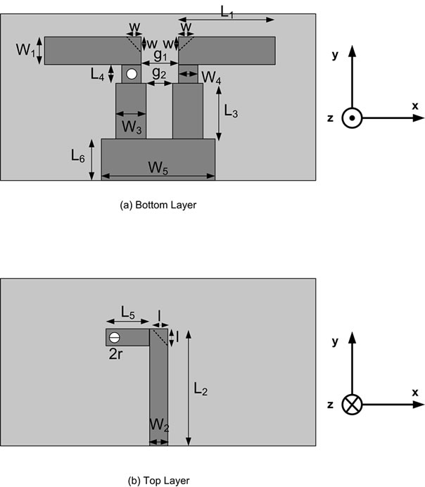
Figure 1. Geometry of printed dipole.
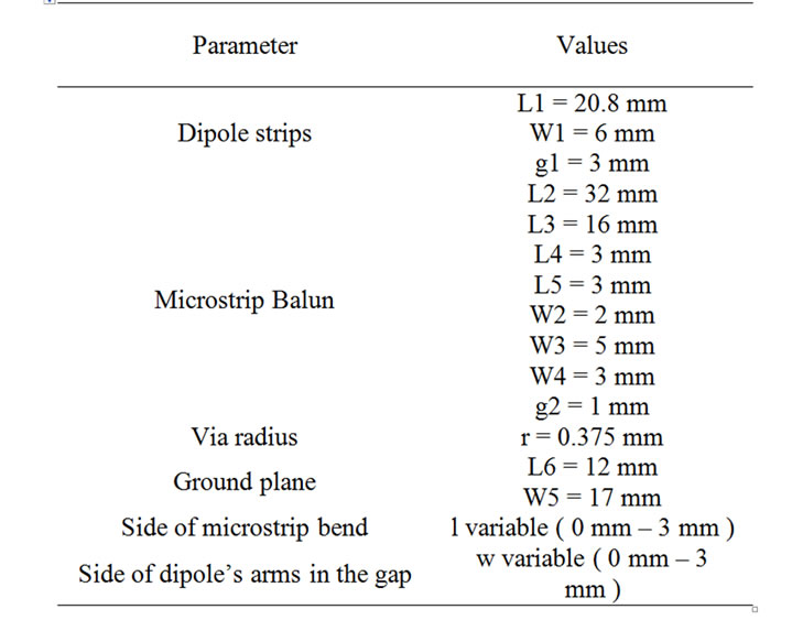
Table 1. Printed dipole dimensions.
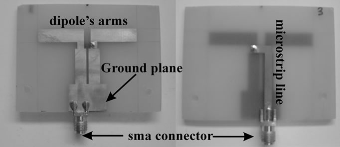
Figure 2. Prototype printed dipole antenna: Top Layer (left) –Bottom Layer (right).
An Fr-4 substrate with thickness of 1.5 mm and permittivity εr =4.4 has been used for the fabrication of the dipoles. Figure 2 shows the top and bottom layer for the one of them. It also presents the dipole’s arms and gap, the balun, the ground plane and the microstrip line that interface the dipole with the coaxial feed line via sma connector.
From this Figure, we can also see the right angle at the microstrip line and the other two right angles at the dipole’s gap. It is known that the presence of right angles in conductors cause discontinuities that leads to degradation in circuit performance [5]. Microwave theory suggests that these angles introduce parasitic reactances which can lead to phase and amplitude errors, input and output mismatch and possibly spurious coupling [5–7]. In order to reduce this effect it is proposed to modify these discontinuities directly, by mitering the conductor. Our investigation and the experimental measurements show the effect of mitering these discontinuities. At first, a prototype printed dipole antenna with unaffected geometrical parameters has been designed and constructed. Secondly, we constructed and measured six different printed dipoles. Three of them had w = 0 mm and different l values (1 mm, 2 mm, 3 mm) and the other three dipoles had l = 0 mm and different values of w (1 mm, 2 mm, 3 mm). All these seven dipoles we constructed, the unaffected one and the mitered ones were measured in an anechoic environment. Figures 3 and 4 show a printed dipole for l = 2 mm and w = 0 mm and for l = 0 mm and w = 3 mm, respectively. The aim of this study is to investigate the return loss coefficient and radiation pattern in each of these seven dipole’s forms. The next section discusses the obtained results and presents the significant observations.
3. Results and Discussion
The return loss of the prototype dipole and the six different modified printed dipole antenna we constructed are measured using a Network Analyzer. These results are shown in two Figures. The first (Figure 5) corresponds to l parameter’s variations keeping the w parameter equal to zero. The second (Figure 6) shows the return loss curves where w parameter varies but the l parameter equals to zero. In both figures we can see the return loss curve that belongs to the prototype printed dipole ( l and w equal to 0 mm).
From these curves, it seems that this dipole antenna design has a resonance point at 2.4 GHz with 500 MHz –
Figure 3. Printed dipole antenna for l = 2 mm and w = 0 mm
Top Layer (left) – Bottom Layer (right).
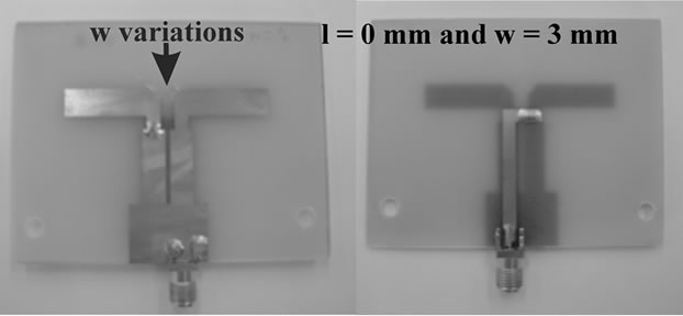
Figure 4. Printed dipole antenna for l = 0 mm and w = 3 mm
Top Layer (left) – Bottom Layer (right).
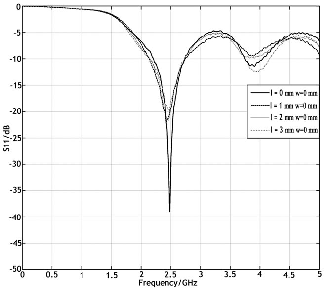
Figure 5. Measured return loss of printed dipole for each value of l parameter and w = 0 mm.
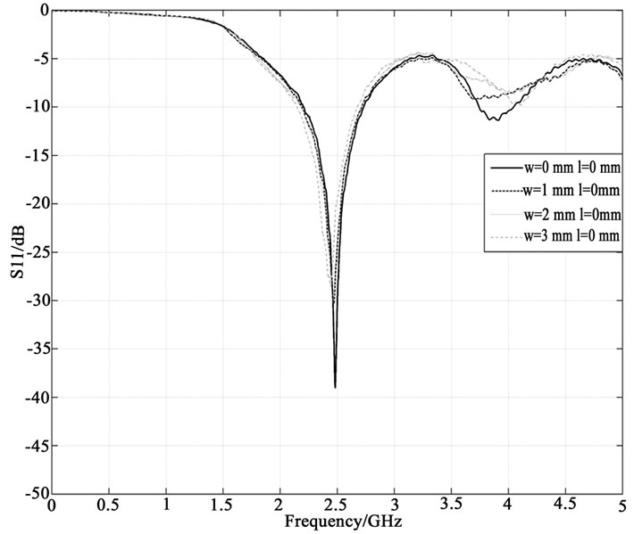
Figure 6. Measured return loss of printed dipole for each value of w parameter and l = 0 mm.
10 dB bandwidth. The last frequency range has center frequency close to 2.4 GHz which is the frequency value that the return loss is minimized. For these frequencies the corresponding values of return loss are smaller or equal to -10 dB. From Figure 5, it is obvious that as the value of l parameter increases, the form of the corresponding return loss curve changes and becomes more flat at the resonance frequency range. On the other hand, the value of w parameter does not affect the form of the return loss curve. Each of these seven forms of printed dipole antenna has quite similar return loss curves and introduces narrowband operation at the frequency range of 2.4 GHz. Moreover, for a wireless application that requires design and construction of many identical printed dipoles, it is recommended to choose l parameter equals to 2 mm and w parameter equals to 0 mm for better performance. As it can be seen from Figure 5 the above investigation ensures that the printed dipole antennas will have quite identical return loss curves and performance as elements in an antenna array configuration.
For deeper analysis on this topic, experimental measurements on radiation pattern of these antennas have also been made. Measurements were carried out in a RF anechoic chamber using a calibrated measuring system. In particular, Figure 7 shows the measurements of radiation pattern in Eplane and in H – plane for each dipole
 (a)
(a)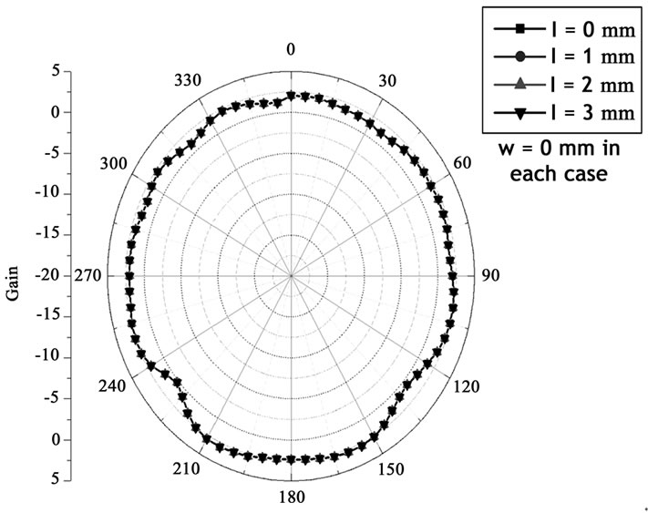 (b)
(b)
Figure 7. Radiation pattern of dipole for each value of l parameter (a) E – plane, (b) H -plane.
 (a)
(a)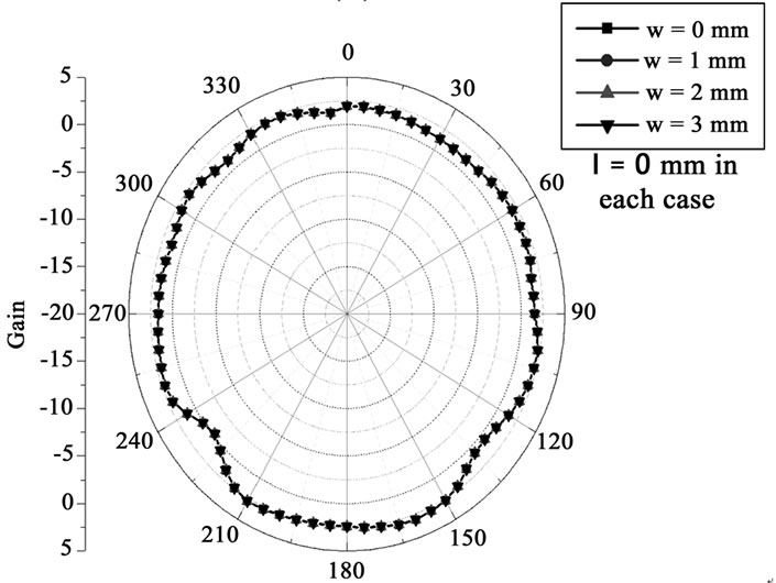 (b)
(b)
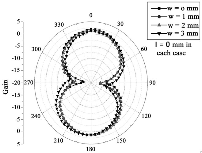
Figure 8. Radiation pattern of dipole for each value of w parameter (a) E – plane, (b) H – plane.
with w parameter equals to 0 mm and l parameter equals to integer values that ranging from 0 mm to 3 mm,. Figure 8 shows the corresponding results for each dipole with l parameter equals to 0 mm and w parameter’s integer values ranging from 0 mm to 3 mm. All these dipole structures introduce radiation characteristics that correspond to a fundamental dipole antenna [6,7]. Each of them has a measured peak gain that equals to quite 2 dBi and introduces omni-directional features. Quite small variations on these curves are on the limits of measurements’ accuracy. For this reason, it can be observed that the radiation characteristics of the printed dipole antenna are not affected by the variations on l and w geometrical parameters. Therefore, the radiation diagrams of them are independent of the l and w parameters.
4. Conclusions
A number of printed dipole antennas with integrated balun are constructed and studied in terms of return loss and radiation pattern. Each of them has a defined form and geometry. Starting from a dipole antenna we mitered the angles introducing the parameters l and w that we varied. Experimental measurements on return loss provide the obtained results. These are quite similar and also introduce a resonance point at frequency range of 2.4 GHz with narrow resonance bandwidth. The form of this resonance range is affected only by the l parameter. The radiation pattern of these dipoles is also investigated. The corresponding radiation diagrams are independent of these geometrical parameters (l, w) and are similar to that of the fundamental dipole. These observations on printed dipole architecture are very crucial for wireless communication engineering and antenna design. This is because they introduce the ability of constructing a group of identical dipoles choosing an appropriate value of l parameter (l =2 mm) with quite identical resonance and radiation characteristics.
5. Acknowledgment
This research project (PENED) is co-financed by E.U.-European Social Fund (80%) and the Greek Ministry of Development-GSRT (20%).
6. References
[1] D. Edward and D. Rees, “A broadband printed dipole with integrated balun,” Microwave J, 1987, pp. 339–344.
[2] N. Michishita, H. Arai, M. Nakano, T. Satoh, and T. Matsuoka, “FDTD analysis for printed dipole antenna with balun,” Asia Pacific Microwave Conference, 2000, pp. 739–742.
[3] G. S. Hilton, C. J. Railton, G. J. Ball, A. L. Hume, and M. Dean, “Finite–difference time–domain analysis of a printed dipole antenna,” 19th Int. IEEE Antennas and Propagation Conference, 1995, pp. 72–75.
[4] H. R. Chuang and L. C. Kuo, “3-D FDTD design analysis of a 2.4 GHz polarization – diversity printed dipole antenna with integrated balun and polarization– switching circuit for wlan and wireless communication application,” IEEE Transactions on Microwave Theory and Techniques, Vol. 51, No. 2, 2003.
[5] D. M. Pozar, Microwave Engineering, Wiley, 1998.
[6] C. A. Balanis, Antenna Theory Analysis and Design, Wiley, 1997.
[7] R. Garg, P. Bhartia, I. Bahl, and A. Ittipiboon, Microstrip Antenna Design Handbook, Artec House, 2001.
NOTES
Identify applicable sponsor/s here. (sponsors)