Circuits and Systems
Vol. 3 No. 1 (2012) , Article ID: 16626 , 4 pages DOI:10.4236/cs.2012.31014
A High Color Rendering Index on Multichip LED Light Source
1Department of Electro-Optics Engineering, National Formosa University, Yunlin County, Chinese Taipei
2Department of Electrical Engineering, National Kaohsiung University of Applied Sciences, Kaohsiung, Chinese Taipei
3Chung Hua-Chin Kong Optoelectronics Co., Ltd., Chung Hwa County, Chinese Taipei
Email: reed@nfu.edu.tw
Received October 4, 2011; revised November 4, 2011; accepted November 12, 2011
Keywords: CRI; PWM Dimming; LED; Flyback Converter
ABSTRACT
Light source carrying a high color rendering index (CRI) finds potential applications in people’s everyday life as well as lighting industry. Combination of multi-wavelength LED light sources with designated direct emission sources can achieve warm-white and cool-white light. A generic design of high CRI multi-wavelength light-emitting-diode (LED) light source, using flyback converter, pulse width modulation (PWM) voltage control, variable resistor, and timer, is proposed. The PWM pulse is for the voltage control of cascade LEDs, while variable resistor manipulates the current flowing through LEDs. A design of dimming drive with cascade-connected electronic switch is also proposed. By adjusting the width of the dimming signal, the average value of forward current pulse can be changed, and therefore the objective, the tuning of the amount of light output, can be fulfilled. The advantage of the proposed design is its short response time.
1. Introduction
The use of LED in lighting applications is overwhelming. The traditional light sources using either incandescent or fluorescent have been shifted to the solid-state’s due to their intrinsic limitations/factors, almost impossible to overcome or to be substituted.
Smart lighting nowadays may be fulfilled by the employment of digitally controlled multi-chip LED systems, belonging to the category of solid state lighting (SSL). SSL offers many advantages such as control of color rendering, chromaticity control, better light quality, and energy-saving; controllability of spectral power distribution, color temperature, temporal modulation, spatial distribution, and polarization properties are feasible [1]. Meanwhile, a trade-off must be made between color rendering and luminous efficacy of the radiation of LEDs. The most significant property of SSL is associated with the development of artificial light sources. Two approaches for white LEDs are phosphor-conversion LED lamp and multi-chip polychromatic LED lamp. The output light emission and forward voltage of LED vary with the temperature and current passing through it. The performance of LED diodes is always fluctuating with the thermal condition of the LED device/system [2]. The control of color rendering is through the introduction of multi-chip LED light source in this analysis.
A prototype of LED light source with 9 different LED chips is constructed. The effects of light mixture with different color temperatures are visualized. We can take the advantage of LED’s small full-width-half-max (FWHM) attribute, having a CRI of 98% and higher. The mixture of color spectral distribution functions can be obtained by the linear combination of each LED spectrum. The mimics of natural light sources with the proposed multiwavelength LED light source are demonstrated via the comparisons of the measured color temperatures and the computed ones as well as corrected color temperature (CCT).
2. Led Light Source Fundamentals
2.1. CIE Color Definition
First, the color rendering index is defined by CIE color definition.
2.2. Color Temperature
The color temperature of a light source is the temperature of an ideal black-body radiator that radiates light of comparable hue to that light source. The temperature is conventionally expressed in terms of absolute temperature, kelvin (K) [3]. Higher color temperatures (5000 K or more) are called cool colors (blueish white); lower color temperatures (2700 - 3000 K) are called warm colors (yellowish white through red) [4]. The polynomial formula for corrected color temperature (CCT) T is [5]
 (1)
(1)
with inverse line slope n,
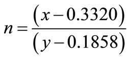 (2)
(2)
where (x, y) is the chromaticity coordinates. The chromaticity coordinates is based on standard tristimulus (X, Y, Z), defined by the International Commission on Illumination (CIE). The transformation from RGB to CIE color space (X, Y, Z) is
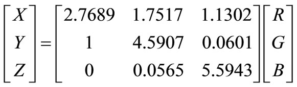 (3)
(3)
The transformation from (X, Y, Z) to chromaticity coordinates is 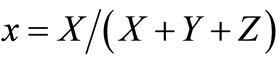 and
and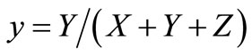 .
.
2.3. Color Rending Index (CRI)
The color rendering index (CRI) is a quantitative measure of the ability of a light source to reproduce the colors of various objects faithfully in comparison with an ideal or natural light source [4].
2.4. Multiwavelength LED Spectrum
A composite light spectrum is a linear combination of each LED spectrum, Si(l),
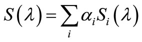 (4)
(4)
where ai is the proportion under equivalent power assumption. The goal is to make S(λ) close to those CIEdefined standard light spectrum of D50, D65, and D75, choosing color temperatures of 5000 K, 6500 K, and 7500 K, respectively. An objective function E can be defined in order to compute those optimums of ai,
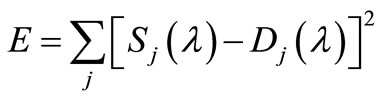 (5)
(5)
where color temperature 5000 K, 6500 K, and 7500 K are for j = 1, 2, and 3, respectively and Dj(l) is the spectrum of the CIE-defined standard light source.
2.5. LED Power Source with Power Factor Correction Functionality
The most attractive and beneficial attribute of LED lighting technology is its energy efficiency. LED power supply may come from a DC power source or, alternatively, transforming from AC power source after passing through a rectifier; basically, a DC power source may not provide any power factor correction (PFC) functionality as well as dimming capability for LED. Therefore, a flyback converter is included in the proposed LED power source module. The proposed LED drive with PFC is shown in Figure 1.
2.6. LED Dimming Design
Varying the forward drive current can dim an LED array; using a voltage regular or a variable resistor will accomplish the dimming requirement. An alternative way is to employ PWM. Two key factors, pulse width and duty cycle, can make LED light to vary its intensity. By turning the LED off for a short period of time will illude the human eyes, perceiving the LED as a continuous light stream. Therefore a LED drive circuitry is required to produce appropriate pulse width and frequency. The propose LED dimming design uses LM555 timer and variable resistor for the control of output pulse width. Figure 2 shows the design of dimming circuitry.
3. Simulation and Experiment
A flyback converter with power factor correction functionality in combination with LM555 timer generating PWM signal is made to implement on a LED array, consisting of three cascade LEDs. The output of the flyback converter is connected to the input of the LM555. These three cascade LEDs play the role of load. By varying the duty cycle and the ratio of the variable resistor, the PWM pulse width can be changed accordingly.
The input DC voltage range is 5 ~ 15 V; the load to the LED module is consisted of 4 cascade LEDs. LED dim-
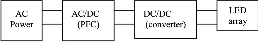
Figure 1. LED power source with PFC functionality.
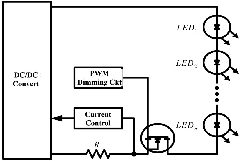
Figure 2. The schematics of cascade-connected switch dimming design.
ming drive is fulfilled via the tuning of variable resistor, width of PWM pulses, on/off timing of control/triggering of electronic switch. An example using resistor ratio (0.2, 0.5, 0.8) associated with duty cycle (0.2, 0.5, 0.8) and 5K Hz for the switching frequency of PFC is conducted to simulate the corresponding voltage output across LEDs and the forward current through LEDs. Simulation results show that the larger the duty cycle, the larger the output voltage; the forward current and output voltage are propositional to the variable resister ratio, as expected. Simulation also shows that a duty cycle of 0.8 or higher will always make the output quantities diverge.
Nine different kinds of LED chips, AlGaInP and InGaNA, are introduced in all constructed LED modules, being packaging with 4 parallel-arranged LED chips in order to increase their brightness level and emission area. A prototype of multi-wavelength LED light source with dimming capability is constructed, and is shown in Figure 3.
The wavelengths and nomenclatures are listed in Table 1. Three designated mix of color and their associated
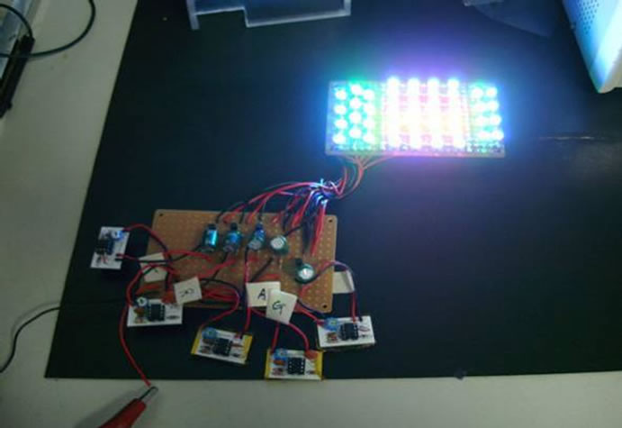
Figure 3. The emission of the multiwavelength of the LED light source module.
percentage of emission are listed in Table 2.
Table 3 records the mimic of the color temperature/ chromaticity coordinates of natural light sources. Therefore the proposed multi-wavelength LED light source can mimic a variety of natural light sources ranging from outdoor to indoor. The performance of the proposed LED light source is also evaluated using the NIST’s scenario. The values of Ra, the general color rendering index, as well as the corresponding computed color temperature for all 14 samples are listed in Table 4, illustrating the performance of the proposed LED light source via Ra. 
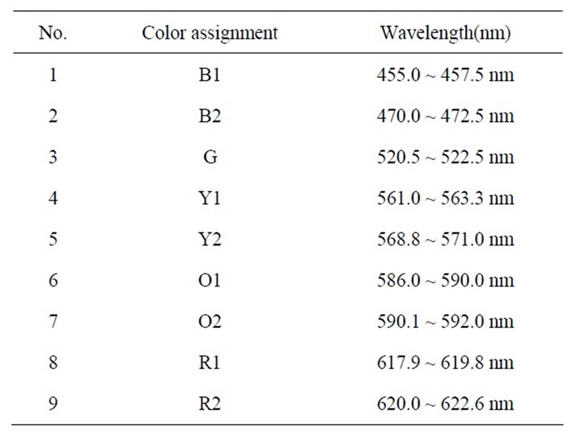
Table 1. Wavelenght of led chips.
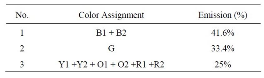
Table 2. Mix of led light.
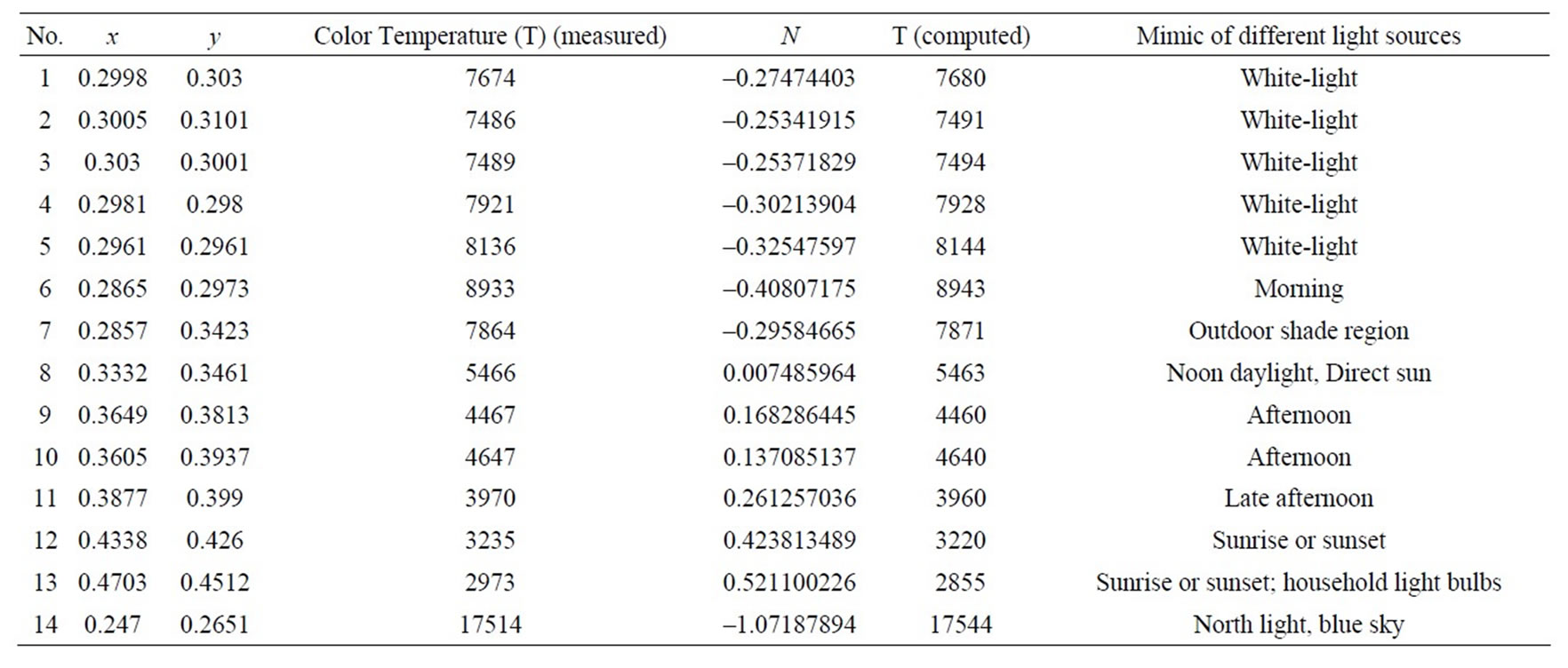
Table 3. Mix of led light.
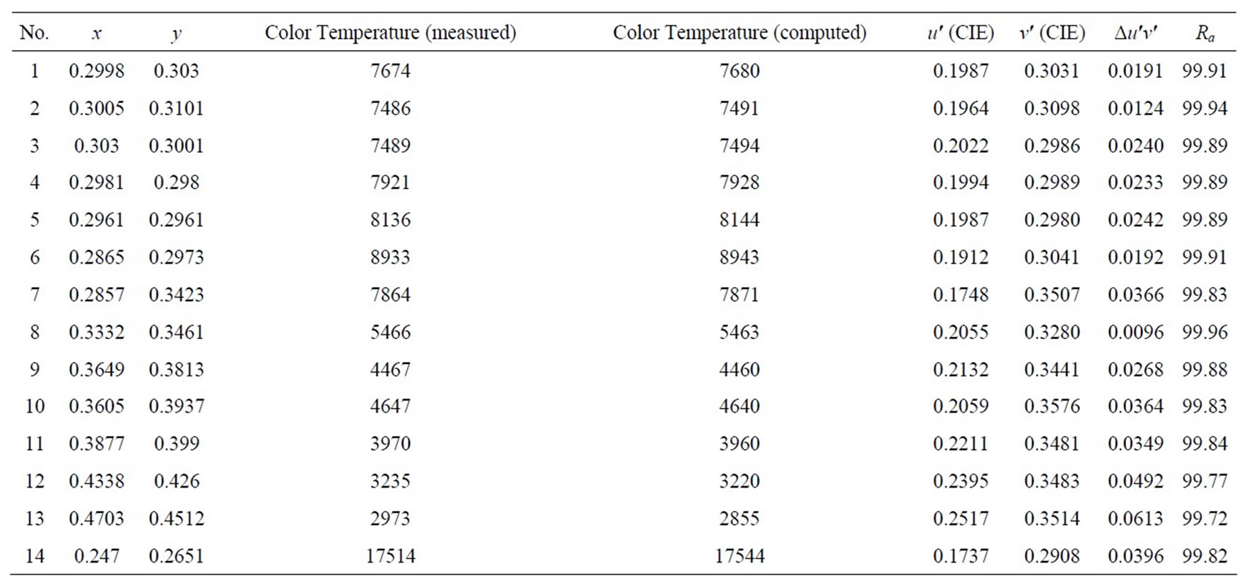
Table 4. Measurements (based on D65).
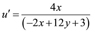
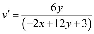
and  are defined by Equations (6) and (7).
 (6)
(6)
 (7)
(7)
transforming CIE’s chromaticity (x, y) into  and
and .
.  is the Euclidean distance between the CIE 1960 target chromaticity and the Planckian chromaticity coordinates [6,7].
4. Conclusion
An artificial multiwavelength/multichip LED light source with dimming control, consisting of 9 different LED chips, is implemented to achieve the goal of this paper, i.e., obtaining high CRI value. The key feature is to introduce PWM, power factor correction, and an electronic switch in the design of circuitry; dimming function is also included in the design. The verification of the proposed LED light source to mimic the natural light source is conducted through the comparisons of the measurements of color temperature with the computed ones. The manipulation of color rendering, a figure of merit for any white light source, is fulfilled as well, and the performance of the proposed LED light source is visualized via those high CRI values, which in average are greater or equal to 98%.
5. Acknowledgements
We would also like to thank National Formosa University for granting us the subsidies in 2010 Excellence in Teaching Project, giving us the opportunity to work this project.
REFERENCES
- E. F. Schubert and J. K. Kim, “Solid-State Light Sources Getting Smart,” Science, Vol. 38, 2005, pp. 1274-1278. doi:10.1126/science.1108712
- C. Biber, “LED Light Emissions as a Function of Thermal Conditions,” 24th IEEE SEMI-THERM Symposium, 2008, pp. 180-184. doi:10.1109/STHERM.2008.4509387
- http://www.handprint.com/HP/WCL/color12.html
- C. S. McCamy, “Correlated Color Temperature as an Explicit Function of Chromaticity Coordinates,” Color Research & Application, Vol. 17, No. 2, 1992, pp. 142- 144. doi:10.1002/col.5080170211
- http://en.wikipedia.org/wiki/Color_temperature.
- http://en.wikipedia.org/wiki/Color_rendering_index.
- Improvement to Industrial Color Difference Evaluation, CIE 141-2001, Technical Report, ISBN: 9783901906084.