Journal of Modern Physics
Vol. 2 No. 9 (2011) , Article ID: 7144 , 6 pages DOI:10.4236/jmp.2011.29123
On Line Measurement of Reactivity Worth of TRIGA Mark-II Research Reactor Control Rods
1Institute of Nuclear Science and Technology (INST), Atomic Energy Research Establishment (AERE), Ganakbari, Savar, Bangladesh
2Department of Physics, Jahangirnagar University, Savar, Bangladesh
E-mail: {shilas_door, azharphyd, Ahmedfarhana66, shahinrecd}@yahoo.com, mrashid@agni.com, Palash.eng07@gmail.com
Received April 24, 2011; revised June 3, 2011; accepted June 23, 2011
Keywords: Reactivity, Worth, Measurement, Control Rod, Kinetic, Rod Drop, Visual Basic
ABSTRACT
The reactivity worth measurement system for control rods of the TRIGA MARK-II research reactor of Bangladesh has been design and developed. The theory of the kinetic technique of measuring reactivity has been used by this measurement system. The system comprises of indigenous hardware and software for online acquisition of neutron flux signals from reactor console and then computes the reactivity worth accordingly. Here for the TRIGA MARK-II research reactor, the reactivity measurement system was implemented with a dedicated circuit assembly and a conventional personal computer. A high-level Visual Basic real-time programming has been developed for data acquisition, reactivity calculation, online display (numerically as well as graphically), saving data, etc. To measure reactivity worth of TRIGA reactor control rods the rod drop experimental technique has been adopted. The results of tests experiments, carried out with the rod drop method for measuring various reactivity worth of control rods have been presented in the paper. A comparison between this results with the results using period method and that of computation method, demonstrated that the response of this reactivity measurement system is fast enough to monitor and measure the safety-related reactivity and power excursions in the reactor.
1. Introduction
Determination of various reactivity in nuclear reactors is usually performed by compensating the given reactivity with the control rods to maintain the critical state. Calibration of control rod (determination of reactivity worth per unit movement of control rod) is thus essential when the control rods are used as reactivity standards to measure the reactivity changes caused by any other perturbation in a reactor. Hence, the control rod worth measurement is a key point in reactor physics. It provides the reactor operator with a direct indication of net reactivity, which is a much more definitive indication of the nuclear status of the core. It offers greater safety in reactor operation and aids the task of reactivity management; therefore it is strongly recommended as meter indication in the Control Room. Also periodic measurement of reactivity worth of control rods is one of the licensing requirements for any nuclear reactor. Many countries however, already developed their own reactivity measurement system [1-4].
A variety of experimental techniques have been developed to measure control rod worth. Such methods can be classified as either static or dynamic measurement techniques. Amongst them the positive period method and the rod-drop method are most popular dynamic methods [5] of control rod worth measurements. The period method is commonly utilized for positive reactivity measurement. This method initially yields differential rod worth data, i.e., it gives the worth of separate segments of the rod. These separate (differential) worths can then be combined to give an integral or total rod worth curve. Here, the reactor is made supercritical by withdrawing the control rod to be calibrated a certain amount, and the resulting (positive) period is determined from the measured doubling time to derive the reactivity.
TRIGA MARK-II Reactor operation group of Bangladesh has been determining the reactivity worth of parts of a control rod (i.e. the differential reactivity) since long by means of the period method. The total reactivity worth then can be determined by adding the reactivity worth of all parts of the control rod (i.e. by integrating the differential reactivity). But the total worth can not be determined directly by this method because the positive reactivity effect is too large for a safe procedure. Also this technique works well for positive reactivity insertion and hence positive periods, however for negative reactivity insertion; the negative periods are dominated by the longest delayed neutron precursor decay and hence provide very low sensitivity to a negative reactivity. Therefore, for direct on line reactivity worth measurement this procedure is not feasible.
On the other hand the rod drop method yields integral rod worth data directly. The control rod, that’s worth to be measured is dropped from a certain position at the critical state, and the resulting decay of the neutron flux is considered and then measured the reactivity worth accordingly. This method is utilized for measurement of negative reactivity, where the period method is no more applicable. The developed reactivity measurement system follows rod drop method. In this experiment the integral reactivity worth has been determined directly by dropping the control rod into the core while the reactor at critical and then analyzed the power transient caused by the negative reactivity insertion. The behavior of reactor power as a function of time can be found by solving the reactor kinetic equations.
Data acquisition system for monitoring and/or measuring various operational parameters of TRIGA research reactor of Bangladesh as well as its gradual improvements has been some important instrumentation works [6-8] around the research reactor of Bangladesh. Present work, on line reactivity measurement system, is one of the latest instrumentation works in this area. The objective of this experiment is to on line measurement of the reactivity worth of all control rods of the TRIGA Reactor directly by the rod drop method.
2. Reactivity Worth Measurement Device
An indigenous dedicated hardware with a real time software are the fundamentals of the developed worth measurement device. The hardware part is used to control the acquisition of power channel data from the reactor console and then interface this signal with a PC through the parallel port. The software part control the direct parallel port read/write operation, reactivity calculation, and online display and plotting of reactivity, saving data, etc.
An easy way to comply with the conference paper formatting requirements is to use this document as a template and simply type your text into it. (Figure 2)
2.1. Hardware Unit
The basic circuit diagram of the worth measurement system is given in Figure 1. The analogue input terminal (ANA-IN) of the device is directly connected to reactor console. As from the reactor operation safety point of view it is very important to protect any possibility of loading of the neutron flux source channel of the reactor console, a FET input operational amplifier IC CA3140 is used here as an unity gain input buffer to isolates the reactor console from rest of the circuitry. The signal acquired from reactor is represented by an analogue voltage; therefore an ADC is required to get a digital output for further steps. For this purpose ADC IC AD574 has been used here. The AD574 chip is a complete 12 bit [9] successive approximation analogue to digital converter with 3-state output buffer circuitry for direct interface to an 8, 12, or 16 bit microprocessor bus. The IC takes a conversion time of 25 mS. The ADC unit gives standard TTL level digital outputs that are read by the software through the computer interface unit. To access this digitized acquired data through computer, parallel port interface was used here. The bi-directional parallel port allows eight input/output data lines (D0 - D7), four output control lines (C0 - C3) and five input status lines (S3 - S7) through Data Register, Control Register and Status Register, respectively, that can be accessed directly by an external device [10]. Thus it required minimum external circuitry to interface this port with an external hardware. Some of the control bits (C0, C1 and C3), at the output of the parallel port, gives the inverted output from the
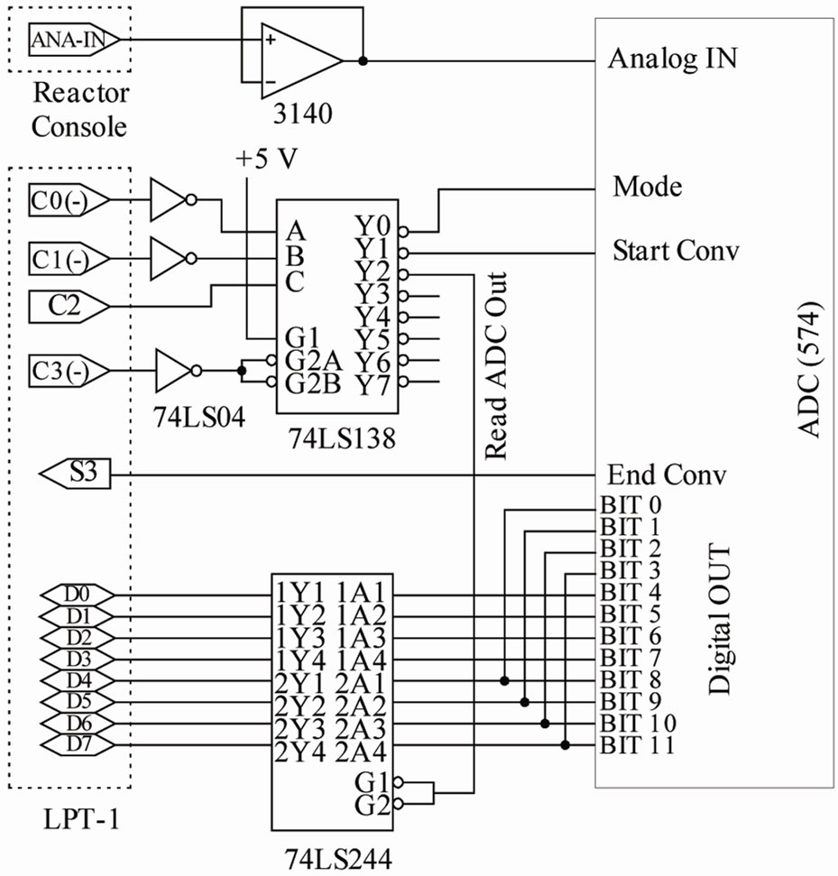
Figure 1. Circuit diagram of the hardware part of the control rod worth measurement system.
setting of the control register bits. The inverted control bits are inverted again by the 74LS04 IC to provide the same control bits, as setting of the control register, for decoding purposes. The IC 74LS138 was used for decoding the control bits to provide various control pulses for the ADC such as, ADC mode select, start conversion and ADC output read, as required for the system. The TTL buffer IC 74LS244 was used for reading the digital data from the output of the 574 IC.
2.2. Software Unit
The programming language adopted in the project was Visual Basic. The developed software offers the user to handle the program either in Off Line or On Line mode. For off line mode, any file of previously saved digital
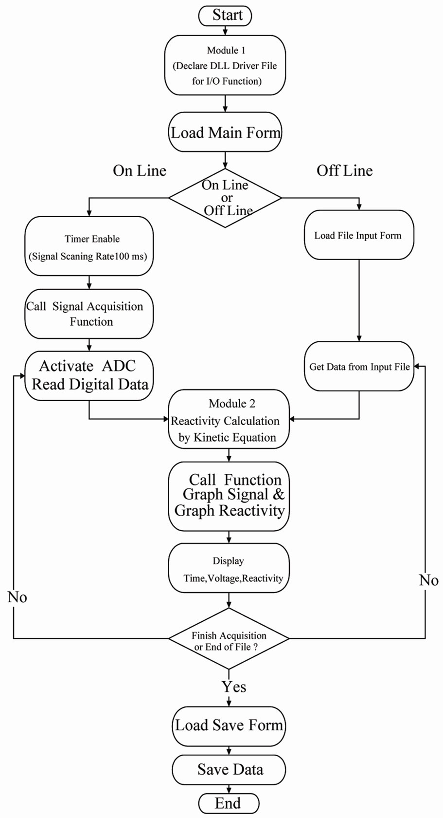
Figure 2. Flowchart of the program execution of worth measurement.
data of signal and time can be selected as input file for calculating the reactivity. In on line mode, signal is acquired instantly during reactor operation (any power level change) and reactivity calculation is performed accordingly like any real time program. “Timer” function of the Visual Basic language [11] has been used to set up the speed of signal scanning.
Here time interval between two successive scanning has been selected at 100 ms. As VB does not have standard I/O read/write functions to access the mentioned registers, the I/O read/write functions have to be called in VB environment, importing them from a dynamic link library (DLL) file. The DLL file can be easily developed by C++ or by any suitable programming languages to serve as an interface between VB and the external hardware. For present work The DLL file, “inpout32.dll” was downloaded from the internet. Mathematical calculations have been done with the digital voltage and its corresponding time of acquisition using kinetic equations to get reactivity value. Then along with the digital display of reactivity, signal and time values, graphs for reactivity versus time and signal versus time have been plotted. Hence the program can display the graph and numerical data simultaneously at each power signal level.
3. Equations for Reactivity Calculation
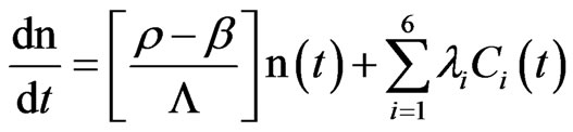
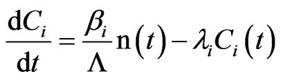
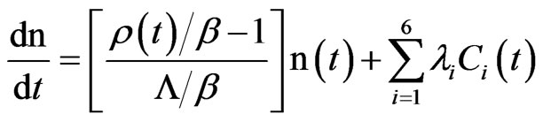
The point kinetic equations can be satisfactorily expressed the time behavior of the neutrons population in a reactor core induced by changes in reactor multiplication factor k(t). The worth measurement system describes in the paper provides the finite solution of the point kinetic. The point kinetic equations used here to calculate reactivity worth of control rod are:
 (1)
(1)
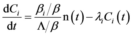
 (2)
(2)
We can rewrite the equations as follow:
 (3)
(3)
 (4)
(4)
Usually reactivity is dimension less; however, it can be expressed in dollar [12] when the reactivity (ρ) is divided by  (delayed neutron fraction). General Atomic (GA), the supplier, as well as the Operation & Maintenance Unit of TRIGA Mark-II Research Reactor, Bangladesh, has been using the dollar as a standard unit to measure the reactivity.
Therefore, putting  = ρ* (Reactivity in dollar) and
  = L* and rearranging above equations, the kinetic equations can be expressed as:
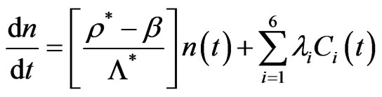 (5)
(5)
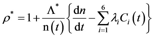 (6)
(6)
Clearly, at t = 0 (before any reactivity insertion, ρ = 0):
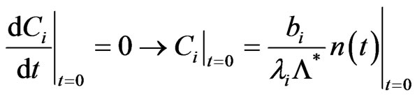 (7)
(7)
Also:
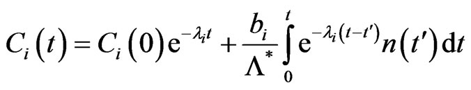 (8)
(8)
If time variable “t” is discretely divided (t = kh, k = 1, 2…), and furthermore, n is a set: (n0, n1, n2,…, nk…), we can rewrite:
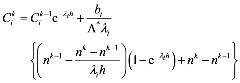 (9)
(9)
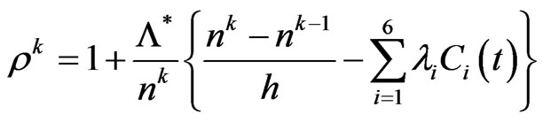 (10)
(10)
Here n = neutron flux (proportional to the reactor power)/ Neutron population t = time (sec)
ρ = time dependent reactivity = [k(t) – 1]/k(t)
Ci = concentration of the i:th fraction of the delayed neutrons’ precursors
λi = decay constant of precursor for group i (sec–1)
b = sum of the delayed neutron fractions bi = delayed neutron fraction for group i h = time deference between two successive sampling Solving the equations for precursor concentrations of 6 groups and putting their summation in the equation for reactivity, the algorithms for control rod reactivity worth measurement system were derived.
4. Rod Drop Experiment
The control rod worth measurement system has already been interfaced with the TRIGA reactor console for the on line control rod worth measurement by rod drop technique. The step by step procedures used here for control rod worth measurement following rod drop method are:
1) The measurement system has been connected to the reactor log power channel.
2) The real time base program has been set up to run mode.
3) The reactor critical state has been brought at very low power level, for example 50 W with the test rod withdrawn fully and maintaining the criticality by other 5 rods.
4) Then the test control rod has been rapidly dropped into the reactor core that cause sudden power level change 5) Finally the power level change has been Measured and reactivity worth has been calculated by point kinetic equations 6) The whole sequence of steps from 1 to 5 has been repeated for other five control rods.
5. Results and Discussion
To check the performance of the developed control rod worth measurement system, several rod drop experiments have been made on test basis keeping reactor on 50 W. In this case reactor power was decreased abruptly and corresponding data of neutron population was acquired through the hardware unit. Then the real time program performed the worth calculations using kinetic equations and displayed the result both in numerically and graphically. Validation has been performed by comparing the measured values with the results obtained from the measurements using period technique as well as with the theoretical method. Table 1 shows the two sets of average reactivity worth of 6 control rods measured by the developed measurement system implementing rod drop method by Reactor Engineering and Control Division (RECD) and by Reactor Operation and Maintenance Unit (ROMU) using period method. A comparison between two measured values reveals that the two sets of data agrees quite well within the margins of the experimental error. Also Table 2 presents the calculated data
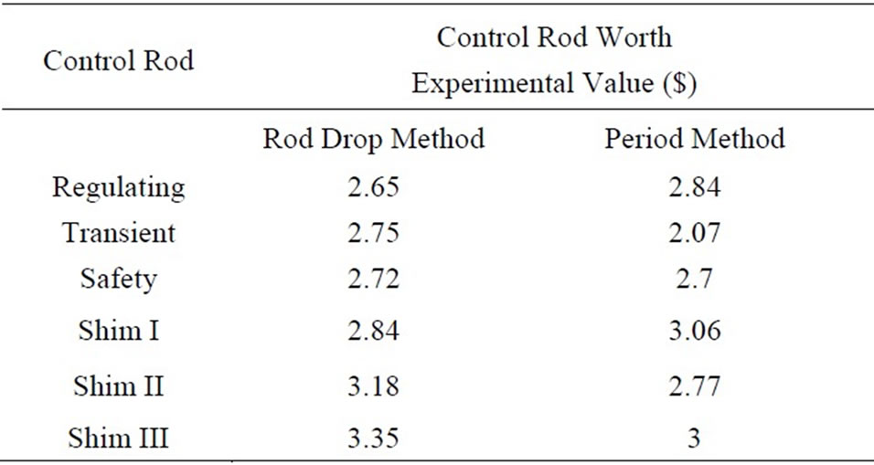
Table 1. Experimental control rods worth by rod drop and period method.
of 6 control rods reactivity worth by MVP model for 550 MWD burnup cores of TRIGA reactor and corresponding C/E values are summarized in Table 3. The statistical uncertainty of 1 standard deviation is shown in Table 3 which indicates very reasonable agreement with calculated and experimental results.
In this pertinent, it can be mention that from practical experience of international research reactor analysts (MEXT/NSRA mission, 3 March 2007), calculation results always vary with the measured values in the case of burnt core. Figure 3 is the practical Time (s)-Reactivity ($) plot that shows the reactivity change of the reactor from the critical condition (zero reactivity) for the fulllength change of the 6 control rods. It manifests from the plot also that the results obtained from developed system using rod drop method has reasonable agreement with the results obtained from period method or Monte Carlo results. For instance, the average reactivity worth of the Safety rod measured by RECD and by ROMU is found $2.72, $2.7 respectively which is very close to that value calculated by MVP ($2.74). Therefore, it has been observed that the digital reactivity meter is working properly.
6. Conclusions
The control rod worth measurement System has been designed and developed for the TRIGA Mark-II research
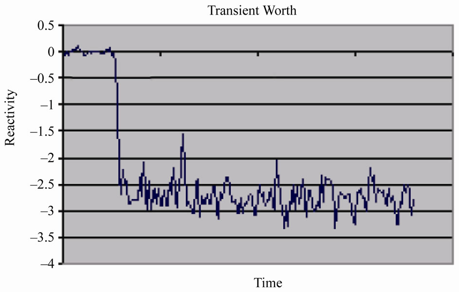
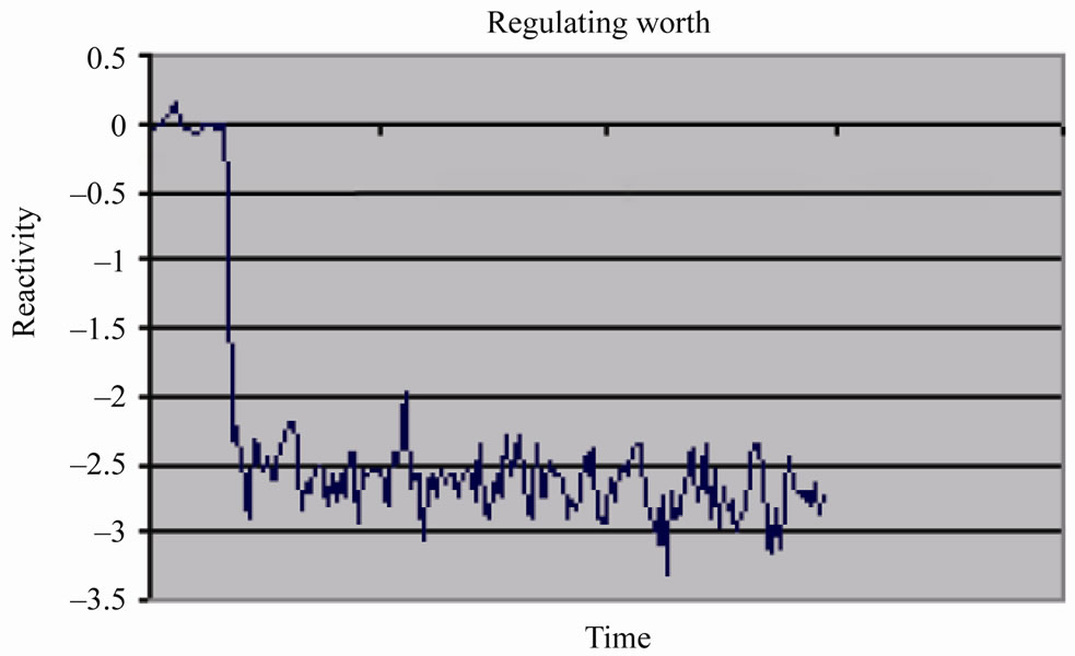
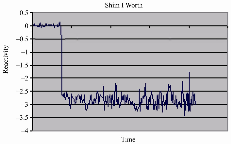
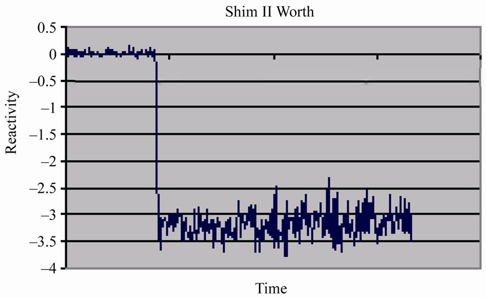
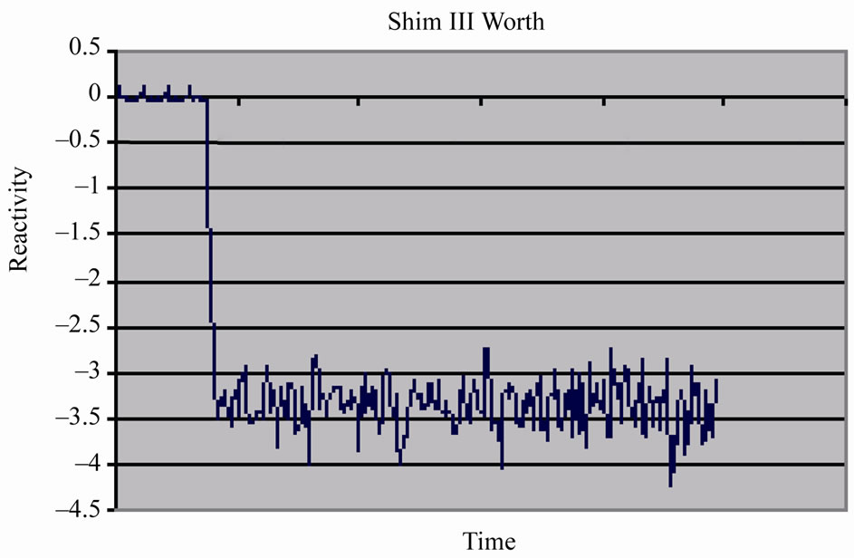
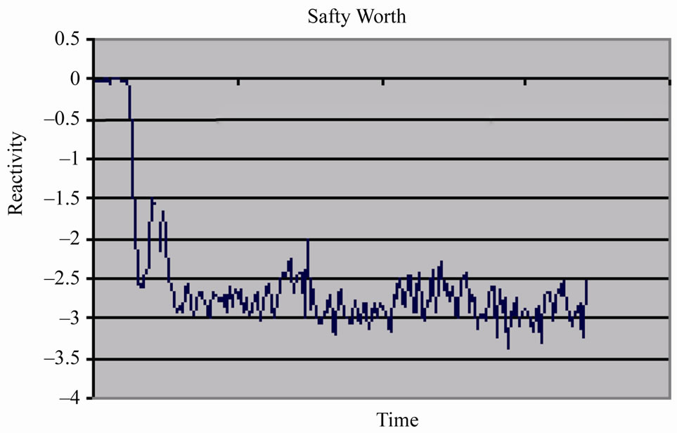
Figure 3. Reactivity worth of six control rods.
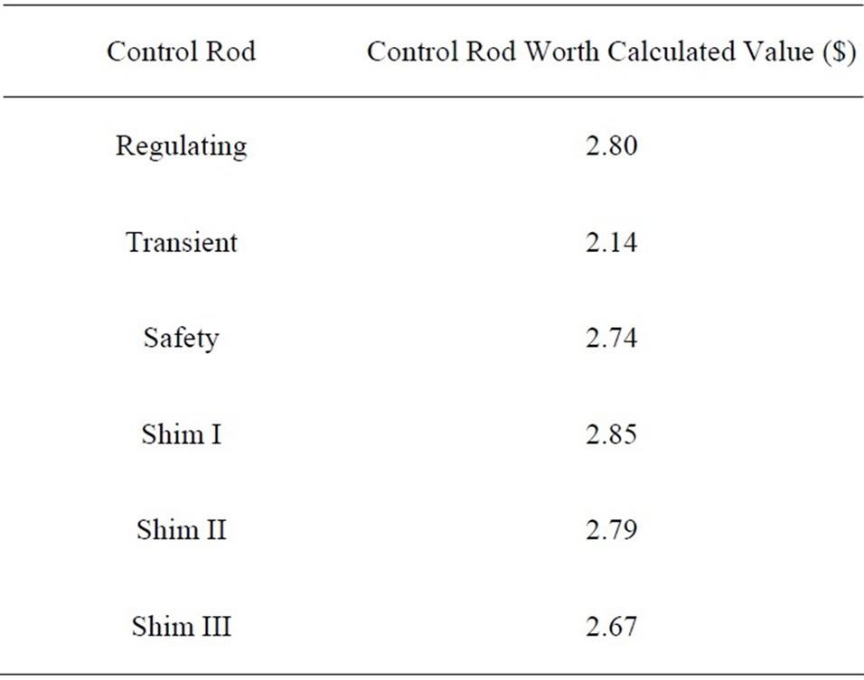
Table 2. Calculated control rods worth.
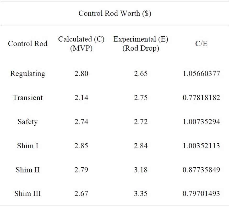
Table 3. Calculated and experimental control rod worth.
reactor of Bangladesh. The rod drop dynamic technique has been applied here to carry out the experiment. A simplified method based on the point reactor kinetic equations has been implemented for the computation of the reactivity. The reactivity worth measurement system has been tested successfully in the TRIGA Mark-II research reactor, Bangladesh. Validation has been performed by comparing the experimental data from developed system with the experimental data using period method and the calculated data from theoretical method based on the computer code like Monte Carlo code MVP. The result of validation agrees quite well within the margins of the experiment. Expectantly the developed system will be used for continuous on line measurement of control rod worth of TRIGA reactor, Bangladesh
REFERENCES
- S. A. Ansari, “Development of on-Line Reactivity Meter for Nuclear Reactors,” Nuclear Science, IEEE Transactions, Vol. 38, No. 4, 1991, pp. 946-952.
- S. E. Binneyand A. J. M. Bakir, “Design and Development of a Personal—Computer-Based Reactivity Meter for a Research Reactor,” Nuclear Technology, Vol. 85 APR, Oregon State University, Corvallis, 1989, pp. 97331-105902.
- R. J. Engle, “Experience with an on-Line Reactivity Balance Calculation as a Guide for Reactor Operation,” Proccedings of Conference on Incipient Failure Diagnosis for Assuring Safety and Availability of Nuclear Power Plants, CONF- 671011, Gatlinburg, 30 October-1 November 1967, p. 58.
- N. Jahan, M. M. Rashid, M. A. Khayer, H. Blaumann, J. Longhino and F. Sánchez, “Design and Development of a Real Time Digital Reactivity Meter for a Research Reactor,” Journal of the Bangladesh Electronics Society, Vol. 5, No. 2, 2005.
- J. J. Duderstadt and L. J. Hamilton, “Nuclear Reactor Analysis,” John Wiley & Sons, New York, 2005, p. 268.
- A. A. O. M. Ahad, “Data Acquisition System for the 3 MW TRIGA Reactor at AERE Savar,” IAEA-TECDOC- 1004, 1998, p. 11.
- M. M. Rashid, N. Jahan, M. A. Khayer and R. Mondal, “Data Acquisition from a Multichannel ADC Using Bidirectional Parallel Port as an Interface,” Journal of the Bangladesh Electronics Society, Vol. 4, No. 2, 2004.
- M. M. Rashid, N. Jahan, M. A. Khayer and R. Mondal, “Transition from ISA Bus Interface to Parallel Port Interface for Computer Based Control & Instrumentation,” Journal of the Bangladesh Electronics Society, Vol. 4, No. 2, 2004.
- M. M. Rashid, N. Jahan, M. A. Khayer and R. Mondal, “Transition from ISA Bus Interface to Parallel Port Interface for Computer Based Control & Instrumentation,” Journal of the Bangladesh Electronics Society, Vol. 4, No. 2, 2004.
- W. L. Rosch, “Hardware Bible,” Premier Edition, New Delhi, 1997.
- E. Petroutsos, “Mastering Visual Basic 6,” BPB Publications, New Delhi, 1998.
- S. Glasstone and A. Sesonske, “Nuclear Reactor Engineering,” CBS Publishers & Distributors, Delhi, 1986, p. 250.