Smart Grid and Renewable Energy
Vol.2 No.3(2011), Article ID:6564,5 pages DOI:10.4236/sgre.2011.23034
Sizing of Converters Interfacing the Rotor of Wind Driven DFIG to the Power Grid
![]()
Power Electronics and Energy Conversion Department, Electronics Research Institute, Cairo, Egypt.
Email: salehmahmoud36@yahoo.com, eskander@eri.sci.eg
Received April 19, 2011; revised May 19, 2011; accepted May 26, 2011.
Keywords: Double Fed Induction Generator, Converter Sizing, Cost lowering, Wind Energy Conversion System
ABSTRACT
In this paper, the operation of the Double Fed Induction Generator (DFIG) in the range from synchronous speed down to sub-synchronous speeds is analyzed using the power-flow approach. The objective of this analysis is to determine a ceiling for the rating of the converter interfacing the rotor of the wind driven double fed induction generator (DFIG) to the grid. Sizing the converter is an important issue in determining the economic viability of using the DFIM as a generator at synchronous and sub-synchronous speeds in wind energy conversion systems. The size of the converter is proved to be less than 10% of the rated power of the DFIG, which is 40% to 67% lower than that estimated in previous publications.
1. Introduction
The world community is very much concerned about “climate change” and specifically the global warming, which is mainly attributed to the increase of greenhouse gases (GHG) in the atmosphere. The GHG are mainly produced due to burning fossil fuels (oil derivatives, natural gas, and coal) and other organic matters (biomass) for power generation or other industrial purposes. The utilization of renewable energy resources (hydro, wind and solar) as alternatives to fossil fuels can mitigate the problem of GHG increase in the atmosphere.
Most of the hydro-energy resources all over the world, (except in some parts of the African continent), are being utilized for electric power generation. The second in row of renewable energy resources is the wind, which is considered the most promising and fastest growing energy resource worldwide.
The Global Wind Energy Council in Brussel, announced on February 2010, that the world’s wind power installed capacity grew by 31% in 2009, adding 37.5 GW to bring the total installed capacity of wind energy conversion systems up to 158 GW. The continued rapid growth in wind power capacity, despite the worldwide financial crisis and economic downturn, is testament to the inherent attractions of wind systems due to their environmental, economic, and technical merits. However, wind energy utilization has, beside the many merits, two main drawbacks, namely; the intermittent unpredictable nature of the wind resource, and the relatively large investment cost of the components of the wind energy conversion system (WECS).Of course, the nature of the wind could not be changed, but WECS could be connected to large power grids, and operate as fuel savers during the availability of reasonable wind speeds, while the fossil fuel fired power plants connected to the grid act as backup during the low wind speeds. At this point, the advantages of adjustable speed wind generators (ASG) should be mentioned, since this type of WECS can generate at all power levels and can extract the maximum amount of energy from the available wind speeds. The ASG are more cost effective than the fixed speed generators. They, also, have less mechanical stresses, improved power quality, and increased stability margin of the electric power grid.
The ASG can further be subdivided into two types, either those based on synchronous generators, or those based on doubly fed induction generators (DFIG). The DFIG based WECS dominate because of the significant reduction of the power rating and cost of the converter, the possible speed regulation for optimal utilization of energy, the possibility of controlling the reactive power, and finally the possibility of sub-synchronous , synchronous, and super-synchronous operation of the induction generator. Most, if not all the sold WECS during the last years, are DFIG-based systems. The market share of DFIG systems (75%) surpassed many times the other types of WECS.
In this paper, the size and consequently the cost of one of the main electrical components of the DFIG-based WECS, namely, the converter, is investigated. It is proved that the size of the converter (10% of rated DFIG power) is much less than estimated in previously published [1] papers (25% - 30%). The behavior of the DFIG at synchronous speed is also investigated.
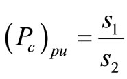
2. The Power Handled by the Converter in the Sub-Synchronous Range
The behavior of the electric power generating systems is usually governed by the demand side (electric load, grid requirements, etc.). The prime movers (fossil fuel fired turbines, hydro-turbines, diesel engines, etc.) are always responding to the needs of the power grid or loads. In the case of WECS, their behavior is governed mainly by the supply side, namely, the wind resource (wind speed and wind power). Thus it is more logical that any analysis of the performance of WECS starts from the prime mover side, i.e. wind turbine.
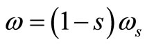
All manufactured variable speed wind turbines are pitch controlled type. Between the cut-in wind speed and the rated wind speed, the angular speed of the wind turbine and consequently the DFIG rotor speed changes to maintain an optimal tip speed ratio for maximum energy yield. Generally speaking, wind turbines are run along the so called maximum power point tracking [2] curve. Figure 1 shows the most practically adopted shape for variation of the output mechanical power of the wind turbine versus the generator angular speed w. It shows a quadratic shape from the cut-in speed wc, to the rated speed wr, which correspond to the cut-in and rated wind speeds respectively.
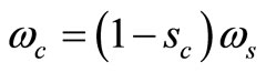
The DFIG has its own synchronous speed ws corresponding to its number of poles and power frequency of the grid to which it is connected. The value of wr is usually 5% to 10% higher than ws.
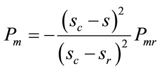
It is well known [3] that the power flowing in the rotor of the DFIG has three components; namely, the mechanical power input to the rotor from the wind turbine Pm, the electromagnetic power transferred from rotor to stator Pg, and the slip power Ps which is the electrical power transferred between the rotor and any external electrical source or load (e.g. converter) via the wound rotor slip rings. Ps is partially consumed in rotor windings as copper losses and may be written as:
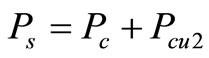 , where Pc is power handled by converter and Pcu2 is rotor copper losses.
These components are inter-related as follows under any conditions:

Figure 1. Typical power-wind speed characteristics.
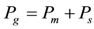
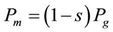
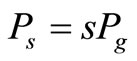
where s is the rotor slip.
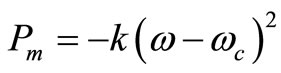
Neglecting the mechanical losses in the coupling, gearbox, and the rotor, then the mechanical power input to the rotor will be equal to the output power of the wind turbine. Pm = –Pt
The negative sign indicates that Pt is the turbine output while Pm is DFIG input In the speed range from wc to wr the mechanical power input to the DFIG at any angular speed can be expressed as:
 k is a constant (1)
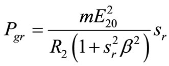
At the rotor angular speed wr corresponding to rated wind speed, the input mechanical power Pmr is given as:
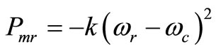 (2)
(2)
From Equations (1) and (2) and considering:
the input mechanical power to the rotor of DFIG can be expressed as:
 (3)
(3)
where sr and sc are the rotor slips corresponding to the rated and cut-in rotor angular speed respectively.
Since the amount of mechanical power converted to electrical power by the DFIG could not exceed the output power of the wind turbine, therefore, the slip power Ps (which is approximately equal to the power handled by the converter), could not exceed , at any slip, the value given by the following Equation:
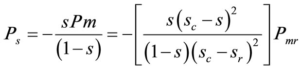 (4)
(4)
Figure 2 shows the variation of the per unit values of Pm, Pg, and Ps as functions of the slip s in the range from cut-in to the synchronous rotor speed for an assumed practical value of sc = 0.5 Also, the variation of the per unit value of Ps versus the slip s is shown in Figure 3, in enlarged scale. It is clear from Figure 3 that there exists a slip smax at which the magnitude of the slip power has a maximum value. This value of slip is determined by equating the derivative of Ps to zero, i.e. dPs/ds =0.
Differentiating Equation (4) and, equating the derivative to zero, and manipulating gives the following equation:
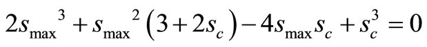 (5)
(5)
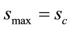
The three roots of Equation (5) are:
 and
and 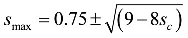
The only valid root which lies between the cut-in and rated speeds is:
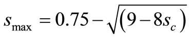 (6)
(6)
In practice the rated angular speed of the wind turbine ranges from 1.5 - 2.5 the cut in speed (wr = 1.5 to 2.5 wc).
Knowing that the rated speed is 5% to 10% higher than the synchronous speed of the DFIG, then the practical range of sc is between 0.35 and 0.6. Therefore, the slip power Ps, (or approximately the power handled by the converter Pc = Ps ± Pcu2) could not exceed the value given in Equation (7):
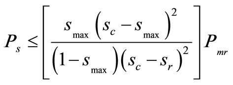 (7)
(7)
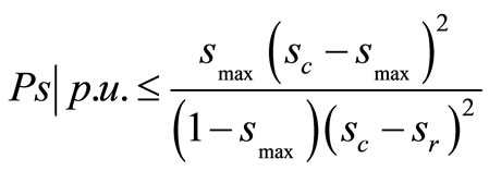 (8)
(8)
The per unit maximum power handled by the converter is shown in Figure 4 as function of the cut-in slip sc within the practical range of sc = 0.35 to 0.6. Figure 4 shows that the power handled by the converter ranges between 3.6% and 9.68% of the DFIG rated mechanical power, which is slightly less than the rated air gap power and consequently the rated output of the DFIG. The lower the value of sc (the larger the value of the cut-in angular speed), the smaller will be the size of the converter. The value of sc = 0.5 is a very common practice, i.e. the rated speed is approximately double the cut-in speed, and the corresponding converter size will not exceed 7.5% of the DFIG rated power. Since the cost of converter depends mainly on its rating in approximately linear relation, then when properly selecting the converter its cost will be reduced by 40% to 67% of that estimated in previous publications [1]. For the 1.5 MW to 3 MW size
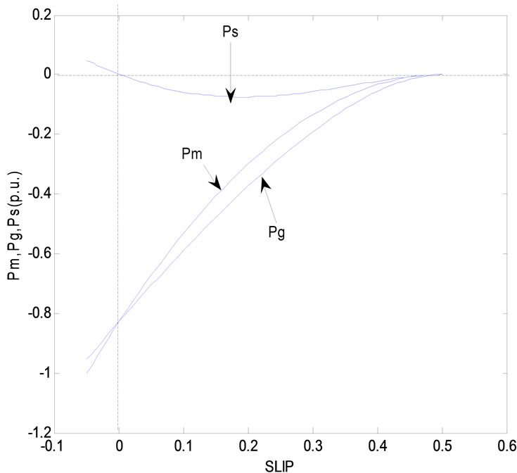
Figure 2. Variation of Pm, Pg, and Ps with slip.
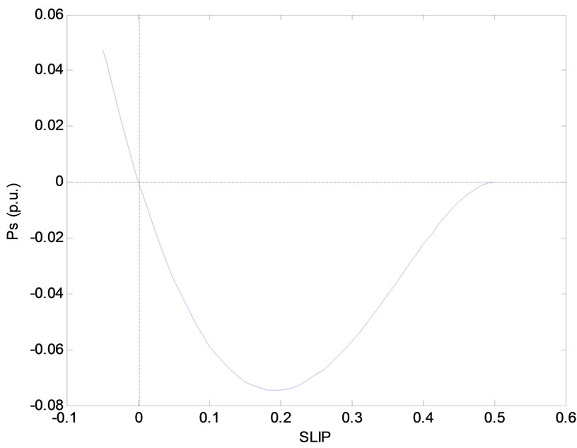
Figure 3. Variation of the per unit value of Ps versus the slip s.
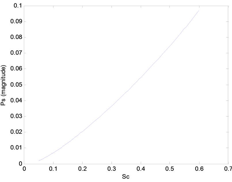
Figure 4. Maximum power handled by the converter.
WECS, the cost of the power converter range between 6.4% and 12.5% of the total WECS components cost. Therefore the proper selection of the DFIG power converter size will reduce the total system cost from 2.5% to 8%.
3. The Power Handled by the Converter at Synchronous speed
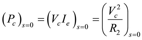
The analysis in Section 2 of this paper, applies to the operation of DFIG from the cut-in speed up to just before the synchronous speed i.e. sc £ s < 0. This section is devoted to the operation of the DFIG at synchronous speed i.e. s = 0, where the DFIG will operate as a synchronous generator.
The rated power of the DFIG is calculated during the design phase as being the machine output when the rotor is short circuited. It could be easily proved that [3]:
 (9)
(9)
where Pgr = rated air gap power = rated output power (neglecting the stator losses)
m = number of phases of the DFIG
 rotor induced voltage at stand still
 rotor resistance
 = ratio of stand-still rotor leakage reactance to the rotor resistance
 (10)
(10)
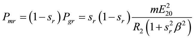
From Equations (2) and (10), the input mechanical power at any slip s can be expressed as:
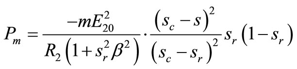 (11)
(11)
At synchronous speed i.e. s = 0
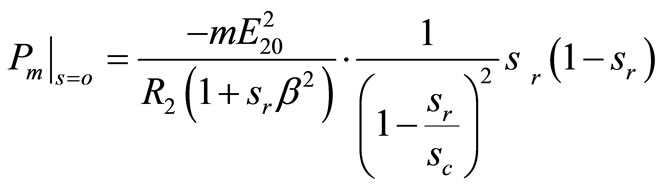 (12)
(12)
From the DFIG rotor side, following the rotor power flow approach as given in ref. [3], maximum air gap power transferred from the rotor to the stator of the DFIG at any slip s is expressed as
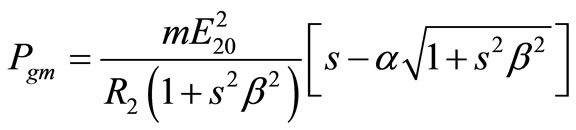 (13)
(13)
where a is the ratio of the converter output voltage to the stand-still rotor induced voltage.
Pgm is a continuous function of the slip from the sub-synchronous to the super-synchronous range, therefore at synchronous speed the value of Pg at s = 0 can be expressed as
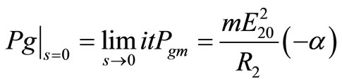 (14)
(14)
The mechanical power input to the rotor, if the mechanical losses are neglected, will be converted to electrical power transferred to the stator through the air gap. Equating Pm and Pg at s = 0 from Equations (12) and (14), the following expression for a can be obtained
 (15)
(15)
Therefore the value of the d.c. voltage output of the converter Vc, that keeps the DFIG converting all its mechanical input power into electrical power is given as :
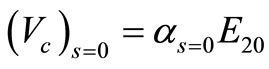 (16)
(16)
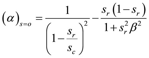
The variation of a at s = 0 with the cut-in speed at a value of rated slip sr = –0.05 is shown in Figure 5 for different values of b. It is clear from Figure 5 that the d.c. voltage output of the converter increases with the increase of the cutin slip. Thus the higher the value of b, the lower will be the value of a. Practically, the value of b for large DFIG is in the range from 8 to 10, and the cut-in slip is around the value of 0.5. Therefore, the d.c. voltage applied to the rotor circuit of the DFIG at synchronous speed will range between 3.4% - 3.6% of the rotor induced voltage of stand-still.
The power handled by the converter and at the same time consumed in the rotor circuit, is a very important parameter when assessing the performance of the DFIG operating as a synchronous machine
 (17)
(17)
From Equations (10), (15) and (16), the per unit value of the power handled by the converter (or consumed in the rotor circuit) can be expressed as:
 (18)
(18)
where,
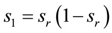
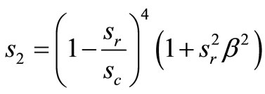
Figure 6 shows the variation of the converter per-unit power with the cut-in speed for different values of  . This power ranges between 2.8% and 3% of the rated value within the practical ranges of
  (8 – 10) and sc = 0.5. This power is equivalent to the power of the exciter of a synchronous machine.
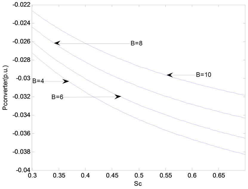
Figure 5. The variation of  with the cut-in speed.
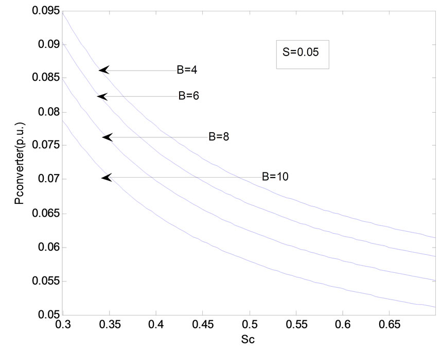
Figure 6. The variation of converter power with cut-in speed.
4. Conclusions
Operating the DFIM as a generator at synchronous speed is discussed. The magnitude of the rotor applied voltage essential for converting the mechanical output of the wind turbine into electrical power at synchronous speed is derived. Also, equations for the power handled by the converter at synchronous and sub-synchronous speeds are derived. These equations proved that the size of the converter is less than 10% of rated DFIG power, which is 40% to 67% lower than the estimated size in previous publications. This conclusion is in favor of deployment of DFIG as generator at synchronous and sub-synchronous speeds due to its lower cost when compared to conventional synchronous generators that need full power stator converters for power conditioning. Another advantage is its better efficiency, since more energy can be captured from the available wind.
Since the cost of converter depends mainly on its rating in approximately linear relation, then when properly selecting the converter its cost will be reduced by 40% to 67%. For the 1.5 MW to 3 MW size WECS, the cost of the power converter range between 6.4% and 12.5% of the total WECS components cost. Therefore the proper selection of the DFIG power converter size will reduce the total system cost from 2.5% to 8%. This cost reduction ensures the economic viability of WECS based on doubly fed induction generators (DFIG).
The results obtained in this paper could be very helpful for the designer of WECS by selecting the proper size of the converter.
REFERENCES
- J. Hu and Y. He, “Reinforced Control and Operation of DFIG-Based Wind Power Generation System under Unbalanced Grid Voltage Conditions,” IEEE Transactions on Energy Conversion, Vol. 24, No. 4, December 2009, pp. 905-915. doi:10.1109/TEC.2008.2001434
- D. Saidani, O. Hasnaoui and R. Dhifaoui, “Control of Double Fed Induction Generator for Wind Conversion System,” International Journal of sciences and Techniques of Automatic Control & Computer Engineering, Vol. 2, No. 2, December 2008, pp. 710-721.
- M. A. Saleh and M. N. Eskander, “Sub-Synchronous Range of Operation for a Wind Driven Double-Fed Induction Generator,” Journal of Power Electronics, Vol. 10, No. 1, January 2010.
List of Symbols
Ps slip power
Pc converter power
Pm mechanical power
Pg air gap power
Pcu2 rotor copper losses
Vc converter output voltage
Ic converter (rotor) current
E20 induced voltage rotor at stand still
R2 rotor resistance
s slip
smax slip at which slip power is maximum
w rotor angular speed
α ratio of converter to standstill rotor induced voltage
β ratio of standstill rotor leakage reactance to rotor resistance
Subscripts
c cut in values
r rated values
p.u. per unit values