Journal of Power and Energy Engineering
Vol.05 No.09(2017), Article ID:79492,21 pages
10.4236/jpee.2017.59014
Numerical and Experimental Study of a Multi-Generation Desalination Power Plant
Jacob R. Pleis, Dongmei Zhou
Department of Mechanical Engineering, California State University, Sacramento, CA, USA
![]()
Copyright © 2017 by authors and Scientific Research Publishing Inc.
This work is licensed under the Creative Commons Attribution International License (CC BY 4.0).
http://creativecommons.org/licenses/by/4.0/


Received: August 4, 2017; Accepted: September 27, 2017; Published: September 30, 2017
ABSTRACT
The demand for more efficient power generation is not only a prominent subject for environmental reasons but for economic reasons as well. Continuing growth in population contributes to more and more consumption of fresh water, demanding less expensive desalination production, especially in the regions with little or no natural fresh water. Multigeneration desalination power plants may provide solutions to these issues through advanced and efficient designs that are capable of supplying fresh water and power to remote or arid regions of the world. This paper examines the flexibility and versatility of multigeneration systems to showcase the myriad of combinations that are available to accommodate any specific application. It also proposes a specific design for a multi-stage flash desalination system that is powered directly by the exhaust gases of a natural gas micro-turbine capable of producing around 1 MW of electrical power. The performance characteristics, the fresh water produced per kW and the overall plant efficiency, are numerically investigated and compared with previous designs that were analyzed on a larger scale. It is determined that the multigeneration system can produce 56,891 gallons of fresh water per day and an estimated 4.07 tons of salt per day and that a small scale multi-generation desalting systems is feasible.
Keywords:
Multigeneration, Trigeneration, Cogeneration, Multi-Stage-Flash Desalination, Power Plant, Waste Heat Recovery, Numerical Analysis

1. Introduction
The increasing demand for energy today is alarming, especially considering that fossil fuels are essentially a limited resource and that greenhouse gases in mass quantities negatively affect our environment. The United Nations has projected that the world population will reach 8.5 billion people by 2030 [1] . And according to the US Energy Information Administration (EIA), the global energy consumption could be around 780 quadrillion Btu by 2035 compared to the 410 quadrillion Btu consumed by the world in the year 2000.
The trends are clear; the energy demand will only increase, and to avoid negatively affecting our environment we need to produce more efficient, cleaner energy. Renewable energies have seen tremendous attention and significant advancements over the past decade. Numerous wind turbines and solar panels have been installed in the United States as shown in Figure 1 and throughout the world, and consequently leaving multigeneration systems being highly neglected [2] . A solar panel may achieve 35 percent efficiency only during the daytime when converting energy from the sun and a typical coal powered, centralized power plant can only produce electricity at an efficiency of around 35 percent, but compare these to the 80 percent efficiency that a cogeneration system may achieve continuously.
Along with the demand for more energy, the demand for fresh water has never been greater. Population growth outpaces the ability to efficiently and safely supply fresh water to entire regions of the world. The common use of poor quality water, or unsanitary water, in developing countries causes 80% - 90% of all the diseases and 30% of all deaths [3] . One solution to meet this demand of fresh water is multi-stage flash desalination. This process consists of heating up saltwater, then lowering the pressure of the chamber or stage to make “flash” steam, which is then condensed and collected as fresh water. It was estimated that in 2007 the total capacity of installed seawater desalination plants worldwide was about 30 million cubic meters per day, and about 85% of which are still in operation today [4] . This number does not even come close to providing the ever growing population with an adequate supply of freshwater.
There is now an increased awareness as to the negative effects associated with greenhouse gases and consequently increased restrictions of emissions to regulate this. One method of reducing emissions while still generating more power is by utilizing advanced multigeneration power systems. Even though the concept of multigeneration power has been around for centuries only in recent years have we seen the number of plants installed begin to increase at the desired rate.
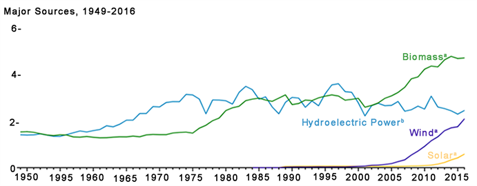
Figure 1. Renewable energy consumption (quadrillion Btu) in the United States [2] .
The purpose of the research in this paper is twofold. The first is to thoroughly present the different attributes of multigeneration and all of its associated benefits. Multigeneration design requires knowledge of multiple disciples to understand all of the potential components and how they operate together. The most basic form of multigeneration is combined heat and power, often called cogeneration, and for this reason the paper will outline power and thermal generation as well as waste heat recovery. It also briefly provides a breakdown of the desalination methods, with particular focus on multi-stage flash distillation. The second objective is to determine the feasibility of a proposed small scale multigeneration desalination system by experimental and numerical methods. The performance characteristics, the electricity generated, the fresh water produced per kW and the overall plant efficiency is presented.
2. Multigeneration
Multigeneration in this paper is defined as any system capable of producing energy in two or more different forms from one or more power sources. The concept of multigeneration has been in practice since nearly the beginning of electrical power generation. One plant, known as the Pearl Street Plant, was built in 1882 and simultaneously produced electrical power and district heating for lower Manhattan [5] . Multigeneration systems, however, are not only expensive to install but also to maintain and thus it is important to understand where multigeneration should be considered practical and when it is impractical. Typical applications for multigeneration include: 1) Hotels or large apartment complexes; 2) Casinos; 3) Large office buildings; 4) Airports; 5) Hospitals; 6) Manufacturing; 7) Desalination. In most cases, multigeneration makes sense if and only if the system is allowed to produce power uninterrupted and if the site maintains a certain load. If there is no thermal load, or if that load is inconsistent over time, then multigeneration producing electricity and heat should not be considered.
Multigeneration is basic in concept but complicated in design, details, and integration. It is also flexible, allowing for numerous configurations and power sources. The main equipment of multigeneration systems that produce useable electrical power and heat consist of a power source, a generator, and a heat exchanger. The specific generator and heat exchanger implemented depends primarily on the desired load and output, the climate of the particular site, and any specific applications or production goals. For this reason, the main power sources of this production are first outlined, following heat exchanger and multigeneration design characteristics, and finally the desalination.
2.1. Power and Thermal Generation
Gas turbines, have a high power-to-weight ratio while operating with simple cycle configurations, and thus are popular in the industrial production of energy. Turbines are capable of producing extremely hot exhaust gases that can reach temperatures upwards of 1000 ˚F, which makes them ideal for multigeneration systems looking to capture heat. Also they are relatively low-maintenance which can help lower operation costs by reducing the overall capital cost to produce power. Conventional turbines, as load following, experience a longer lag time to ramp up or down when compared to reciprocating engines. Micro-turbines, however, allow for quicker ramp up time and the flexibility to shutdown individual micro-turbines when in energy saving mode. For this reason, a micro-turbine is selected in this multigeneration system.
Reciprocating engines, can run on natural gas, diesel, gasoline, and biogas. They also do well in most climates, making them advantageous in remote areas with fluctuating weather when compared to turbines. Many cogenerations already in operation are powered by reciprocating engines. Caterpillar, Inc. produces a series of generators designed for multigeneration use. Princeton University installed a G3520E generator set to provide steady power and heating for their High-Performance Resource Center [6] . Reciprocating engines are considered to be competitive power generators for multigeneration.
Fuel cells, essentially batteries, can provide efficient, clean power and integrate well into multigeneration systems. They are suitable for smaller or medium sized projects. Better fuel cell designs are constantly being developed with increased efficiencies, cheaper materials, and even different functions. One company, FuelCell Energy, invented a fuel cell capable of capturing carbon dioxide from the exhaust gases of a coal plant and then using it as a fuel source to create electricity. Out of various fuel cells, Solid oxide fuel cell (SOFC) stands out in terms of generating a great amount of heat with typical operating temperatures from 800˚C to 1000˚C. It can produce 2 MW of electricity at a 60 percent efficiency [7] while many other fuel cell stacks can only generate upwards of 300 kW. Due to its high heat rate and greater scale, the SOFC makes an excellent candidate for multigeneration.
2.2. Heat Exchanger and Waste Heat Recovery
Heat exchangers are essential to almost any multigeneration system where the heat that is rejected from the generator, whether by ambient, water jacket, or exhaust gases, is diverted to pass through a heat exchanger to make use of that energy. One design of heat exchanger is known as exhaust steam generators where steam is created from deaerated water and hot exhaust gases. Most exhaust steam generators are shell and tube heat exchangers due to the high pressure involved. Deaerated water is pumped through a network of tubes and the exhaust gases heat the fluid as they pass through the shell which houses all the tubes. Another design is known as a plate heat exchanger, which uses multiple, thin plates stacked in series with each other. The plates can be made with different materials, textures, and arrangements depending on the application. They work well for fluid to fluid heat transfer if there are multiple loops with different fluid types in a system. The hot water that is generated can be used to supply a hot water loop for a building or an absorption chiller loop for air-conditioning a building.
Heat exchangers in multigeneration systems can modulate the amount of exhaust depending on the required load via a sensor-controlled damper. Sensors monitor temperature and flow rates of the steam or hot water leaving the heat exchangers. The efficiency of the heat recovered from a generator begins with the heat exchanger design and appropriate sizing, and then relies on the sophistication of the instrumentation control.
Heat exchangers also play a key role in external waste heat recovery technologies once wasted thermal energy is identified and converting waste heat into usable energy is feasible. Perhaps the most used external waste heat recovery method is to generate steam from deaerated water by absorbing the thermal energy within exhaust gases. The heat exchanger used to accomplish this is known as a heat recovery steam generator (HRSG). An alternative method is to utilize the exhaust gases to directly transfer heat into its destination which is adopted in the current design.
To increase the efficiency of power generating systems, one promising piece of equipment that may be used much more with multigeneration systems in the future is an organic Rankine cycle (ORC). The organic Rankine cycle should not be considered a power source for multigeneration systems since it simply transforms thermal energy into mechanical work, and ultimately electrical power. There are many interesting applications for ORC’s within multigeneration configurations, and there has been continued research to improve efficiencies over the years [8] [9] . The applications for ORCs in multigeneration include biomass which is converted into gas, or lower temperature exhaust gases from turbines or reciprocating engines that may have already passed through an exhaust steam generator. As the technology for organic Rankine cycles becomes more economical, these devices will be used more in multigeneration systems.
In addition to external waste heat recovery, internal recuperation is another method to recover waste heat from a power source by scavenging the heat back into the system and to increase the overall efficiency of the power source as well. For example, the simple Brayton cycle of a turbine and a compressor is coupled with regeneration (or internal recuperation), where the exhaust gases rejected from the turbine are used to preheat the air after the compressor but before combustion. This will allow for less required energy to ignite the fuel source thus increasing the electrical efficiency of the unit. However, internal recuperation is utilized only when the efficiency of the electrical output is required or beneficial. In some cases, especially with multigeneration, it is not beneficial to boost the electrical efficiency since the thermal demand may be of greater significance. Under those conditions, external recuperation, rather than internal, would be implemented [10] .
2.3. Multigeneration Design Characteristics
Multigeneration systems are very diverse, offering solutions to many problems. The design of this system is dependent on the location of the site and its climate, the demand size, the level of grid independence required, and the specific energy forms desired. These multigeneration design characteristics are discussed in the following subsections.
2.3.1. Climate and Load Sizing
In a multigeneration design, the total energy demand for the site must be established. For example, a large hotel located in Northern Canada may have a high, consistent electrical demand as well as a high heating demand for most of the year, which would make it a great candidate for combined heat and power. If that hotel is located in a climate with extreme temperatures then trigeneration would be the ideal solution. During hot summers the building’s cooling demand will be great, and during cold winters the heating demand will be great as well. If a trigeneration system (producing electricity, heat, cold) is designed appropriately with a heat exchanger and an absorption chiller then the system can adapt for each season to maintain an overall higher efficiency. However, that same size hotel in Miami, Florida may not have enough thermal load year round with its mild climate changes for combined heat and power to make sense economically. Climate on site is clearly a crucial factor to be considered for the design.
2.3.2. Uninterrupted Power Supply
Multigeneration system is reliable to supply the power due to its onsite power production. Typical back up power installations have a delay from the time when a power outage occurs and when the generator, usually diesel, gets up to speed to supply power to the building. This delay can cause dramatic consequences even if the delay is only seconds long. At a manufacturing plant for example, if a time sensation ingredient is being used and there is a power outage, the entire batch of the product is often discarded, costing the manufacturer time and money. Data loss is another major concern when a server goes down from a power outage. At a large hospital for another example, this delay could put hundreds of lives in danger. In most cases, a diesel generator is used as an emergency backup to run in the event of a power outage but they are very expensive to maintain and run [11] . With such a high cost and critical function, backup diesel generators do not present an adequate solution to the problem. With multigeneration power installed onsite, a hospital or manufacturing plant can experience uninterrupted power even when the utility loses power. The switchgear can be designed to seamlessly transfer the building load solely onto the multigeneration unit or units, which are designed to run continuously.
2.3.3. Onsite Specialty Equipment
One interesting and diverse area of focus in advanced multigeneration power systems is site specific, or specialty equipment. Specialty equipment may be used to increase efficiency and production at a particular site, to create more stable power, or to manufacture specific products. Manufacturing equipment, in particular, presents many potential designs that could be incorporated into a multigeneration system since it often requires heat for certain processes. For example, a basic cogeneration system using a reciprocating engine to generate electricity and heat could be coupled with some type of specifically designed heat fan, powered by the exhaust gases, to remove moisture from a farmer’s crop. A desalination plant could be designed and built in conjunction with a power plant to generate electricity, heat, and fresh water. In these cases, the heat fan and desalination equipment are specifically designed for multigeneration use and are therefore part of the system.
To provide onsite, stable, and consistent electricity, multigeneration systems can make use of a rotary uninterruptible power supply, or RUPS. These devices, essentially massive electrical flywheels, can ramp up to absorb excess electricity or ramp down to release mechanical energy back into electricity. Facilities such as data centers frequently use RUPS to control any fluctuations in power that could damage or reduce the performance of their servers. Also hospitals or certain types of manufacturing that cannot afford to lose power for any time period can integrate RUPS into a multigeneration system to ensure constant power. The application for this technology has hardly been implemented or studied.
In regards to total efficiency, many advanced multigeneration systems must be designed with specialty equipment that meets the desired demands. This highlights the importance of understanding the applications and limits of multigeneration systems.
2.3.4. Resource Production
Resources are typically gathered from nature but they cannot sustain our large and ever growing infrastructure and even our fresh water demand cannot be met everywhere in the world. Consequently, fuels are synthesized and food is processed on a massive scale. The production of valuable resources is an expensive and yet crucial industry. Multigeneration systems have been proposed to not only produce electricity and heat, but also synthetic fuels, pure hydrogen, and fresh water. These plants represent the sophisticated potential of the multigeneration concept, and similar concepts have already been put into practice.
One intriguing multigeneration system that was built in September 2008 is located about 50 kilometers north of Amsterdam in the Netherlands. The Royal Pride Holland Facility, one of the largest commercial tomato greenhouses, installed two of GE Energy’s 4 MW natural gas-fueled J624 GS engines to produce electricity, heat, and CO2 used to increase crop productivity. They are able to reduce the emissions from their power plant to nearly zero by diverting the remaining exhaust gases into the greenhouses instead of into the atmosphere. The entire system operates at a 95 percent efficiency since almost all the energy put in is consumed within the system [12] .
It is clear that multigeneration systems are the future of resource production and manufacturing processing, where electrical power is generated locally and energy efficiencies are high.
2.4. Desalination
Commercial desalination began at the beginning of the 20th century. It is most commonly seen around the Middle-East and North Africa, around 50% of worldwide desalting capacity, where there are highly populated cities and the surrounding lands are mostly desert [13] . Desalination plants have been historically expensive and inefficient as a source of fresh water, yet in many cases desalination is the only solution. To make desalination more feasible and efficient, power generating configurations can be integrated into the system; such as steam turbine plants, gas turbine plants, or combined cycle power plants.
Desalination can be accomplished by a number of different methods. Reverse osmosis (RO) and mechanical vapor compression (MVC) only require electrical power and therefore do not utilize the rejected heat energy from power plants. Multi-stage flash (MSF) distillation, which typically has the worst thermodynamic efficiency, can utilize the waste heat from a power plant to convert saltwater into freshwater.
Multi-stage flash (MSF) distillation operates by reducing the pressure of each stage to the level below the saturation pressure of the corresponding fluid temperature and therefore a portion of the fluid will “flash” into steam upon entry. The optimum configuration for any MSF plants depends on parameters such as thermal heat source capacity, number of stages, fresh water demand, maximum brine blowdown salinity, seawater source salinity, and any financial constraints. A typical MSF plant configuration is depicted in Figure 2. The plant is made broken into three categories: the heat input, heat recovery, and heat rejection.

Figure 2. Summary of multi stage flash (MSF) distillation calculation results.
Outside of the flashing stages there is a brine heater, or heat exchanger, which is the heat input section. Steam is usually the heat source which is transferred through the heat exchanger. In the present study the exhaust gases from a micro-turbine will be the heat source. Heat recovery section typically contains 21 - 40 stages according to El-Dessoukey [14] . Each stage has three individual streams flowing through it: the recycled brine (first pass), the fresh water distillate, and the recycled brine (second pass). The heat rejection section typically contains 2 - 3 stages in which the make-up seawater and the cooling seawater circulate through the condensers to absorb the remaining thermal energy originally produced in the heat input section. The cooling seawater is pumped back to the sea and the make-up water is preheated before mixing with the recycled brine. Each stage in the heat recovery and heat rejection section contains a tube bundle or condenser, demister, brine orifice, distillate tray, and a vent line. There are pumps that control the flow rate of each separate stream and there is instrumentation to read and communicate for proper function of the system. In this study, multi-stage flash (MSF) was selected in the multigeneration system for its cost effectiveness and versatility.
3. Proposed Design and Numerical Analysis
3.1. Literature Review
A few advanced multigeneration power systems were recently designed and analyzed with promising results that shed light on the future of multigeneration power. The concept shared throughout these designs is the idea of producing a useable resource while simultaneously generating electricity and useable heat. Two of the systems were proposed and analyzed by Eda Cetinkaya [15] and another was proposed and analyzed by Naterer, Dincer, and Zamfirescu [16] . Shafaghat and Kotb studied the optimum design for multi-stage flash (MSF) desalination coupled with power plants of 42 MW and 650 MW respectively [17] [18] . Finally, Jammoul and El-Samni investigated the design and benefits of a small scale MSF desalination unit driven by the exhaust of diesel generators [19] . The last three studies are used to validate the proposed design in this paper and a comparison analysis will yield a better understanding the challenges for small scale multigeneration.
Due to recent advances in the thermochemical water-splitting cycles, Zamfirescu proposed a system that integrates nuclear power production with the ability to convert water into pure hydrogen and oxygen. Back in the 1970’s the Gas Research Institute and General Atomics in the USA identified a number of thermochemical cycles for water splitting and then again attention was renewed in 2003 at the Argonne National Laboratory.
In 2013, Cetinkaya investigated the theoretical efficiencies of two trigeneration systems. The first system utilizes two power cycles (steam Rankine cycle and organic Rankine cycle) and a key process (desalination). Its energy source is solar radiation, which is collected by a solar power tower system, producing electricity, hot water, and fresh water. This system was designed by Cetinkaya for remote, undeveloped coastal regions, to mainly provide fresh water and electricity. Cetinkaya analyzed a second system in the same theoretical study. It utilizes three power cycles (Brayton cycle, steam Rankine cycle, and organic Rankine cycle) and two key processes (gasification and Fischer-Tropsch synthesis). And its energy source is coal and biomass converted into a gas which is then burned in a turbine to produce electricity, hot water, and synthetic fuel. Cetinkaya investigated two types of coal in an experimental set-up (Tunçbilek-Ömerler and Konya-Ilgın) and one type of biomass (wheat straw) for the gasification process. She found that Konya-Ilgın coal yielded a higher amount of hydrogen in the synthesis gas composition. The organic Rankine Cycles (ORCs) utilized in each system were analyzed for three different configurations and altering fluids to maximize efficiency and power output. Cetinkaya found that when comparing the two trigeneration systems, the synthetic fuel system was more efficient in terms of both energy and exergy.
3.2. Proposed Design
The proposed multigeneration system is a combined power and desalination plant. Waste heat from power plants is used as a source of energy for desalination. The cost for the heat supply to desalination and the cost of running condensers will be reduced. Figure 3 shows the schematic of proposed multigeneration system.
Power Source: This multigeneration system utilizes experimental data collected from five gas micro-turbines, each consisting of a compressor, combustion chamber and in this case a recuperator, to produce power and thermal energy in the form of exhaust gases. Each micro-turbine is capable of producing 200 KW of power and the entire output of the system was measured to be 944 KW at ambient air temperature of 61 ˚F. The de-rate factor was calculated to be as 112 KW with the decline beginning around 74 ˚F. Backpressure can cause both losses in power and efficiency of micro-turbines. As the backpressure increases, both power and efficiency are decreased gradually. The exhaust produced from the micro-turbines flowed at a rate of 14.4 pounds per second and carried thermal energy in the amount of 6,713,000 Btu per hour. The recorded

Figure 3. Schematic of proposed multigeneration design.
average exhaust temperature was 579 (˚F). To produce this amount of electrical and thermal energy the natural gas energy input into the turbine was 10,599,000 Btu per hour. Making the overall efficiency of the micro-turbines to covert the energy within natural gas into electrical power 30.4%.
Heat Exchanger: The purpose of this study is to analyze the scaling effect of multigeneration desalination, and one of the most effect ways of reducing cost and maintenance of a system is to reduce the number of individual components. For this reason, steam is not produced from a heat recovery steam generator (HRSG), but rather the thermal energy stored in the exhaust gas is then diverted into a heat exchanger where the other fluid is the recycled brine stream of the multi-stage flash (MSF) desalination unit. It was calculated that a shell and tube heat exchanger could be designed to successfully transfer 3,894,804 Btu per hour from the exhaust gas and into the recycled brine. That amount of energy is required to heat the recycled brine (first pass) leaving the first stage at 170 (˚F) up to the top brine temperature (TBT) of 190.4 (˚F). This yielded an overall thermal efficiency of the plant to be 36.8%.
Desalination: The multi-stage flash distillation unit that is powered by the exhaust gases from the micro-turbines was sized according to the numerical analysis done in Section 3.3.2. It was determined that 10 stages was the ideal number due to sizing limits for this application and cost impact.
Evaporative Production of Salt: The final stage of the proposed multigeneration design is the production of salt through natural evaporation by solar radiation and wind convection. This system was sized accordingly to take advantage of the calculated brine blowdown mass flow rate that is typically pumped back into the sea. In this case, however, the brine blowdown is pumped into shallow salterns, or solar ponds, where the remaining water is converted into vapor leaving behind salt.
3.3. Numerical Analysis
In the present study, multigeneration is where natural gas fuel is converted into exhaust heat and mechanical energy. The mechanical energy is then converted into electricity by a generator. The exhaust energy is transferred into the recycled brine which produces fresh water available for consumption. Finally, the brine blowdown is converted into salt by utilizing the natural evaporation of water from solar radiation and wind convection. It is important to understand the equations governing the proper design of a multigeneration system, which will be described in the following subsections.
3.3.1. Climate and Load Sizing
For a multi-stage flash distillation unit, it needs to determine the optimum temperatures, flow rates, and sizes. The numerical analysis presented below is based on a set of industry standard assumptions that do not significantly impact the results [19] . The following assumptions are made:
1) The fresh water produced by condensation is completely salt free;
2) Any subcooling of condensate or superheating of vapor is considered negligible on energy balance;
3) The heat transfer areas for each stage are equal for manufacturing and cost purposes;
4) The losses associated with the power required for pumps and other auxiliaries not considered;
5) The heat losses from surroundings are considered negligible to energy balance.
Mathematical representation of brine heater: The brine heater is determined to be a shell and tube heat exchanger and its energy balance is given as
(1)
where Cp is the specific heat at constant pressure, T is the temperature, and the subscripts gas, o, i, 1, denote the exhaust gas from the micro-turbines entering and exiting, brine stream entering the heat exchanger, and brine stream exiting the heat exchanger, respectively. The heat transfer rate for the brine heater is given as
(2)
(3)
where U is the overall heat transfer coefficient for the heat exchanger, A is the heat transfer area, LMTD is the log mean temperature difference, and the subscript bh denotes brine heater.
Mathematical representation of condenser: The heat transfer rate equation for the condenser is given as
(4)
(5)
where U is the overall heat transfer coefficient, A is the heat transfer area, LMTD is the log mean temperature difference, and the subscripts c and v denote the condenser and the flashing vapor respectively.
Mathematical representation of mixing in final stage: The final stage is where the make-up feedwater (Mf) is mixed with the recycled brine flow (Mr), and where the fresh water distillate (Md) and the brine blowdown (Mb) flow out of the system. Using the principles of continuity, energy balance, and heat transfer equations the following equations are derived. The mass balance and salinity balance yield
(6)
(7)
where M is mass flow rate in pounds per hour, the subscripts f, b, and d denote make-up feedwater, brine blowdown, and fresh water distillate respectively, and X is the salt concentration in ppm. The energy balance for the final stage includes the cooling water (Mcw) which, along with the make-up feedwater (Mf) passes through the condenser absorbing the heat from the water vapor. The energy balance and salinity balance are given as
(8)
(9)
(10)
where the subscript cw and r denote the cooling water and the recycled brine water respectively.
Mathematical representation of each stage: Due to the changing salinity of the recycled brine in each stage as more fresh water is produced, the specific heat is given as [11]
(11)
(12)
(13)
(14)
(15)
where T is the temperature of the recycled brine in each stage, and S is the salinity level of the recycled brine in g/kg. The total summation of the distillate product gathered in all the stages is given as
(16)
where n is the number of stages and y is the specific heat ratio of sensible heat given as
(17)
where λav is the average latent heat calculated at the average temperature, Tav given as
(18)
3.3.2. Combined Cycle
In a combined cycle cogeneration design the net power that is produced equals the sum of all the power within the system as denoted in Equation (19). This includes: gas turbine power output (positive), compressor power input (negative), steam turbine power output (positive), and pump power input (negative) [20] .
(19)
The heat recovery is calculated by the heat rejected from the exhaust in the condenser and is shown as
(20)
For the proposed multigeneration design, it does not incorporate a steam turbine, but instead utilizes a shell and tube heat exchanger to reject the heat from the exhaust gases directly into the recycling brine water. Equation (19) then becomes Equation (21) for determining the work done by the micro-turbines,
(21)
where the work done by the steam turbine is removed and work done by the pump is disregarded to simplify the calculations. The losses for the entire plant are estimated at 6.2%, which include thermal, mechanical, and any transmission losses.
3.3.3. Heat Exchanger
The heat exchanger, or the brine heater for the desalination unit, was selected to be a shell and tube heat exchanger.
(22)
3.3.4. Evaporative Production of Salt
The final stage of this multigeneration system is the evaporation and harvesting of salt as the byproduct of the brine blowdown. From Equation (10) we know the mass flow rate of the brine blow down Equation (23). And the equation for estimating evaporative heat flux from shallow solar ponds is given as Equation (24) [21] ,
(23)
(24)
where C is the geometric constant, which is estimated as 0.5 for shallow waters. P3 is the partial pressure of water vapor in air measured in mmHg and V3 is the velocity of wind in mph
(25)
(26)
where c1 is the salt concentration level, which is equal to the brine blowdown salinity (Xb), and T is the temperature of the brine blowdown exiting the multi-stage flash (MSF) unit. To determine the area required for total evaporation, the evaporative heat flux, Equation (24) was set equal to the mass flow rate of the brine blowdown Equation (23) divided by area, therefore Equation (27),
(27)
Therefore the amount of surface area required to evaporate the water vapor is dependent on the velocity of the wind. The calculations for determining the acreage required also include accounting for only an average of 8 hours of adequate sunlight while the brine blowdown flow rate is assumed 24 hours a day.
4. Results and Discussion
4.1. Results Summary
The overall efficiency of the multigeneration system was calculated to be 67.8%. That is the sum of the efficiency of the micro-turbine to convert natural gas energy into electrical power 30.4% and the amount exhaust gas energy needed to produce fresh water relative to the initial natural gas energy 36.8%. The remaining exhaust gas energy accounts for 26.6% of the system, and the thermal, electrical, and mechanical losses within the system were estimated to be 6.2%. This data was calculated from the numerical analysis presented in Section 3.3 and is summarized in Table 1.
In Table 2, the temperature values of the recycled brine within each stage, the first and second pass, are presented. The temperature drop in each stage is 10.2 (˚F), the intake seawater temperature was estimated to be 68 (˚F), and the top brine temperature (TBT) was set to 190.4 (˚F).
Figure 2 shows a summary of the calculated flows, salinity levels, and temperatures within the desalination process of the multigeneration system. This data was calculated from the numerical analysis presented in Section 3.3.1.
The specific heat and the latent heat were calculated for each stage and the results are presented in Table 3.
The calculated flows and salinity level are presented in Table 4. As expected, the brine salinity increases at each stage since the mass flow rate of the brine is decreasing. The total flow rate within the heat recovery section is equal to the recycled brine flow rate (Mr) which was determined by Equation (1). That flow rate is equal to the sum of the distillate flow rate (Md) and the brine flow rate (Mb) at each stage.
The proposed design is capable of producing around 1 MW of electrical power, 56,891 gallons/day of fresh water, and 4.07 tons/day of sea salt. A summary of calculated key design parameters is presented in Table 5.

Table 1. Proposed multigeneration desalination system efficiencies.
Table 2. Temperature values for recycled brine within each stage.
Table 3. Specific heat and latent heat within each stage.
Table 4. Calculated data of flow rates and salinity level for each flashing stage.
Table 5. Summary of calculated data of design parameters for proposed multigeneration system.
4.2. Validation
To validate the results of this study, research from three previous designs will be compared. The purpose will be to evaluate the scaling of multigeneration desalination plants in regards to the amount of fresh water produced per kilowatt of power produced.
In 2012, Shafaghat proposed a multi stage flash (MSF) desalination design that was powered by a 42 MW combined cycle power plant that produced 10 tons per hour of steam. The total fresh water production was calculated to be 2480 tons per day, the gained output ratio was 10.3, and the optimum number of flashing stages was determined to be 24 [17] .
In a similar study done by Kotb, an optimum numerical approach was presented for design a multi-stage flash (MSF) desalination plant powered by a 650 MW combined cycle plant. It was determined the power plant could deliver up to 1528 tons per hour of steam from the low pressure section of a heat recovery steam generator. The MSF desalination was numerically analyzed and the mass flow rate of the fresh water distillate was calculated to be 8845 tons per hour, the GOR was 8.76, and the number of flashing stages was 28 [18] .
Both studies represent multigeneration desalination on a larger scale, whereas, the study done by Jammoul and El-Samni was focused on a small scale MSF desalting unit powered by the exhaust gases of diesel generators. The analysis was conducted on generators ranging from 7.2 KW to 1267 KW of electrical power. It was concluded that the amount of freshwater produced by a diesel generator could be estimated by the second order polynomial as 0.36 + 2.7 × 10⁻³ (kVA) + 3.1 × 10⁻⁶ (kVA)2 [19] .
Table 6 shows the values determined in the other case studies and validates the proposed small scale multigeneration desalination design as a viable option for producing power and fresh water. While the freshwater produced per kW is higher for the diesel generator, the low installation and operation costs of the proposed design may offer a more realistic approach to small scale power, freshwater, and salt production.
5. Conclusions
Multigeneration power systems represent an intelligent and realistic way to address our increasing energy problem [22] [23] [24] . The demand for energy and fresh water continues to increase while the need to reduce emissions increases as well [25] [26] . This project has analyzed the feasibility of a smaller scale multigeneration desalination power plant. The proposed design is capable of producing around 1 MW of electrical power, 56,891 gallons/day of fresh water, and 4.07 tons/day of sea salt. Compared to similar designs, the proposed design has a lower performance ratio (i.e., power output divided by fresh water produced) while its size and simplicity make it a more feasible financial option.
Table 6. Comparison of performance with previous studies on multigeneration desalination system.
Multigeneration systems typically have total efficiencies from 65 percent to 90 percent, while most conventional power generation is usually around 30 to 40 percent. Typical generators include turbines, reciprocating engines, or fuel cells, which are integrated with heat exchangers to utilize the rejected heat. The applications for multigeneration include buildings with large electrical and thermal loads, facilities that need uninterrupted power, certain manufacturing plants and desalination.
There is now an increased demand for local, more efficient power production and there will be increased research and development focused on multigeneration systems. The development of more sophisticated control schemes will allow for higher precision when trying to meet set points and the ability to create better overall designs. Further research and simulation could be done for multigeneration desalination especially in regards to the heat exchanger design and the multi-stage flash (MSF) plant design. The next step would be to run computational fluid dynamic (CFD) software to simulate the heat transfer of different design parameters. The exhaust gas to recycled brine shell and tube heat exchanger could be optimized for small scale multigeneration.
Another interesting subject that deserves further investigation is the creative utilization of the brine blowdown from the MSF plant. In this study, the brine was pumped into shallow salterns, or salt ponds, to be naturally evaporated by radiation from the sun and convection from the wind, however, there may be other uses for the high salt concentrated brine. One potential use could be to stimulate growth of certain algae that thrive in brine saltwater. Oren studied multi-pond solar salterns as the primary process for a highly diversified biological system [27] .
The goal of this study was to analyze a smaller scale multigeneration system, however, more research should be done at the residential scale. Micro-multigeneration desalination plants could provide electrical power, heat, air-conditioning and freshwater for off-the-grid homes on any coast line in the world. The associated cost for such a system presents perhaps the largest deterrent for production.
Acknowledgements
The research project was partially supported by 2016-2017 Research & Creative Activity (RCA) Faculty Awards Program at California State University, Sacramento, USA.
Cite this paper
Pleis, J.R. and Zhou, D.M. (2017) Numerical and Experimental Study of a Multi-Generation Desalination Power Plant. Journal of Power and Energy Engineering, 5, 172-192. https://doi.org/10.4236/jpee.2017.59014
References
- 1. United Nations (2017) World Population Prospects, Key Findings & Advance Tables. https://esa.un.org/unpd/wpp/Publications/Files/WPP2017_KeyFindings.pdf
- 2. US Energy Information Administration (2017) Figure 10.1. Monthly Energy Review. http://www.eia.gov/totalenergy/data/monthly/pdf/mer.pdf
- 3. Allan, J.A. (2002) The Middle East Water Question. I. B. Tauris Publishers, London and New York.
- 4. Zotlis, K., Dialynas, E.G., Mamassis, N. and Angelakis, A.N. (2014) Desalination Technologies. Water, 6, 1134-1150. https://doi.org/10.3390/w6051134
- 5. Monaco, A. (2011) Edison’s Pearl Street Station Recognized with Milestone. The Institute.
- 6. Caterpillar, Inc. (2013) CAT G3500 Series Gas Generator Sets Brochure. April 2013.
- 7. Smithsonian Institution (2008) Fuel Cell Basics.
- 8. Xiaoze, D. (2015) Characteristics of Organic Rankine Cycles with Zeotropic Mixture for Heat Recovery of Exhaust Gas of Boiler. Energy Procedia, 75, 1093-1101.
- 9. Villarini, M. and Bocci, E. (2014) State of Art Small Scale Solar Powered ORC Systems: A Review of the Different Typologies and Technology Perspectives. Energy Procedia, 45, 257-267.
- 10. Carapellucci, R. and Giordano, L. (2014) The Recovery of Exhaust Heat from Gas Turbines, Efficiency, Performance and Robustness of Gas Turbines. InTech.
- 11. Bloomberg Business Technology (2012) How to Keep a Generator Running When You Lose Power.
- 12. Power Business and Technology for the Global Generation Industry (2009) Top Plants: Royal Pride Holland Commercial Greenhouse Cogeneration Plant. Middenmeer, North Holland Province.
- 13. Gudmundsson, J. (2012) Use of Natural Gas to Produce Power and Fresh Water. Norwegian University of Science and Technology. Trondheim.
- 14. El-Dessoukey, H. and Ettouney, H. (2002) Fundamentals of Salt Water Desalination. Elsevier, Amsterdam, New York.
- 15. Cetinkaya, E. (2013) Experimental Investigation and Modeling of Integrated Tri-generation Systems. Thesis, University of Ontario Institute of Technology.
- 16. Naterer, G.F., Dincer, I. and Zamfirescu, C. (2013) Hydrogen Production from Nuclear Energy. Springer Science & Business Media. https://doi.org/10.1007/978-1-4471-4938-5
- 17. Shafaghat, R. (2012) Design of a MSF Desalination Plant to be Supplied by a New Specific 42 MW Power Plant Located in Iran. World Academy of Science, Engineering and Technology, 6, 463-469.
- 18. Kotb, O.A. (2015) Optimum Numerical Approach of a MSF Desalination Plant to Be Supplied by a New Specific 650MW Power Plant Located on the Red Sea in Egypt. Ain Shams Engineering Journal, 6, 257-265.
- 19. Jammoul, R. and El-Samni, O.A. (2015) Design of a Small Scale Multi-Stage Desalination Plant Driven by the Exhaust of Diesel Generators. Mechanical Engineering Department, Beirut Arab University, and Alexandria University.
- 20. Arnas, A.O.A., Boettner, D.D., Norberg, S.A., Tamm, G. and Whipple, J.R. (2009) On the Teaching of Performance Evaluation and Assessment of a Combined Cycle Cogeneration System. Journal Energy Resource Technology, 35-42. https://doi.org/10.1115/1.3124114
- 21. Diaz, R., Stewart, S. and Brownson, J. (2012) Use of Concentrated Solar Thermal Energy Systems to Enhance Sea Salt Production in Southern Spain. The Pennsylvania State University.
- 22. Dubey, M. (2014) Review on Waste Energy Recovery Systems. International Journal of Innovative Research in Science, Engineering and Technology, 3, 18356-18367.
- 23. Chua, K.J., Yang, W.M., Wong, T.Z. and Ho, C.A. (2012) Integrating Renewable Energy Technologies to Support Building Trigeneration—A Multi-Criteria Analysis. Renewable Energy, 41, 358-367.
- 24. Pleis, J.R. (2015) Experimental and Numerical Investigation of a Multigeneration Desalination Power Plant. Thesis, California State University, Sacramento.
- 25. Hamed, O.A. (2005) Overview of Hybrid Desalination Systems—Current Status and Future Prospects. Desalination, 186, 207-214.
- 26. El-Dessouky, H., Ettouney, H., Al-Juwayhel, F. and Al-Fulaij, H. (2004) Analysis of Multistage Flash Desalination Flashing Chambers. Chemical Engineering Research and Design, 82, 967-978. https://doi.org/10.1205/0263876041580668
- 27. Oren, A. (2009) Saltern Evaporation Ponds as Model Systems for the Study of Primary Production Processes under Hypersaline Conditions. Aquatic Microbial Ecology.