Paper Menu >>
Journal Menu >>
 Engineering, 2010, 2, 103-106 doi:10.4236/eng.2010.22014 Published Online February 2010 (http://www.scirp.org/journal/eng). Copyright © 2010 SciRes. ENGINEERING Analytic Computation Method of the Equivalent Thickness of Superposition Multi-Throttle-Slices of Twin-Tubes Shock Absorber Changcheng Zhou, Yingzi Xu School of Transport and Vehicle Engineering, Shandong University of Technology, Zibo, China E-mail: greatwall@sdut.edu.cn Received August 27, 2009; revised September 22, 2009; accepted October 4, 2009 Abstract By elastic mechanics, the deformation of single throttle-slice for shock absorber was analyzed, the formula of its deformation was established. According to the relation of the deformation of multi-throttle-slices with the pressure on each slice, the analytic formula of equivalent thickness of multi-throttle-slices was established. Followed is a practical example for the computation of the equivalent thickness of multi-throttle-slices, com- pared the computed results with that simulated by ANSYS. The results show that the computation method of equivalent thickness of multi-throttle-slices is accurate enough. Keywords: Twin-Tubes Shock Absorber, Multi-Throttle-Slices, Equivalent Thickness, Analytic Computation 1. Introduction With the improvement of automobile technology, the velocity also improves, and there is a higher request to the smoothness and the security [1,2]. The characteristic of shock absorber influences driving smoothness and secu- rity of vehicles, nevertheless, it depends on the quality of the design and manufacture of shock absorber [3]. The telescopic twin-tubes shock absorber is widely used for vehicles. Nevertheless, it is still a puzzling problem for the throttle valves parameters design to calculate accu- rately the equivalent thickness of muti-throttle-slices. At present, both in domestic and abroad, in despite of many scholars analyzed the computation of equivalent thickness of multi-throttle-slices mostly by the finite element methods, they given out some qualitative conclusions only. This situation is un-accommodated to highly devel- oped technology of automobile and affects the design quality of shock absorber. For the parameters design of throttle valves, there is not any analytic method yet, only with the experience of designer, testing and modification repeatedly [4,5]. It is said that the design for parameters of multi-throttle-slices, firstly a parameter value is guess- timated on experience, then testing and modification time and again; at lastly, the design value is fixed. While one parameter changing, other parameters would also change. Therefore, this method is inaccurate, the parameters of multi-throttle-slices could not been designed reliably. The traditional method of the equivalent-thickness of multi-th- rottle-slices is only a numerical simulation value [6,7], but it is unable to offer an analytic formula used to design the parameters of multi-throttle-slices. In this paper, the analytic computation method of equivalent thickness of multi-throttle-slices was resear- ched, the formula of equivalent thickness was established, and the results computed were tested with software ANSYS. 2. Deformation of Single Throttle-Slice 2.1. Mechanics Model of Single Throttle-Slice Figure 1 is the mechanics model of elastic throttle slice. The boundary conditions of throttle slice are fixation restriction at the inner radius, and free restriction at the outer radius. Figure 1. Mechanics model of elastic throttle-slice. 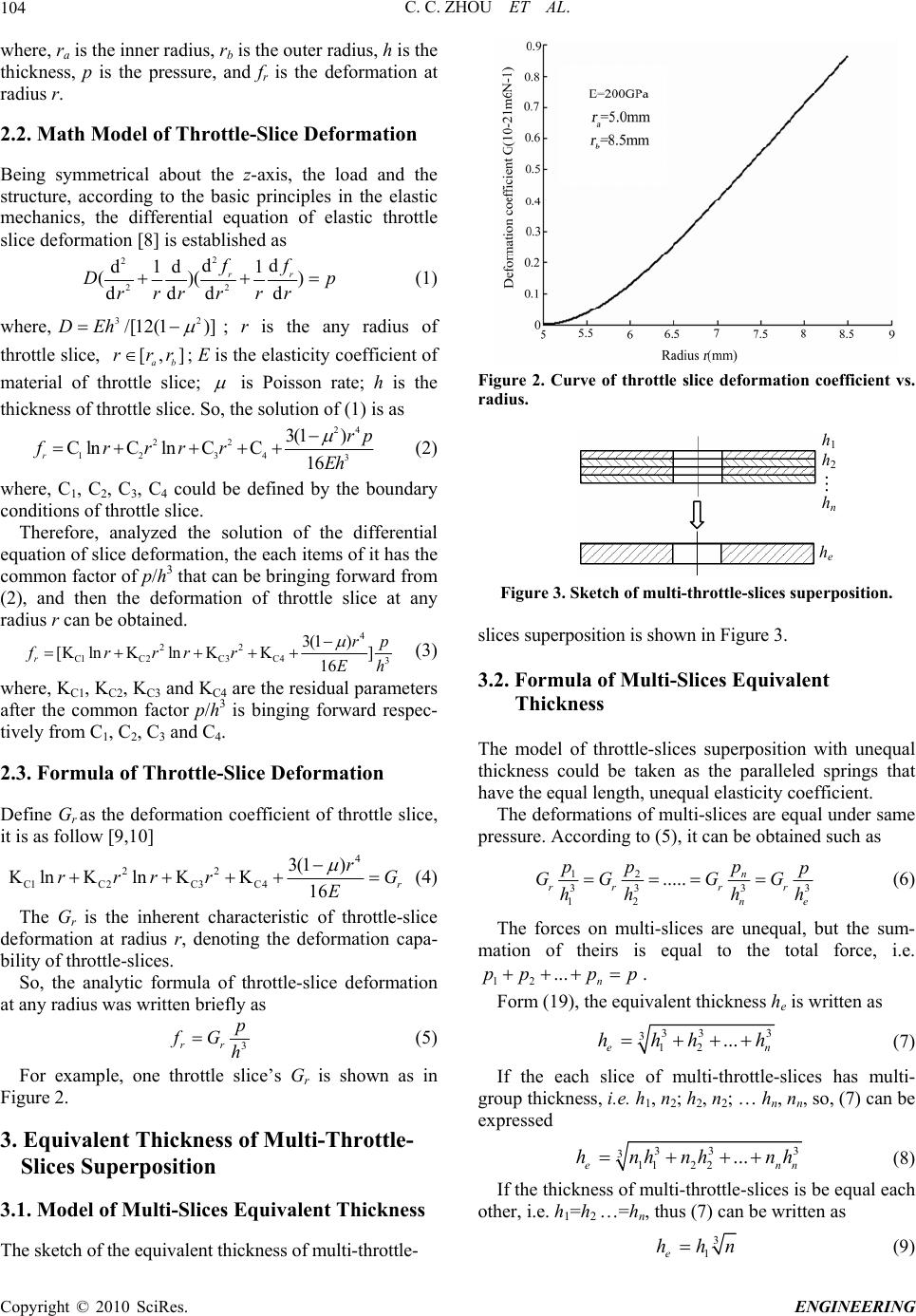 C. C. ZHOU ET AL. Copyright © 2010 SciRes. ENGINEERING 104 where, ra is the inner radius, rb is the outer radius, h is the thickness, p is the pressure, and fr is the deformation at radius r. 2.2. Math Model of Throttle-Slice Deformation Being symmetrical about the z-axis, the load and the structure, according to the basic principles in the elastic mechanics, the differential equation of elastic throttle slice deformation [8] is established as 2 2 22 dd d1d 1 ()( ) ddd d rr ff Dp rrrrrr 2 (1) where, 3 /[12(1 )]DEh [,] ab rrr ; r is the any radius of throttle slice, ; E is the elasticity coefficient of material of throttle slice; is Poisson rate; h is the thickness of throttle slice. So, the solution of (1) is as 24 22 12 343 3(1 ) Cln Cln CC16 r rp frrrrEh (2) where, C1, C2, C3, C4 could be defined by the boundary conditions of throttle slice. Therefore, analyzed the solution of the differential equation of slice deformation, the each items of it has the common factor of p/h3 that can be bringing forward from (2), and then the deformation of throttle slice at any radius r can be obtained. 4 22 C1C2C3 C43 3(1 ) [K lnKlnKK] 16 r rp frrrrEh (3) where, KC1, KC2, KC3 and KC4 are the residual parameters after the common factor p/h3 is binging forward respec- tively from C1, C2, C3 and C4. 2.3. Formula of Throttle-Slice Deformation Define Gr as the deformation coefficient of throttle slice, it is as follow [9,10] 4 22 C1C 2C 3C 4 3(1 ) Kln Kln KK16 r r rrrr E G (4) The Gr is the inherent characteristic of throttle-slice deformation at radius r, denoting the deformation capa- bility of throttle-slices. So, the analytic formula of throttle-slice deformation at any radius was written briefly as 3 rr p fG h (5) For example, one throttle slice’s Gr is shown as in Figure 2. 3. Equivalent Thickness of Multi-Throttle- Slices Superposition 3.1. Model of Multi-Slices Equivalent Thickness The sketch of the equivalent thickness of multi-throttle- Figure 2. Curve of throttle slice deformation coefficient vs. radius. h1 h2 hn he Figure 3. Sketch of multi-throttle-slices superposition. slices superposition is shown in Figure 3. 3.2. Formula of Multi-Slices Equivalent Thickness The model of throttle-slices superposition with unequal thickness could be taken as the paralleled springs that have the equal length, unequal elasticity coefficient. The deformations of multi-slices are equal under same pressure. According to (5), it can be obtained such as 12 33 3 12 ..... n rrr r ne p pp p GGG G hh h 3 h (6) The forces on multi-slices are unequal, but the sum- mation of theirs is equal to the total force, i.e. 12 ... n ppp p . Form (19), the equivalent thickness he is written as 33 3 12 ... e hhh h 3 n (7) If the each slice of multi-throttle-slices has multi- group thickness, i.e. h1, n2; h2, n2; … hn, nn, so, (7) can be expressed 33 3 112 2... en hnhnh nh 3 n (8) If the thickness of multi-throttle-slices is be equal each other, i.e. h1=h2 …=hn, thus (7) can be written as 3 1e hhn (9) 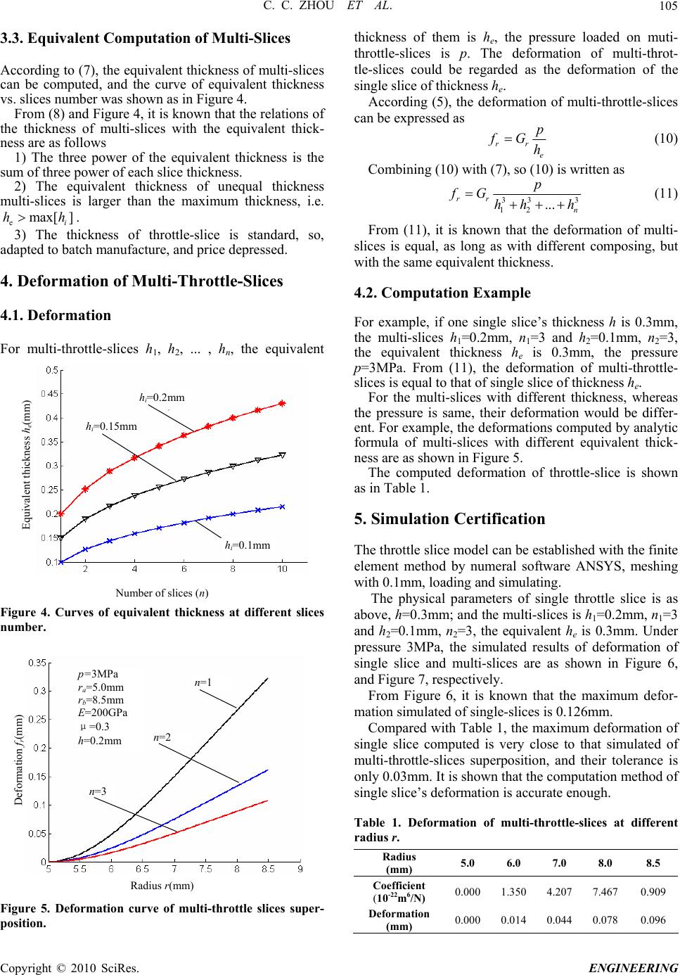 C. C. ZHOU ET AL.105 Radiu (mm) Figure 5. Deformation rottle slices super- position. ices is p. The deformation of multi-throt- 3.3. Equivalent Computation of Multi-Slices According to (7), the equivalent thickness of multi-slices can be computed, and the curve of equivalent thickness vs. slices number was shown as in Figure 4. From (8) and Figure 4, it is known that the relations of the thickness of multi-slices with the equivalent thick- ness are as follows 1) The three power of the equivalent thickness is the sum of three power of each slice thickness. 2) The equivalent thickness of unequal thickness multi-slices is larger than the maximum thickness, i.e. . emax[ ] i hh 3) The thickness of throttle-slice is standard, so, adapted to batch manufacture, and price depressed. 4. Deformation of Multi-Throttle-Slices 4.1. Deformation F or multi-throttle-slices h1, h2, ... , hn, the equivalent Number of slices (n) Figure 4. Curves of equivalent thickness at different slices number. s r curve of multi-th thickness of them is he, the pressure loaded on muti- throttle-sl tle-slices could be regarded as the deformation of the single slice of thickness he. According (5), the deformation of multi-throttle-slices can be expressed as rr p fG h (10) e Combining (10) with (7), so (10) is written as 333 12 ... rr n hh h p fG (11) From (11), it is known that the defor slices is equal, as long as with different composing, but wi ’s thickness h is 0.3mm, 3 and h2=0.1mm, n2=3, blished with the finite are ANSYS, meshing 1 1 mation of multi- th the same equivalent thickness. 4.2. Computation Example For example, if one single slice the multi-slices h1=0.2mm, n1= the equivalent thickness he is 0.3mm, the pressure p=3MPa. From (11), the deformation of multi-throttle- slices is equal to that of single slice of thickness he. For the multi-slices with different thickness, whereas the pressure is same, their deformation would be differ- en Equivalent thickness he(mm) hi=0.2mm hi=0.15m m t. For example, the deformations computed by analytic formula of multi-slices with different equivalent thick- ness are as shown in Figure 5. The computed deformation of throttle-slice is shown as in Table 1. hi=0.1mm 5. Simulation Certification The throttle slice model can be esta element method by numeral softw with 0.1mm, loading and simulating. The physical parameters of single throttle slice is as above, h=0.3mm; and the multi-slices is h=0.2mm, n=3 and h2=0.1mm, n2=3, the equivalent he is 0.3mm. Under pressure 3MPa, the simulated results of deformation of single slice and multi-slices are as shown in Figure 6, and Figure 7, respectively. From Figure 6, it is known that the maximum defor- mation simulated of single-slices is 0.126mm. p=3MPa n=1 ra=5.0mm Compared with Table 1, the maximum deformation of single slice computed is very close to that simulated of multi-throttle-slices superposition, and their tolerance is only 0.03mm. It is shown that the computation method of single slice’s deformation is accurate enough. Table 1. Deformation of multi-throttle-slices at different adius r. r Radius (mm) 5.0 6.0 7.0 8.0 8.5 Coefficien 0-22m6/N t (1) 0.000 1.350 4.207 7.4670.909 Def (mm) 0.000 0.014 0.044 0.0780.096 ormation rb=8.5mm E=200GPa μ=0.3 h=0.2mm Deformation fr(mm) n=2 n=3 Copyright © 2010 SciRes. ENGINEERING  C. C. ZHOU ET AL. Copyright © 2010 SciRes. ENGINEERING 106 Figure 6. Deformation map simulated of single-throttle slices. Figure 7. Deformation map simulated of multi-throttle-slices superposed. nalytic computation and simulation certificatio ickness of multi-throttle-slices, it is lytic formula of equivalent thickness With it, the equivalent thickness of multi-throttle-slices with different thickness can computed accurately. The deformation comput of multi-slices is close to e- sli re Science Foundation of ) for the funding support. ] D. F. Yu and Q. H. Chen, “Design study of smooth- nsion shock absorber outer characteristic,” Acta Armamentarll: The Volume of Tank, for small electric vehicles,” Journal of Asian Elec- ce and c Vehicles, ian Electric Vehicles, . 10–16, 2001. . 19–21, u, L. Gu, and L. Wang, “Bending deformation and l. 26, No. 7, pp. 581–584, 2006. . 43, No. be ed that simulated by ANSYS. It is shown that the computa- tion method of the equivalent thickness of multi-throttl ces is accurate enough, can be used to design the pa- rameters of throttle-slices of shock absorber. 7. Acknowledgment The authors thank the Natu Shandong (No. Y2007F72 8. References [1 ness-to-safety ratio in suspe Armored Vehicle and Engine, Vol. 87, No. 3, pp. 11–17, 2002. [2] C. C. Zhou, Z. Y. Zheng, and X. Y. Zhang, “Design method for throttle holes area of telescopic shock ab- sorber tric Vehicles, Vol. 7, No. 1, pp. 1191–1197, 2009. [3] X. M. Fen and Z. M. Liu, “Development and current situation of automobile hydraulic telescopic damper technology,” Journal of Wuhan University of Scien Technology, Vol. No. 8, pp. 340–343, 2003. [4] T. Ashida, D. Tanaka and S. Minami, “A method to de- termine the velocity profiles from the power consumption of electric vehicles,” Journal of Asian Electri Vol. 5, No. 2, pp. 1027–1032, 2007. [5] S. Matsugaura, H. Nishimura, M. Omae, et al, “Devel- opment of a driver-monitoring vehicle based on an ultra small electric vehicle,” Journal of As Vol. 3, No. 2, pp. 758–762, 2005. [6] S. M. Li, Z. H. Lü, “Technology development of cylindri- cal fluid drag shock absorber for motor vehicle,” Automo- bile Technology, Vol. 32, No. 8, pp From Figure 7, it is known that the maximum defor mation simulated of multi-throttle-slices is 0.101mm - respectively. Compared with Table 1, the maximum deformation computed of multi-throttle-slices superposition is close to that simulated, the tolerance is only 0.005mm. It is sh [7] Y. Chen, H. E. Hui and J. F. Bai, “Analysis of hydraulic shock absorber spring valve chip deformation of charade car,” Automobile Technology, Vol. 31, No. 1, pp 2000. [8] Z. L. Xu, “Elasticity mechanics,” Beijing: Higher Educa- tion Press, 2001. [9] C. C. Zho own that the computation method of the equivalent thickness of multi-throttle slices superposition is accurate enough. 6. Conclusions y the a coefficient of throttle-slice,” Transactions of Beijing Institute of Technology, Vo Bn [1 to the equivalent th nown that the anak 6, pp 0] C. C. Zhou and L. Gu, “Superposition throttle slices opening size and characteristic test of telescopic damper,” Chinese Journal of Mechanical Engineering, Vol . 210–215, 2007. of multi-throttle slices is accurate, simple and applied. |