Paper Menu >>
Journal Menu >>
 Wireless Sensor Network, 2010, 2, 186-196 doi:10.4236/wsn.2010.22024 y 2010 (http://www.SciRP.org/journal/wsn/). Copyright © 2010 SciRes. WSN Published Online Februar Achieving Directionality and Transmit Diversity via Integrating Beam Pattern Scanning (BPS) Antenna Arrays and OFDM Peh Keong Teh, Seyed Alireza Zekavat Department of Electrical and Computer Engineering, Michigan Technological University, Houghton, USA E-mail: {pteh, rezaz}@mtu.edu Received July 28, 2009; revised October 25, 2009; accepted November 19, 2009 Abstract In this paper, we introduce a novel merger of antenna arrays with scanning beam patterns, and Orthogonal Frequency Division Multiplexing (OFDM) systems. Controlled time varying phase shifts are applied to the antenna array elements mounted at the base station with beam patterns directed toward the desired user. This creates a small beam pattern movement called Beam Pattern Scanning (BPS). In rich scattering environments BPS creates a time varying environment leading to time diversity exploitable at the receiver enhances its probability-of-error performance. Here, we apply OFDM signals to BPS antenna arrays, and we achieve: (1) directionality, which supports Space Division Multiple Access (SDMA); and (2) a time diversity gain, which leads to high performance. We discuss the structure of the base station antenna array and the OFDM receiver that exploits time diversity. We also introduce the merger of BPS and multi-carrier OFDM (MC-OFDM) systems. In MC-OFDM each bit is transmitted over all sub-carriers after serial to parallel conversion. BPS/ MC-OFDM receiver exploits both time diversity inherent in BPS, and frequency diversity inherent in MC-OFDM transmission technique. Simulation results show high Probability-of-error performance is achie- vable via BPS/OFDM and BPS/MC-OFDM schemes comparing to the traditional OFDM and MC-OFDM, respectively. Simulations also reveal that MC-OFDM system as well as its merger with BPS is capable of mitigating large Peak-to-Average Ratio (PAPR) problem in traditional OFDM system. In addition, perform- ance simulations with coded OFDM (COFDM) and coded MC-OFDM (MC-COFDM) and their merger with BPS are studied. Keywords: OFDM, MC-OFDM, Antenna Array, Beam Pattern Scanning, Transmit Diversity. 1. Introduction OFDM (Orthogonal Frequency Division Multiplexing) is an emerging technique capable of high data rate trans- mission over frequency selective channels without im- plementation of complex equalizers [1–5]. Due to its inherent benefits, OFDM has been proposed as the basic modulation technique for the 4th generation wireless systems. In an N sub-carriers OFDM system, a block of N information bits are serial to parallel converted and modulated via N orthogonal sub-carriers (each bit over one sub-carrier). They are then summed and transmitted simultaneously [1–5]. This process extends the symbol duration from Ts to NTs. MC-OFDM (Multi-Carrier OFDM) is an innovative OFDM transmission technique where each MC-OFDM user’s bit is transmitted over all available sub-carriers simultaneously [6–8]. To ensure separability of the bits at the receiver and reduce inter-bit-interference (IBI), orthogonal codes, e.g., Hadamard Walsh codes, are ap- plied to the sub-carriers of each bit. Through MC-OFDM, frequency diversity can be exploited to improve the per- formance of the system with minimal complexity in the transmitter and receiver [7,8]. Properly designed OFDM and MC-OFDM systems convert the channel to a flat fading channel and eliminate the need for complex equalizers. This is achieved via sel- ecting N such that NTs becomes much larger than chan- nel delay spread. However, there is a drawback associ- ated with flat fading: If sub-carriers experience deep fade, the bit will be rendered unrecoverable and thereby de- grades the system probability-of-error performance. This issue can be resolved via diversity techniques. In MC- OFDM signals are transmitted over all sub-carriers,  P. K. TEH ET AL.187 which allow frequency diversity to be exploited at the receiver [6–8]. Besides frequency diversity, various me- thods such as: 1) Forward Error Correction Coding at the cost of the overall system throughput [1,2], and 2) trans- mit diversity has been used to improve the probability- of-error performance of OFDM and MC-OFDM systems [9,10]. In this work, we merge OFDM systems with a transmit diversity scheme created via beam pattern movement (scanning). The concept of beam pattern movement has been ref- erenced in the literature, some with a different approach, and some with no further exploration. For example, in [11], researchers introduce “jitter diversity”. In that work, with a high angular spread at the mobile receiver, the beam pattern is jittered around its usual position to create angle diversity and enhance the receiver performance; and it does not lead to time diversity. In [12], there is a very short (just one line) reference to the idea of antenna pattern movement to create time diversity. The authors state that one can force the antenna to oscillate when the vehicle is traveling at low speeds, channel’s fade is slow, and time diversity cannot be exploited. Recently, a powerful transmit diversity technique has been introduced called beam pattern scanning (BPS) (also known as beam pattern oscillation). In this scheme, antenna arrays are installed at the base station (BS) with their scanning (oscillating) antenna patterns directed to- ward the desired users [13,15]. A time varying phase shift is applied to each antenna element in order to steer and move the antenna pattern within one symbol dura- tion Ts (or within NTs in OFDM systems). The beam pat- tern starts sweeping an area of space at time zero, it re- turns to its initial position after time Ts (NTs in OFDM) and repeats its sweeping. The movement of the beam pattern is small, e.g., in the order of 5% of half power beam width (HPBW). Hence, the desired user stays in the antenna array HPBW at all times. In rich scattering environments, as a result of the de- parture and arrival of scatterers within the window of antenna beam pattern, BPS creates a time varying chan- nel with a small controlled coherence time Tc with re- spect to Ts (NTs) [8,13,14]. This leads to a fast fading channel via which time diversity benefits can be ex- ploited at the receiver [16]. Therefore, BPS is introduced as a transmit diversity scheme that enhances: a) receiver probability-of-error performance via time diversity, and b) wireless network capacity via Spatial Division Multi- ple Access (SDMA) [17] or spatial filtering interference reduction (SFIR) [18]. In this paper, we merge BPS transmit diversity with OFDM and MC-OFDM systems. This merger achieves: 1) high probability-of-error performance by time diver- sity induced at the receiver via BPS [8,15,19], and 2) high capacity via directionality created via antenna ar- rays mounted at the transmitter [17–20], with a 3) low complexity due to the structure of OFDM and BPS. The structure of BPS is simple because the complexity is mainly focused at the base station antenna array. In this work, we present and discuss: a) the antenna ar- ray structure that makes BPS possible for OFDM systems incorporating a number of sub-carriers, b) the OFDM receiver structure capable of exploiting the time diversity induced by BPS, and c) the MC-OFDM receiver capable of exploiting time diversity via BPS and frequency diver- sity through Multi-carrier scheme. We simulate the prob- ability-of-error performance and the peak-to-average ratio (PAPR) curves for both BPS/OFDM and BPS/MC- OFDM. Traditional OFDM and MC-OFDM utilizing antenna arrays without BPS scheme are used as benchmark agai- nst BPS/OFDM and BPS/MC-OFDM schemes. Adaptive antenna arrays with beam patterns directed towards in- tended users leads to capacity enhancement via SDMA [20–22] without enhancing the performance. This paper highlights performance benefits achieved through BPS and OFDM systems (OFDM and MC-OFDM) merger. In addition, coded version of OFDM systems and BPS merged systems (BPS/COFDM and BPS/MC-COFDM) are simulated and compared to further underline the per- formance improvement through BPS merger. Section 2 introduces OFDM and MC-OFDM systems, BPS technique and the antenna array structure. In Sec- tion 3, we present BPS/OFDM and BPS/MC-OFDM received signal and their receiver structure. In Section 4, we present the probability-of-error performance and peak-to-average ratio simulations. Section 5 concludes the paper. 2. OFDM, MC-OFDM, Antenna Array Structure and BPS Techniques 1) OFDM system: In OFDM, a block of N bits are trans- mitted simultaneously over N sub-carriers (each bit over one sub-carrier) after serial to parallel conversion, which converts the duration of transmitted symbols from Ts to NTs (see Figure 1). The number of sub-carriers N is cho- sen to ensure flat fading channel at all times (i.e., channel delay spread Tm << NTs), and the sub-carriers are sepa- rated by s NT f1 (1) to ensure the orthogonality of sub-carriers and avoid in- ter-carrier interference at the receiver. The OFDM transmitted signal corresponds to: )(][Re)( 1 0 )(2 sNT N n tfnfj iiNTtgeiNnbts s o (2) where b[·]{+1,-1} is the transmitted bit, i {0,1,2,…} is the ith group of N bits simultaneously converted to par- Copyright © 2010 SciRes. WSN  P. K. TEH ET AL. 188 NTs allel (n represents the bit number), fo is the carrier fre- quency and is a rectangular waveform of unity height over zero to NTs (Ts refers to symbol duration). )(tg s NT 2) The MC-OFDM system: In MC-OFDM system, all N bits are transmitted simultaneously over all N sub- carriers. To maintain orthogonality across bits, an or- thogonal code, e.g., Hadamard Walsh code, is assignedto the sub-carrier of each bit (see Figure 2). By transmitting all N bits simultaneously, the symbol duration is con- verted from Ts to NTs. Hence, the MC-OFDM transmitted signal corresponds to: )(][Re)( 1 0 1 0 )(2 sNT N k N n tfnfj n ki iNTtgeiNkbts s o (3) where is the kth bit and n th sub-carrier orthogonal codes’ element. Other parameters have been defined in (2). n k 3) Proposed Antenna Array Structure: We assume an M-element linear antenna array mounted at the Base Sta- tion (B.S.) (Figure 3). In order to move the antenna pat- tern, a time varying phase, m (t), is applied to the mth antenna array element (Figure 3). Moreover, in Figure 3 the angle o represents the direction of the antenna beam pattern (angle-of-arrival of the signal) with respect to the antenna array main axis. Here, for simplicity in presenta- tion, it is assumed that the desired mobile is located at angle o = 0 (i.e., antenna array main axis and beam pat- tern main axis are overlapped). In this case, the normal- ized array factor characterizing the resulting antenna pattern corresponds to: ),(sin ),(sin 1 ),( 2 1 2 t t M tAF M , (4) where )(sin 2 ),(tdt o . (5) 1 N k 1 k 0 k Nj e )1(2 f j e)1(2 f j e)0(2 ][kb … (b) Figure 2. (a) MC-OFDM transmitter structure; (b) kth bit transmitter design. (a) )(tsi Bit 1 tran s - Bit 2 tran s - Bit K tran s - ][kb ]2[b … ]1[b Information bits Figure 1. OFDM transmitter structure. Serial to Parallel ]1[ Nb ]0[b ]1[b ftj e02 ftNj e)1(2 tfj o e 2 Informa- tion bits b[0] si(t) . . . b[N-1] ftj e12 NTs C opyright © 2010 SciRes. WSN  P. K. TEH ET AL.189 Here, o is the wavelength (c/fo), d is the distance be- tween antenna elements, and (2 d/ o) sin represents the phase offset due to the difference in distance between antenna array elements and the mobile. In general, antenna array half power beam width (HPBW) changes with frequency (sub-carrier). For nar- rowband OFDM systems, the variation in HPBW is neg- ligible (see Figure 4); however, for wideband and high data rate OFDM systems, e.g., 60 Mb/s data rate, the variation of beam pattern with sub-carriers is consider- able (see Figure 4). In order to achieve directionality via sectoring strategy (e.g., in switched beam smart antenna systems), identical beam patterns are required for all N sub-carriers. Since different sub-carriers create different HPBWs, users located near the border of two sectors may experience either: 1) large interference from the beam pattern of unintended sector, or 2) a reduction in power in the desired signal in the beam pattern from the desired sector [15]. We must then ensure that the size of sub-carriers ap- plied to antenna array is small enough that all the sub-carriers placed in the antenna array generate identi- cal patterns. Hence, we introduce the following defini- tion: Definition 1: Beam Patterns are considered identical if the variation in null-to-null beam width (B.W. in Figure 4) of the beam patterns created via sub-carriers are within 10% of the average null-to-null beam width (B.W.)ave. Based on this definition, it can be shown via simulations that whenever the minimum frequency, fmin, and the maximum frequency, fmax, applied to an antenna array satisfy 01.0 .min.max o f ff , (6) “identical” beam patterns are observed (see [15]). Con- sidering a contiguous bandwidth for OFDM systems, this criterion corresponds to 01.0 o f f N (7) If (6) is not satisfied, the N sub-carriers of the OFDM system should be divided into P groups of Q ≤ N (N = PQ) neighboring sub-carriers such that Q fo/f ≤ 0.01. Then, either each set of Q sub-carriers should be applied into a (a) (b) Figure 4. 32 sub-carriers OFDM system, center frequency 4.0GHz. (a) Narrow band system with band- width of 200MHz; (b) Wide band system with bandwidth of 2GHz. Figure 3. Antenna structure. OFDM or MC-OFDM transmitter (Figures 1 & 2) Information bits ])([02 o tj ])([12 o tj e e ])()[1(2 o tMj e Beam Pattern Element #0 1Element # Element #M-1 d o Main axis Di- rection Antenna Array Main axis Di- rection y x Copyright © 2010 SciRes. WSN  P. K. TEH ET AL. 190 unique M-element antenna array or unique complex should be applied to antenna elements for each set weights of sub-carriers [15,17,19]. In this work, we assume a nar- row band system with Q = N, P = 1, i.e., all of sub-carri- ers, fn = fo + n f, n {0,1,…,N-1} are applied to one an- tenna array (see Figure 3). 4) Beam Pattern Scanning Technique: The scanning of beam pattern is created at the B.S. by applying time varying phase offsets m (t) to the antenna array element m{1,2, …,M} (Figure 3). The antenna array’s beam pattern movement should ensure: 1) constant large scale fading, and 2) L independent fades to be generated within each NTs. This creates an L-fold diversity gain at the mo- bile receiver. After each NTs, (t) returns the beam pat- tern to its t = 0 position and repeats an identical spatial sweeping movement over the next NTs period (Figure 5(a)). In order to ensure constant large-scale fading, the mo- bile must remain within the antenna array’s HPBW over each symbol duration NTs. This condition corresponds to [22]. 10, dB dt NTs where B is the HPBW, is the azimuth (8) angle (direction of arrival), d /dt is the rate of antenna pattern movement, and NTs·(d /dt) is the amount of antenna pattern move- ment within NTs. The parameter , 0 < < 1, is the con- trol parameter ensures the received antenna pattern am- plitude is within the HPBW for the entire symbol dura- tion. The phase offset applied to the antenna array is calculated using (8) leads to [9] (see Figure 5(b)): cos2 )( s NT t Bd t 2 so NT (9) Specifically, to solve for (9) from (8) (detail we p of scat- ed in [20]), roceed as follows: 1) Using (5), we solve for at a fixed value of (t, ) = o; 2) substituting this value into (8) and differentiating, we create a differential equation for (t); and (3) finally, we solve the differential equation which leads directly to (9). Sweeping of the antenna pattern creates a time-varying channel with a coherence time that is a function tering environment and may lead to L independent fades over NT s. Geometric-based stochastic channel modeling scheme is used to evaluate the channel diversity gain [11]. Channel coherence time calculated in [15] assum- ing a medium size city center (e.g., 3 scatterers per 1000m2), with 0.0005 < < 0.05 shows that diversity gain as high as L 7 is achievable via BPS scheme. The main assumption in this modeling scheme is: 1) A semi-elliptical coverage with the mobile at its center (suitable when we assume the height of the BS er Design plicity in presentation, we con- i = 0 (10) Applying this signal to the antenna array in the outh (11 The total normalized downlink sid 0 MS BS antenna array is close to the height of surrounding build- ings); 2) The movement generated by antenna array oscilla- tion is dominant, and hence the movement of mobile and other relative speed object in the environment is ignored; 3) Scatters are assumed to have dimensions in accor- dance with a known PDF [13]; 4) Scatters in the surrounding BS are uniformly dis- tributed; 5) Scatters are consider diffused reflectors which re- flect the incident radiation in all direction; and, 6) The signal received at the mobile is sum of hori- zontally propagated plane waves interacting with just one scatterer. 3. Receiv 1) BPS/OFDM: For sim sider in (2). We represent the OFDM transmitted signal as: )( 1 0 N ts ],0[,)(2cos][ 0 s n oNTttfnfnb Figure 3 tput of the m element of the antenna array is ,0[,)()(cos][)( 1N NTttmtfnfnbts ]2 0 s n om ) transmitted signal, con- ll m) is: ering all antenna elements (a (t) NTs o d cos2 S NT t Figure 5. (a) Beam pattern scanning; (b) Antenna element delay line function. (b) (a) C opyright © 2010 SciRes. WSN  P. K. TEH ET AL. 191 ],0[)()(2cos 1 ][)( 1 0 1 0 s M m o N n NTttmtfnf M nbts (12) Since the range of the control parameter ien 0 < < 0.05 in the frequency offset induced by (t) in the transmitted signal is less than 5% and can be ignd. Typically, as it is seen in (9), assuming half wavelength spacing across antenna elements, a = 128, and B / 6 (for 4 element antenna), and T = 10-6, the maximum frequency drift would be in minimal compared to the typical carrier frequency of 2.4 GHz. At the receiver side, considering the transmit diver- sity leads to L-fold time diversity, the received signal [0,NTs] can be divided into time slot l s tak (8), ore nd N s the order of 100 Hz, which is s [lNTs/L, (l+1)NTs/L], {0,1,…,L-1}, and these time slots demonstrate inde- pendent fades. The received signal can then be repre- sented as 1 0 1 0 )(2cos 1 ][ 1 )( M m o N n n ll tfnf M nb L tr ]/)1(,/[)(),( LNTlLlNTttntmssl n l (13) where, nl(t) is an additive white Gaussian noise (AWGN), which is independent for different time slots (l), n l is the Rayleigh fade amplitude on nth sub-carrier in the lth time slots, and n l is the fading phase offset in the nth sub-carrier th and me slot (hereafter, this pha is assumed to be tacked and removed). The Raylei amplitudes are dered independent over tim related over suers. The correlation coeffici tween carrier is characterized by [23] l ti r consi b-carri ' and se offset gh fade ent be- e and cor- n''n 2 '',' ))/(()'''(1 1 c nn ffnn p (14) where (∆f) is the coherence bandwidth of the channel. Moreover, c ),( t in (13) is introduced in (5). Applying the summation over m, (13) corresponds to cos),(][)( 1 0 tAFnbtr N n n ll )(),( 2 1 )(2 t M tfnfo tnn l (15) Here, AF(t, ) introduced in (4), is the n tenna array factor. Assuming a narrow-be ak d na array pat- tern over NTs, the array factor experience over [0,NTs] is well approximated by AF(t, ) 1. The BPS/OFDM receiver is shown in Figure 6. In this figure, “Re” refers to Real Part, and “Im” refer Imaginary Part. In addition, after the application ormalized an- am width an- tenna array and the mobile is located at o = 0, (5) can be approximated by (t, ) = (t) = (t). Assuming that an- tenna array peirected towards the intended mobile at time 0, and with small movements of anten s to of )( 2 1 2 2 1t M tfj s o e NT v (16) and returning the OFDM to baseband, a bank of band- pass filters are used to separate the OFDM signal into its N multiple sub-carriers: The baseband signal is inte- grated over each interval of t [lNTs/L, (l+1)NTs/L], l {0,1,…,L-1} in order to exploit time diversity components cr Figure 6. BPS-OFDM receiver. eated by beam pattern scanning [14,15]. The received signal for each subcarrier, n and l time slot corresponds to )(trlRe{·} to Im{ · } v Band Pass Filter Band Pass Filter ftj 02 e0 l r Band Pass Filter ftj e 12 ftNj e )1(2 . . . . . LNTl lNT s dt /)1( L s/ l { 0,1,…,L - 1 } l { 0,1,…,L - 1 } l {0,1,…,L-1} . . . . . LNT L s s dt / / l lNT )1( LNTl L lNT s dt /)1( / 1 l r 1N l r Combining over time components Decision Device b ˆ Parallel to Serial C opyright © 2010 SciRes. WSN  P. K. TEH ET AL. 192 nnnb NT L rn l n l s n l,][ 2 1 ,...,1,0{},1,...,1,0{ LlN }1 (17) where is a zero-mean Gaussian random variables with variance No/2. The first term in (17) represents lth nth component of the desired signal and the second term is noise. With N L diversity com, N over fre- quency a over time, the combiner can be design to utilize dit combining techniques such as Equal Gain Coming (EGC) or Maximumo Combining (MRC) (in single user environmentum Mean Square Error Combining (MMSEC) leads to a similar result as MRC). 2) BPS/MC-OFDM: Here, we co= 0 in (3) and we ignore pulse shaping function n l n ponents nd L fferen bin Rati , Minim nsider i )( t g s NT . The MC-OF- DM transmitted signal corresponds to ,)(2cos][)( 1 0 1 0 0 N k N n o n ktfnfkbts t],0[ s NT (18) This signal is applied to the antenna array in Figure 3 and the output of the mth element of the atenna array is given by, n ,)()(2cos][( o n km tmtfnfkbs ) 1 1 N N t 0 0k n }1,...,1,0{],,0[ MmNTt s (19) Considering all antenna elements (all m), the total normalized downlink transmitted signal is 1 0 1 0 1 0 )()(2cos 1 ][)( N k M m o n k N n tmtfnf M nbts ],0[ s NTt (20) Again, in (20) the frequency offset induced by (t) in the transmitted signal is minimal a ignored, since the range of the control parameter < nd it is 0.05 in (6) creates less than 5% bandwidth expansion. At the receiver, since the transmit diversity leads to an L-fold time diversity, the received signal can be divided into time slots [lNTs/L, (l+1)NTs/L], l {0,1,…,L-1} and each individua de l slot monstrates independent fades. The received signal can be represented as 1N 1 00 1 0 )(2cos 1 ][)( M m o k N n n k n ll tfnf M nbtr ]/)1(,/[)(),( LNTlLlNTttntm ssl n l w l the nth sub-carrier in the lth time slots, and l n is the fading phase offset in the nth sub-carrier in the lth time slot (hereafter, this phase offset is assumedo be tracked and removed). The Rayleigh fade amplitudes, l n, are independent over time (l) and correlated over sub-carriers (n) with the cor- relation coefficient between sub-carriers and rized b4). Applying the summation over m, (21) correspond (21) here, nl(t) is an additive white Gaussian noise (AWGN), which is considered independent for different time slots (l), n is the Rayleigh fade amplitude on t 'n''n charactey (1 s to n lb (2cos 1 0 1 0 )),(][)( N k o n k N n ltfnftntr AF )(),t of ( 2 1tn M l (22) structure BPS/MC-OFDM receiver is shown in Figure 7 (Fure 7(b) represents jth bit receiver). The received signal for each sub-carrier, n and time slot l can be represented by The ig 1 0 ][ 2 1 ][ 2 1 ][ N jk k n j n k n l s n l s n lkb NT L jb NT L jr }1,...,1,0{},1,...,1,0{, LlNnnn l (23) where nl n is a zero-mean Gaussian random variables with variance No/2. In (23), the first term represent the desired signal, the seco ce and the t is 2) Maximum Ratio Combining (MRC) (2) 3) Minimum Mean Square Error Combining (MMSEC) nd term represents the inter-bit-interferen- hird term represents the noise. The factor 1/L the direct consequence of dividing the received signal into L partitions creating L-fold time diversity. The com- biner can be designed to utilize different combining techniques in frequency and time domain. Different combining methods in frequency domain are: 1) Equal Gain Combining (EGC) 1 0 , N n n lEGClrR , (24) 1 0 , N n n l n lMRCl rR , 5 1 00 2 , 2 )( N nn l n l n lMMSECl N N rR (26) Here, we present only Equal Gain Combining (EGC) in the time domain to exploit the diversity induced by BPS. 4. Simulated Performance Simulations are provided for MC-OFDM systems with antenna arrays. The assumptions for these simulations are as follow: 1) N = 32 sub-carriers in the MC-OFDM system; 2) L = 7 independent fades are achievable as a result of the beam-pattern movement in the duration NTs C opyright © 2010 SciRes. WSN 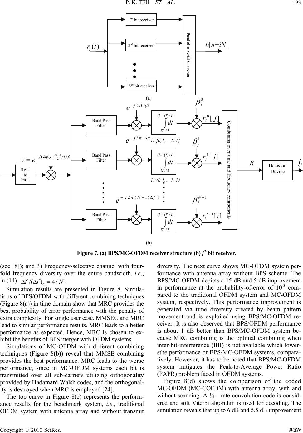 P. K. TEH ET AL. 193 (see [8]); and 3) Frequency-selective channel with four- fold frequency diversity over the entire bandwidth, i.e., in (14) Simulation results are presented in Figure 8. Simula- tions of BPS/OFDM with different combining techniques (Figure 8(a)) in time domain show that MRC provides the best probability of error performance with the penalty of extra complexity. For single user case, MMSEC and MRC lead to similar performance results. MRC leads to a better performance as expected. Hence, MRC is chosen to ex- hibit the benefits of BPS merger with OFDM systems. Simulations of MC-OFDM with different combining techniques (Figure 8(b)) reveal that MMSE combining provides the best performance. MRC leads to the worse performance, since in MC-OFDM systems each bit is transmitted over all sub-carriers utilizing orthogonality provided by Hadamard Walsh codes, and the orthogonal- ity is destroyed when MRC is employed [24]. The top curve in Figure 8(c) represents the perform- ance results for the benchmark system, i.e., traditional OFDM system with antenna array and without transmit diversity. The next curve shows MC-OFDM system per- formance with antenna array without BPS scheme. The BPS/MC-OFDM depicts a 15 dB and 5 dB improvement in performance at the probability-of-error of 10-3 com- pared to the traditional OFDM system and MC-OFDM system, respectively. This performance improvement is generated via time diversity created by beam pattern movement and is exploited using BPS/MC-OFDM re- ceiver. It is also observed that BPS/OFDM performance is about 1 dB better than BPS/MC-OFDM system be- cause MRC combining is the optimal combining when inter-bit-interference (IBI) is not available which lower- sthe performance of BPS/MC-OFDM systems, compara- tively. However, it has to be noted that BPS/MC-OFDM system mitigates the Peak-to-Average Power Ratio (PAPR) problem faced in OFDM systems. Figure 8(d) shows the comparison of the coded MC-OFDM (MC-COFDM) with antenna array, with and without scanning. A ½ - rate convolution code is consid- ered and soft Viterbi algorithm is used for decoding. The simulation reveals that up to 6 dB and 5.5 dB improvement Figure 7. (a) BPS/MC-OFDM receiver structure (b) jth bit receiver. (b) Nffc/4)/( . (a) 2nd bit receiver Parallel to Serial Crteronve st 1 bit receiver )(trlb[n+iN] ... Nth bit receiver l { 0 , 1 , … , L-1 } Combinin g over time and fre q uenc y com p onents Decision Device b ˆ R Re{} to Im {} ) ) (2(2 1 0ttfj M ev . . . . . Band Pass Filter l { 0 , 1 , … , L-1 } . . . . . LTl L l T s s dt /)1( / ][ 1jrl j 1 ftj e12 Band Pass Filter LTl L l T s s dt /)1( / ftj e 02 l 0 ][ 0jr j Band Pass Filter tfNj e )1(2 LTl L l T s s dt /)1( / ][ 1jr N l 1N j C opyright © 2010 SciRes. WSN 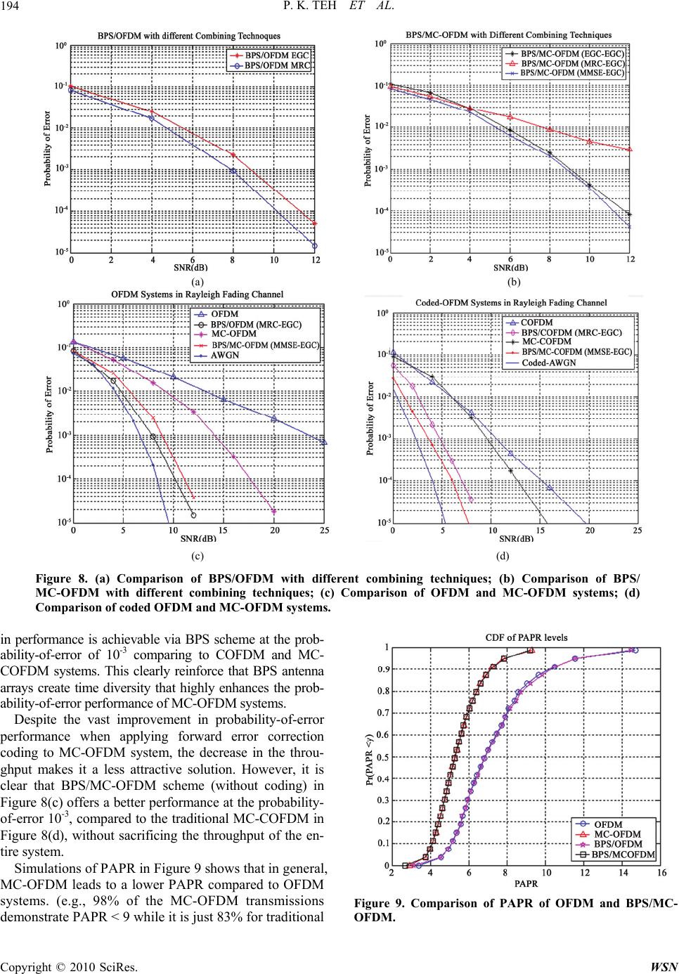 P. K. TEH ET AL. 194 (a) (b) (c) (d) Figure 8. (a) Comparisison of BPS/ C ab on of BPS/OFDM with different combining techniques; (b) Compar MC-OFDM with different combining techniques; (c) Comparison of coded OFDM and MC-OFDM systems. in perforble via omparison of OFDM and MC-OFDM systems; (d) C-OFDM leads to a lower PAPR compared to OFDM systems. (e.g., 98% of the MC-OFDM transmissions demonstrate PAPR < 9 while it is just 83% for traditional mance is achievaBPS scheme at the prob- ility-of-error of 10-3 comparing to COFDM and MC- COFDM systems. This clearly reinforce that BPS antenna arrays create time diversity that highly enhances the prob- ability-of-error performance of MC-OFDM systems. Despite the vast improvement in probability-of-error performance when applying forward error correction coding to MC-OFDM system, the decrease in the throu- ghput makes it a less attractive solution. However, it is clear that BPS/MC-OFDM scheme (without coding) in Figure 8(c) offers a better performance at the probability- of-error 10-3, compared to the traditional MC-COFDM in Figure 8(d), without sacrificing the throughput of the en- tire system. Simulations of PAPR in Figure 9 shows that in general, M Figure 9. Comparison of PAPR of OFDM and BPS/MC- OFDM. C opyright © 2010 SciRes. WSN 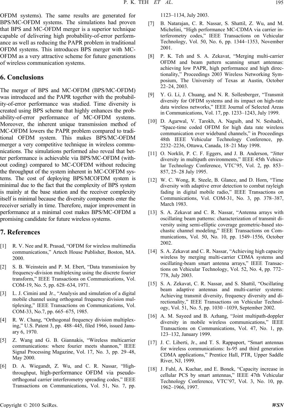 P. K. TEH ET AL.195 OFDM systems). The same results are generated for BPS/MC-OFDM systems. The simulations had proven that BPS and MC-OFDM merger is a superior technique capable of delivering high probability-of-error perform- ance as well as reducing the PAPR problem in traditional OFDM systems. This introduces BPS merger with MC- OFDM as a very attractive scheme for future generations of wireless communication systems. 6. Conclusions The merger of BPS and MC-OFDM (BPS/MC-OFDM) was introduced and the PAPR together with the probabil- ity-of-error performance was studied. Time diversity is created using BPS scheme that highly enhances the prob ability-of-error performance of Moreover, the inherent unique transmission method of MC-OFDM lowers the PAPR problem compared to tradi- tional OFDM system. This makes BPS/MC-OFDM merger a very competitive technique in wireless commu- nications. The simulations performed also reveal that bet- ter performance is achievable via BPS/MC-OFDM (with- out coding) compared to MC-COFDM without reducing the throughput of the system inherent in MC-COFDM sys- tems. The cost of deploying BPS/MCOFDM system is minimal due to the fact that the complexity of BPS system is mainly at the base station and the receiver complexity itself is minimal because the diversity components enter the receiver serially in time. Therefore, major improvement in performance at a minimal cost makes BPS/MC-OFDM a promising candidate for future wireless systems. 7. References [1] R c 2 . 1123–1134, July 2003. [7] B. Natarajan, C. R. Nassar, S. Shattil, Z. Wu, and M. Michelini, “High performance MC-CDMA via carrier in- terferometry codes,” IEEE Transactions on Vehicular Technology, Vol. 50, No. 6, pp. 1344–1353, November 2001. [8] P. K. Teh and S. A. Zekavat, “Merging multi-carrier OFDM and beam pattern scanning smart antennas: achieving low PAPR, high performance and high direc- tionality,” Proceedings 2003 Wireless Networking Sym- posium, The University of Texas at Austin, October 22–24, 2003. [9] Y. G. Li, J. Chuang, and N. R. Sollenberger, “Transmit diversity for OFDM systems and its impact on high-rate data wireless networks,” IEEE Journal of Selected Areas in Communications, Vol. 17, pp. 1233–1243, July . Naguib, and N. Seshadri, “Space-time coded OFDM for high data rate wireless communication over wideband channels,” in Proceedings 48th IEEE Vehicular Technology Conference, pp. 2232–2236, Ottawa, Canada, 18–21 May 1998. [11] O. Norklit, P. C. F. Eggers, and J. B. Anderson, “Jitter diversity in multipath environments,” IEEE 45th Vehicu- lar Technology Conference, VTC’95, Vol. 2, pp. 853– 857, 25–28 July 1995. [12] W. C. Wong, R. Steele, B. Glance, and D. Horn, “Time diversity with adaptive error detection to combat rayleigh fading in digital mobile radio,” IEEE Transactions on Communications, Vol. COM-31, No. 3, pp. 378–387, March 1983. [13] S. A. Zekavat and C. R. Nassar, “Antenna arrays with oscillating beam patterns: characterization of transmit di- versity using semi-elliptic coverage geometric-ba IEEE Transactions on Com- , pp. 1549–1556, October acity wireless by merging multi-carrier CDMA systems and oscillating-beam smart antenna arrays,” IEEE Transac- tions on Vehicular Technology, Vol. 52, No. 4, pp. 772– 778, July 2003. [15] S. A. Zekavat, C. R. Nassar, and S. Shattil, “Oscillating beam adaptive antennas and multi-carrier systems: Achieving transmit diversity, frequency diversity and di- rectionality,” IEEE Transactions on Vehicular Technol- ogy, Vol. 51, No. 5, pp. 1030 –1039, September 2002. [16] A. M. Sayeed and B. Azhang, “Joint multipath-doppler diversity in mobile wireless communications,” IEEE Transactions on Communications, Vol. 47, No. 1, pp. 123–132, January 1999. [17] J. C. Liberti, Jr., and T. S. Rappaport, “Smart antennas for wireless communications: Is-95 and third generation CDMA applications,” Prentice Hall, PTR, Upper Saddle River, NJ, 1999. [18] J. Fuhl, A. Kuchar, and E. Bonek, “Capacity increase 2–1966, 1997. - 1999. MC-OFDM systems. [10] D. Agarwal, V. Tarokh, A . V. Nee and R. Prasad, “OFDM for wireless multimedia ommunications,” Artech House Publisher, Boston, MA. 000. 2002. [14] S. A. Zekavat and C. R. Nassar, “Achieving high cap [2] S. B. Weinstein and P. M. Ebert, “Data transmission by frequency-division multiplexing using the discrete fourier transform,” IEEE Transactions on Communications, Vol. COM-19, No. 5, pp. 628–634, 1971. [3] L. J. Cimini and Jr., “Analysis and simulation of a digital mobile channel using orthogonal frequency division mul- tiplexing,” IEEE Transactions on Communications, Vol. COM-33, No.7, pp. 665–675, 1985. [4] R. W. Chang, “Orthogonal frequency division multiplex- ing,” U.S. Patent 3, pp. 488–445, filed 1966, issued Janu- ary 6, 1970. [5] Z. Wang and G. B. Giannakis, “Wireless multicarrier communications: where fourier meets shannon,” IEEE Signal Processing Magazine, Vol. 17, No. 3, pp. 29–48, May 2000 [6] D. A. Wiegandt, Z. Wu, and C. R. Nassar, “High- throughput, high-performance OFDM via pseudo- orthogonal carrier interferometry spreading codes,” IEEE Transactions on Communications, Vol. 51, No. 7, pp. sed sto- chastic channel modeling,” munications, Vol. 50, No. 10 in cellular PCS by smart antennas,” IEEE 47th Vehicular Technology Conference, VTC’97, Vol. 3, No. 10, pp. 196 Copyright © 2010 SciRes. WSN  P. K. TEH ET AL. Copyright © 2010 SciRes. WSN 196 . Paulraj, and T. Kailath, “Capacity im- base-station antenna arrays in cellular assar, and S. Shattil, “Smart an- Spread-Spectrum Technology, Vol. 2, pp. [19] P. K. Teh and S. A. Zekavat, “A merger of OFDM and antenna array Beam Pattern Scanning (BPS): achieving directionality and transmit diversity,” Proceedings IEEE 37th Asilomar conference on Signals, Systems and Com- puters, Asilomar, CA, November 9–12, 2003. [20] A. Kavak, “Adaptive antenna arrays for downlink capac- ity increase in third generation wireless CDMA,” in IEEE Radio and Wireless Conference (RAWCON’01), pp. 77–80, Boston, MA, August 2001. [21] A. F. Naguib, A provement with [23 CDMA,” IEEE Transactions on Vehicular Technology, Vol. 43, No. 3, pp. 691–698, August 1994. [22] S. A. Zekavat, C. R. N tenna spatial sweeping for combined directionality and transmit diversity,” Journal of Communications and Net- works (JCN), Special Issue on Adaptive Antennas for Wireless Communications, Vol. 2, No. 4, pp. 325–330, December 2000. ] J. W. C. Jakes, “Microwave mobile communications,” John Wiley, New York, NY, 1974. [24] J. M. Auffray and J. F. Helard “Performance of multicar- rier CDMA technique combined with space-time block coding over rayleigh channel,” IEEE 7th International Symposium on 348–352, 2–5 September 2002. |