Paper Menu >>
Journal Menu >>
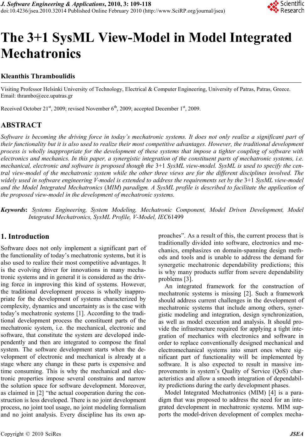 J. Software Engineering & Applications, 2010, 3: 109-118 doi:10.4236/jsea.2010.32014 Published Online February 2010 (http://www.SciRP.org/journal/jsea) Copyright © 2010 SciRes JSEA 109 The 3+1 SysML View-Model in Model Integrated Mechatronics Kleanthis Thramboulidis Visiting Professor Helsinki University of Technology, Electrical & Computer Engineering, University of Patras, Patras, Greece. Email: thrambo@ece.upatras.gr Received October 21st, 2009; revised November 6th, 2009; accepted December 1st, 2009. ABSTRACT Software is becoming the driving force in today’s mechatronic systems. It does not only realize a significant part of their functionality but it is also used to realize their most competitive advantages. However, the traditional development process is wholly inappropriate for the development of these systems that impose a tighter coupling of software with electronics and mechanics. In this paper, a synergistic integration of the constituent parts of mechatronic systems, i.e. mechanical, electronic and software is proposed though the 3+1 SysML view-model. SysML is used to specify the cen- tral view-model of the mechatronic system while the other three views are for the different disciplines involved. The widely used in software engineering V-model is extended to address the requirements set by the 3+1 SysML view-model and the Model Integrated Mechatronics (MIM) paradigm. A SysML profile is described to facilitate the application of the proposed view-model in the development of mechatronic systems. Keywords: Systems Engineering, System Modeling, Mechatronic Component, Model Driven Development, Model Integrated Mechatronics, SysML Profile, V-Model, IEC61499 1. Introduction Software does not only implement a significant part of the functionality of today’s mechatronic syste ms, but it is also used to realize their most competitive advantages. It is the evolving driver for innovations in many mecha- tronic systems and in general it is considered as th e driv- ing force in improving this kind of systems. However, the traditional development process is wholly inappro- priate for the development of systems characterized by complexity, dynamics and uncertainty as is the case with today’s mechatronic systems [1]. According to the tradi- tional development process the constituent parts of the mechatronic system, i.e. the mechanical, electronic and software, that constitute the system are developed inde- pendently and then are integrated to compose the final system. The software development starts when the de- velopment of electronic and mechanical is already at a stage where any change in these parts is expensive and time consuming. This is why the mechanical and elec- tronic properties impose several constrains and narrow the solution space for software development. Moreover, as claimed in [2] “the actual cooperation during the con- struction is less developed. There is no joint development process, no joint tool usage, no joint modeling formalism and no joint analysis. Every discipline has its own ap- proach es”. As a r esult of this, th e curren t process that is traditionally divided into software, electronics and me- chanics, emphasizes on domain-spanning design meth- ods and tools and is unable to address the demand for synergetic mechatronic dependability predictions; this is why many products suffer from severe dependability problems [3]. An integrated framework for the construction of mechatronic systems is missing [2]. Such a framework should address current challenges in the development of mechatronic systems that include among others, syner- gistic modeling and integration, design synchronization, as well as model execution and analysis. It should pro- vide the infrastructure required for applying a tight inte- gration of mechanics with electronics and software in order to replace conventionally designed mechanical and electromechanical systems into smart ones where sig- nificant part of functionality will be implemented by software. It is also expected to result in massive im- provements in system’s Quality of Service (QoS) char- acteristics and allow a smooth integration of dependabil- ity predictions during the early development phases. Model Integrated Mechatronics (MIM) [4] is a para- digm that was proposed to address the need for an inte- grated development in mechatronic systems. MIM sup- ports the model-driven development of complex mecha-  The 3+1 SysML View-Model in Model Integrated Mechatronics 110 tronic systems (MTSs) through the evolution of models that have as primary construct the mechatronic compo- nent (MTC). The concept of component has already been adopted in the development process of manufacturing systems by other researchers too. However, they mostly focus on the software part of the component; they do not address the whole development process; and they do not provide an architecture for the concurrent engineering of all constituent components, i.e., mechanical, electronic and software. In this paper, the Systems Modeling Language (SysML) [5] is adopted for the system’s modeling process in the MIM paradigm. An architectural view-model, the one called 3+1 SysML is proposed to address the synergistic integration of the constituent parts of mechatronic sys- tems. The main view is the SysML view that corresp onds to the mechatronic layer of the MIM Architecture. This view captures the system model that is the one con- structed by the MTS developer. Each of the three views is used to describe the system fro m the perspective of the corresponding discipline. Specific tools of every disci- pline may be exploited for the model execution and analysis of the SysML models. SysML is used to represent the models of the mecha- tronic system that are proposed by the MIM paradigm. A SysML profile was defined using Papyrus, an open source tool for graphical UML 2/SysML modeling. This profile supports not only the modeling of mechatronic systems using the concept of mechatronic component but also a hybrid development process that integrates the traditional approach with the MTC-based one, to allow the reuse of legacy systems. It provides a SysML based implementation of the MIM architecture that will allow the MIM paradigm to be exploited in the development process of real world mechatronic systems. An effective development process that exploits the 3+1 SysML view-model and the SysML profile is described extend- ing the well-known in software engineering V-model [6]. The remainder of this paper is organized as follows. In the next section, a brief introduction to the MIM archi- tecture and the SysML is given and the related work is briefly discussed. Section 3 presents the proposed 3+1 SysML view-model that emphasizes the importance of the common system-level model. In Section 4, a SysML profile that represents the artifacts used in the MIM ar- chitecture is described. Section 5 presents the proposed modifications to the widely used in software systems V-model to address the needs of the MTS development process. Future developments and research challenges are discussed in Section 6 and the paper is concluded in the last section. 2. Background and Related Work 2.1 A Brief Introduction to MIM The upper layer of the MIM architecture that is shown in Figure 1, i.e. the mechatronic layer, was defined to sys- tematically address complexities in the model-driven development process of component-based mechatronic systems. This layer is projected into three dimensions representing the application, the resource, and the me- chanical process respectively. The controlling application software is modeled in the application layer, while the hardware, i.e., computing and communication, as well as the software resources that constitute the infrastructure required for the execution of the controlling application software, are modeled in the resource layer. Mechanical, hydraulic and pneumatic parts are modeled in the me- chanical layer. Mechatronic system integrators work horizontally in the model evolution dimension of the MIM architecture. They interactively compose the MTS using already de- fined MTCs without worrying on lower layers’ imple- mentation details. They go through a model-driven de- velopment process to build the MTS using descriptions of already existing MTCs. They only have to capture the application logic in application layer components, as well as to identify their required QoS characteristics from the resource layer infrastructure. MTC builders work in the model integration dimen- sion and apply an information integration process that crosses the boundaries between mechanical, electronic, and computer science fields. They work horizontally and vertically, either top-down or bottom-up, in the lower three layers of the architecture in a concurrent way. Con- structed MTCs are stored in MTC repositories to be dis- covered and used by mechatronic system integrators [7]. MIM is a new paradigm that promotes model integra- tion not only of implementation space artifacts but also of early analysis and design phase ones. It promotes Figure 1. The Model Integrated Mechatronics (MIM) ar- chitecture [4] Copyright © 2010 SciRes JSEA  The 3+1 SysML View-Model in Model Integrated Mechatronics Copyright © 2010 SciRes JSEA 111 Figure 2. SysML diagrams and its comparison with UML 2 [5] The other new diagram, i.e. the parametric diagram, is used to describe the constraints among the properties associated with blocks. It allows the specification of co n- tinuous components by parametric constraints on class attribute values expressing corresponding differential equations. However, the syntax and the semantics of be- havioral descriptions captured in parametric diagrams have not been defined to allow the integration with other simulation and analysis modeling techniques for the proper execution of the models. So, the parametric dia- gram is used to integrate the system descriptive behavior and structure models expressed in SysML with other simulation and engineering analysis models such as per- formance, reliability, and mass property models. reuse at the mechatronic level and significantly decreases development and validation time of the system. MIM addresses the need for synergistic integration at the model and process levels; it facilitates the integration between the design processes of the different disciplines which is the approach considered as the most effective to improve the development process of mechatronic sys- tems. The other two approaches being: implementation time integration and design time integration at data and model level [8]. 2.2 Systems Modeling Language (SysML) SysML was developed to support the specification, analysis, design, verification and validation of a broad range of complex systems [5]. These systems may in- clude hardware, software, information, processes, per- sonnel, and facilities. The objective o f SysML is to unify the diverse modeling languages currently used by system engineers. SysML reuses a subset of UML 2 [9] and pro- vides additional extensions needed to address system engineering aspects not covered by UML 2. It includes diagrams that can be used to specify system requirements, behavior, structure and parametric relationships. Re- quirements diagram and parametric diagrams are the new diagram types proposed by SysML, as shown in Figure 2 which presents the diagrams that are used by SysML. The fact that SysML is based on UML 2, will allow system engineers modeling with SysML and software engineers modeling with UML 2 to collaborate on mod- els of the mechatronic system. This will improve com- munication among the various stakeholders who partici- pate in the mechatronic systems development process and will promote interoperability among modeling tools in different disciplines. All the above mentioned charac- teristics make SysML ideal for the representation of models used in the MIM paradigm. 2.3 Related Work SysML provides modeling constructs to represent text-based requirements and relate them to other model- ing elements. The requirement diagram can be used to represent many of the relationships that exist between requirements and visualize them. It provides a bridge between traditional requirements management tools and the other SysML models. It can be used to depict the requirements in graphical, tabular, or tree structure for- mat and highlight their relationships, as well as to cap- ture the relationships between requirements and other model elements that satisfy or verify them. Several researchers are already working in the direction of improving the effectiveness of the development proc- ess of mechatronic systems. Schafer and Wehrheim [2] survey on current developments in mechatronics and present the architecture of their mechatronic rail system that seems to provide an excellent platform for studding and analyzing future developments and research chal- lenges in mechatronic systems. They identify the need of an integrated framework for the construction of mechatronic systems and they discuss future trends in mechatronics especially from the software engineering  The 3+1 SysML View-Model in Model Integrated Mechatronics 112 point of view. Habib [10] argues on the urgen t need for theories, models, and tools that should facilitate model- ing, analysis, synthesis, simulation, and prototyping of mechatronic systems. He emphasizes the argument that the approach based on optimization within each do main separately will not result in the optimum system design, and he proposes a data and model integration approach to address the integration problem. Burmester et al. [11] claim that in today’s mechatronic systems most of the control and reconfiguration functionality is realized in software. They present mechatronic UML to exploit the Model Driven Architecture approach for the design of hybrid mechatronic real-time systems that have to fulfill safety-critical requirements. “Mechatronic UML” is defined as an extension of UML to built platform inde- pendent models for mechatronic systems. Various UML mode ls h ave b e en ex t ended to cover the req u ir e men ts o f modeling the structural view as well as the behavioral view of the system. However, the proposed extension is used to mod el only the sof tware part of the mech atronic system. Authors in [12] briefly refer to a process model of Robert Bosch GmbH for the development of mecha- tronic systems in Motor Vehicles to support aspects such as reuse, exchangeability, scalability and distrib- uted development. They use the concept of mechatronic component, even though not well defined, as the basic construct of their process. They argue: a) on the need of a clear specification of component interfaces; and b) the great contribution of re-use to increase the quality prop- erties of mechatronic systems and decrease develop- ment time. Nordmann [13] is using the concept of mechatronic component and presents an example of using Active Magnetic Bearings to increase perform- ance, reliability, reusability and longer lifetime. Authors in [14] propose for the development of multidiscipli- nary systems, such as mechatronics, the integration of the various domain-specific tools. They mainly focus on the integration of used data and models and not on a process level integration. Moreover, none of these ap- proaches provide a high level architecture for an inte- grated, synergistic development process for mecha- tronic systems and they do not describe a systems level development process based on the mechatronic compo- nent and the emerging standard in the domain that is SysML. 3. The 3+1 Architectural View Model Each of the three lower layers of the MIM architecture provides a specific view of the central models that are captured in the upper layer, i.e. the mechatronic layer. Each view is used to describe the system from the per- spective of the corresponding discipline. The software view (s-view), for example, provides the models of the software part of the MTS and allows for software spe- cific tools to be used to elaborate and further refine these models. The IEC61499 function block model is an ex- ample of such a domain specific model that can be used to further refine the s-view [15]. Figure 3 depicts the 3+1 SysML view-model that is proposed for the development of mechatronic systems. The MTS model is the heart of this architecture and is depicted in the center of the pic- ture. It is surrounded by 4 views which correspond to the roles that engineers play during the development process of mechatronic systems. The main view is the MTS-view that corresponds to the mechatronic layer of the MIM Architecture. This is the view that is used by the MTS developer. The other 3 views correspond to the 3 lower layers of the MIM ar- chitecture. The m-View, for example, corresponds to the Mechanical layer of the MIM architecture and cap- tures all the mechanics, hydraulics and pneumatics of the MTS model. These models are generated by pro- jecting the MTS models to the mechatronic layer and are fully synchronized with the MTS models. Any modifications imposed by the mechanical engineer to the models of this view directly affect the correspond- ing central MTS models. Moreover, modifications done by the MTS developer on the central models directly affect the corresponding m-view models. The m-view is mainly used during the primitive MTC development process where a concurrent, synergistic engineering on the three views is adopted at the primitive MTC level as a more eff ective pro cess. It is a lso used to have a whole view of the mechanical system model and perform op- timization and analysis activities on this. Figure 4 presents the structure of the primitive MTC and its interfaces to the environment. A primitive MTC may expose to the environment mechanical, electronic and software interfaces through the corresponding ports. Interfaces between its constituent parts are also shown. Sensors and actuators are used to realize the interactions Figure 3. The 3+1 SysML view-model for mechatronic sys- tems development Copyright © 2010 SciRes JSEA  The 3+1 SysML View-Model in Model Integrated Mechatronics113 Figure 4. The structure of the primitive mechatronic com- ponent between the mechanical part and the electronic one. This means that sensors and actuators are fully encap- sulated by the MTC construct. The mechanical part in- teracts with the environment only through mechanical ports that are mainly in the form of mounting ports or ports for flow of material or energy. A detailed descrip- tion of mechanical connections that can be discrimi- nated into fixed and moveable arrangements is given in [16]. The sOperatorPanel, i.e. the software part of the OperatorPanel primitive MTC, exposes its functionality along with the corresponding QoS through a provided interface of the sPort. A hosting functionality for appli- cation specific components will be optionally provided by the ePort. Currently there is no tool to execute the MTS models, not even to analyze their behavior. Discipline specific tools may be exploited for the execution and analysis of MTS models. This is obtained by the proper integration and coordination of specific model execution and analy- sis tools of the three views. The tool of each view is used to execute the primitive MTC model of its perspective so it has to provide specific interfaces to the tools of the other views, in order to implement the interactions of its own part to the other parts of the primitive MTC. The arrows that cross the boundaries between the three views in Figure 3 represent the interactions of the correspond- ing models and have to be implemented by specific in- terfaces of the model refinement, analysis and execution tools of the three disciplines. The AP233 or more for- mally the ISO 10303-233 standard for systems engineer- ing [17], that provides a data exchange format for the reliable interchange of data between software tools may be exploited to effectively implement these interactions. The execution and analysis of the primitive MTC is ob- tained through a collab oration of the correspond ing tools of the three views. It is clear that the contribution of the three views’ specific tools is restricted at the primitive MTC internal level while the execution and analysis of MTC models is done at the MTS level with the coordina- tion and synchronization between MTCs carried by this level. This makes the tool integration a major challenge in the domain of mechatronic systems. The 3+1 SysML view-model when used with the MTS V-Model that is described in one of the following sec- tions, promote the synergistic integration of the three constituent parts of the mechatronic system and empha- sizes the importance of a common model for the system. However, this model can also be used with the trad itional development process that is based on the independent development of constituent parts of the mechatronic sys- tem and their subsequent integration. Even in this case the existence of a common model for the system greatly improves the effectiveness of the development process. It should be noted that in each view the corresponding discipline’s specific architectures and tools may be ex- ploited, as for example the 4+1 architectural view [18] that may be exploited in the context of the e-view by the software engineer or the MTC developer/integrator. 4. Using SysML to Model the MIM Artifacts The Systems Modeling Language can be used to repre- sent the artifacts of the mechatronic systems develop- ment process that correspond to the system level activi- ties. These include requirements specifications for the MTS and MTC levels, as well as architectural specifica- tions for the MTS and MTC levels. UML 2.0 will be used for the modeling of the software part of the primi- tive MTC and corresponding tools from the electronics and mechanics domain will be used for the modeling of the other two constituent parts of the MTC. In this sec- tion the modeling of the MTS and MTC levels using SysML is considered. It is evident that specific interfaces have to be defined for the integration of the different views and these interfaces have to be realized by the tools used in the various disciplines to create a com- pletely integrated tool chain to support the MTS devel- opment process. The SysML to AP233 mapping [19] is towards this direction. 4.1 Modeling of the Mechatronic Component The MTS stereotype that is shown in Figure 5, which presents part of the SysML4MIM profile, is considered as a composition of MTSComponents and MTSConnec- tors (not shown in the figure). The abstract stereotype MTSComponet was defined to provide more flexibility in system modeling. It allows the definition of the dif- ferent disciplines’ components in any level of the sys- tem’s decomposition hierarchy; it also allows the appli- cation of the traditional approach where the system is considered as consisting of mechanical, electronic and software components. An MTSComponent that is ab- stract is specialized to the MTC abstract stereotype and the mCompoment, eComponent and sComponent stereo- ypes. The mComponent stereotype is used to represent t Copyright © 2010 SciRes JSEA  The 3+1 SysML View-Model in Model Integrated Mechatronics Copyright © 2010 SciRes JSEA 114 Figure 5. SysML4MIM profile (part); the MTS stereotype in the model any mechanical component of the mecha- tronic system. This way of modeling allows the profile to be used also in the traditional development process of mechatronic systems since the MTS may be considered as a composition of m, e and sComponents. The MTC stereotype which is also abstract is specialized to the CompositeMTC and the PrimitiveMTC. This allows a hierarchical decomposition scheme for the MTS up to the level of primitive MTC th at is considered as composition of m, e and sComponents. An m, e and sComponent may be further decomposed in corresponding Components allowing a component based synthesis in each one of the three disciplines. The SysML4UML profile that was cre- ated using Papyrus, an open source tool for graphical UML 2 modeling (http://www.papyrusum-l.org/), im- ports the UML4SysML profile that is already supported by Papyrus. This allows the MTS stereotype to extend the Block stereo type of the UML4 SysML profile. All the other components also extend the Block stereotype even not shown in figure. The proposed SysML4MIM profile allows the synergistic integration in the development of mechatronic systems to any level of granularity down to the primitive MTC component which is the one that is not decided or it is not possible to be decomposed into lower layer MTC components. 4.2 Modeling of the Mechatronic Port Allowable inputs and outputs of an MTC are defined using the concept of the port. This allows the design of modular reusable MTCs, with clearly defined interaction points and interfaces with the environment. The construct of Mechatronic port (MTPort) was defined as an exten- sion of the UML port to fulfill this requirement. SysML provides standard ports which support client-server communication and FlowPorts that define flows in and/or out of a block. An MTC may own MTPo rts, as shown in Figure 6, which allows the MTC to declare the items it may exchange with its environment and the interaction points through which this exchange is made. Furthermore, MTPorts allow the MTC to declare the provided to the environment services but also the services that the MTC expects from it. An MTPort is defined as an aggregation of mPort, ePort and sPort. Each port is used to represent the interaction point of the corresponding part of the primitive MTC with the environment (see Figure 4). All these ports extend the SysML port; mPort and ePort ex- tend it through the SysML flow port while sPort extends it directly. So, a sPort is characterized by provided and required interfaces. The specification of what can flow in or out of an mPort or ePort is achieved by typing them with a specification of the things that flow in and/or out. It should be noted that an mPort may accept or transmit energy or material but may also accept or transmit in- formation that has been decided to be transferred by me- chanical means. Of course the same information may be transferred by electronic signals using an ePort or by software messages using a sPort. The support of several alternatives through configuration, results in increased reuse potential for the MTC. The specification of the ervices of the sPort is achieved by typing it with the s  The 3+1 SysML View-Model in Model Integrated Mechatronics115 Figure 6. The MTPort stereotype in the SysML4MIM profile provided and/or required interfaces. Flows of mPorts and ePorts may be atomic or non atomic; an atomic flow is specified with a single type representing the items that flow in or out. A non atomic flow is specified with a flow specification which lists th e items that constitu te the flow. A sPort accepts software signals, i.e. packages of infor- mation, which usually need a more complicated specifi- cation supported by UML 2. 5. The MTS Development Process The MIM development process adopts the V-model as basis and updates it to address the needs of the mecha- tronic systems domain. Figure 7 presents the proposed MTS V-Model. A system modeling process is applied down to the primitive MTC level, as shown in the left-hand part of the V-model. For primitive MTCs that have to be constructed, a concurrent engineering process of all three constituent parts, i.e., mechanics, electronics and software is adopted, as depicted in the bottom of the V-Model. The system integration and verification process is depicted by the right-hand side of the V-model. MTS-level requirements are captured using the SysML requirements diagram. Essential use cases, which are used to capture the functional requirements at this level, are defined in abstract, simplified, and independent of technology or implementation way. They are written as “an abstract dialog representing user intentions and sys- tem responsibilities, and they are typically small and fo- cused on a highly specific user goal, yielding a fine- grained model of user activity” [20]. After the definition of the essential use cases there are two alternatives to proceed in the system’s architecture definition phase: 1) Use cases are decomposed in sub-use cases. 2) Responsibilities of the system are identified. In the first case the decomposition of use cases to sub-use cases allows: a) the reuse of existing components on the basis of their requirement specifications that should have been defined in terms of use cases, and b) modularity and reuse in requirements specification arti- facts. In the second case, activity diagrams are defined for each use case in order to identify the activi- ties/responsibilities of the actors and the ones that are required by the system in the context of the specific use case. After this step the list of abstract activities (func- tions) that have to be performed by the system is avail- able. In other words the responsibilities of the system in Copyright © 2010 SciRes JSEA  The 3+1 SysML View-Model in Model Integrated Mechatronics 116 Figure 7. The mechatronic system V-Model (MTS V-Model) the context of the specific use case are defined. The term responsibility is used to emphasize the fact that only the abstract definition of the activity/function is provided at this time and not its implementation. As a next step, for both alternatives, a system compo- sition should be proposed to satisfy either the system use-cases or the system responsibilities. Some use cases or system responsibilities may be directly supported by existing mechatronic components. However, it is com- mon that for a required system level use case or respon- sibility, a collaboration of MTCs has to be defined in order to achieve it. The system level use cases and sub-use cases or the system responsibilities/functions correspondingly are mapped to system’s components. An analogous mapping applies also for the non-functional requirements. The definition of system’s structure in terms of MTCs is a design process and results in the selection of system components and the definition of their collaboration. Furthermore each MTC has assigned responsibilities that are handled in the subsequent phases as its required re- sponsibilities. The result in both cases is a system archi- tecture that is comprised of: a) Class or component diagrams to specify the struc- ture of the system; b) Sequence or activity diagrams (or even state charts) to specify the components’ collaborations to provide the higher layer functionality. Domain analysis is used to capture the domain key concepts and provide the information required to create the first architectural model of the system. SysML dia- grams are used to specify the proposed architecture. Block definition diagrams (bdd) are used to capture the structure of the system and internal block diagrams (ibd) are used to capture the components’ interactions, all ex- pressed using the SysML4MIM profile. During the architecture definition the developer has to assign the system required responsibilities to the sys- tem’s components. This assignment results to an archi- tectural diagram that represents the system components, their responsibilities and the components interactions. The allocation relationship of SysML provides an effec- tive means to capture this assignment and allow the navigation between the system models by establishing cross-cutting relationships among them. There are two alternatives to proceed in the definition of the architec- ture: 1) The bottom-up approach (synthesis). 2) The top-down (decomposition). According to the bottom-up approach, for every sys- tem-level responsibility a set o f commercial off-the-shelf (COTS) MTCs is selected. We assume that each COTS MTC has its own provided functions that are well de- fined by the developer of the MTC [7]. These provided functions are part of the MTC package that specifies the real world MTC. QoS characteristics are also included in the MTC package and can be used to examine if the QoS aspects of the proposed collaboration scheme satisfy the required system-level QoS aspects for the specific re- sponsibility. If the QoS characteristics of this specific collaboration meet the QoS requirements of the sys- tem-level required responsibility, the design is accepted. Either wise corrective actions should be proposed and analyzed. Corrective actions may include: a) re-engineering of the collaboration scenario, b) the use of components with better QoS characteristics than the ones used in the previous design, or c) a combination of the above. It is assumed that the MTC developer has already performed a QoS analysis for the MTC. All this information com- prises the offered QoS characteristics of the MTC [4]. It should also be stated that the MTC developer does not know during the MTC’s development time all the sys- tems that this MTC will be used in the future. According to the top-down approach, for every sys- tem-level responsibility that has not been assigned to a single MTC, a set of abstract MTCs is defined and the required MTC responsibilities are specified along with the required collaboration sche me. Required system-level QoS characteristics are decomposed to derive the com- ponent-level required QoS characteristics. This process results to the definition of the required QoS characteris- tics at the level of constituent MTCs. The process of de- riving MTC-level QoS characteristics from system-level ones is a complex process and has to be defined. At this time the engineer has well defined required specifications (functional and non functional, including QoS character- istics) for every abstract MTC. Using these required QoS characteristics the engineer is able to select from the market or his components repository the ones that their offered QoS characteristics meet the required ones [8]. If such MTC’s do not exist they h ave to be further an alyzed in order to be developed. Advantages and disadvantages for the above ap- proaches that result in th e definitio n of the arch itecture of the MTS of its composite MTCs may be identified but it is expected that in the real MTS development process a Copyright © 2010 SciRes JSEA  The 3+1 SysML View-Model in Model Integrated Mechatronics117 combination of both approaches will be used resu lting to a hybrid more efficient approach. The above process, bottom-up or top-down, is again applied to every composite MTC that has to be devel- oped. It is applied iteratively down to th e primitive-MTC level; the identification of primitive MTCs signals the end of this iteration. For each composite MTC the system modeling process as defined by the left-hand side part of the V-Model is followed. Analysis is applied and its ar- chitecture is defined in terms of constituent components (composite and/or primitive). Sequence diagrams are defined to realize use cases of the MTC and identify the activities that are involved in the specific use case. This is not the case for primitive MTCs that have to bypass the system process and follow a synergistic integration of the three constituent parts, i.e. mechanic, electronic and software (MTC synthesis) as shown in the bottom of the V-model in Figure 7. For each primitive MTC, verification follows its inte- gration as shown in the right-hand side of the MTS V-Model. Each composite MTC is integrated according to its MTC architecture and then it is verified against its requirements. After the integration and verification of the MTCs of the system, the MTS integration test is per- formed and the MTS is verified against its requirements. It should be noted that the system analysis phase is followed by a system architecture design phase as shown in the proposed MTS V-model. This is also the case for the V-Model in software engineering. After this point th e proposed V-model is completely differentiated from the traditional software engineering V-model. After the sys- tem architectural design, repetitions of analysis followed by architecture design for every composite MTC are ap- plied following the system modeling process up to the primitive MTC level. This is the point where the system development process is terminated and the synergistic integration of constituent parts of the primitive MTC is performed working independently but in a synergistic way in the three disciplines. For every primitive MTCs that has complex software constituent part, a software V-model can be applied for its development, as shown in the bottom of the MTS V-Model. Figure 8 presents two real world MTCs and the Paral- lel Kinematic Machine evolium MTS, that were devel- oped based on the basic principles of the MIM architec- ture by a high-tech Italian company. Each axis of the Parallel Kinematic Machine has its own intelligence, so there is no need of an external entity to control the mo- tion trajectory. 6. Future Developments and Research Challenges Mechatronic systems development is a very complicated process imposing many challenges. In this section we refer to the ones that are of higher priority considering the 3+1 SysML view-model. The identification of the Figure 8. Real-world MTS and MTCs mechanical discipline information that has to be captured in the system level models is one of the challenges. There are two possible approaches: a) exploit SysML constructs to represent as much of the mechanical discipline infor- mation, including component interfaces and behavior; and b) extend SysML constructs with new ones with the objective of creating a complete SysML model of the mechanical component. In the first case specific tools will be used for further refinement of the mechanical models and their subsequent execution and analysis. In the latter, the SysML models have to be automatically transformed to models of the specific tools for execution and model analysis. The integration of SysML with the Modelica language (www.modelica.org/) is towards this direction. This challeng e is greatly related to the one that concerns the model execution, analysis and assessment of models on the MTS-view level. Fully automated generation of the three views from the MTS view, as well as automatic update of the MTS-view with changes in the discipline views are important chal- lenges that have to be addressed to improve the effec- tiveness of the process. This also imposes the challenge of integration of existing mechanical and electronic do- main design tools. The identification and definition of reusable MTCs is another major challenge in mechatronic systems. The Workpartner [21], a mobile service robot, is planned to be used in the context of a TEKES (Finnish Funding Agency for Technology and Innovation) funded project as a case study for the application of MIM, but also as a case study for the iden tification of reusable MTCs. Since many of the MTSs are from the safety critical domain, the integration of the MTS V-model development process and the 3+1 SysML view-model with safety engi- neering is another major challenge for the MIM paradigm to be effectively exploited in safety- critical mechatronic systems. 7. Concluding Remarks The traditional approach in the development of mecha- tronic systems is unable to address the needs of today’s Copyright © 2010 SciRes JSEA  The 3+1 SysML View-Model in Model Integrated Mechatronics Copyright © 2010 SciRes JSEA 118 complex mechatronic systems. An integrated framework for the construction of mechatronic systems is missing. The work presented in this paper attempts to contribute to this direction by: a) using SysML to define the arti- facts of the MIM paradigm; b) propo sing the 3+1 SysML view-model imposed by the MIM architecture; and c) extending the well accepted and widely used in the soft- ware domain V-model to address the demands of the mechatronic system development process. However, the challenges for a fully automated MTS development process crosses the boundaries of the three disciplines of mechatronic systems and impose a joint effort and col- laboration between computer science, electronics and mechanics. The current status of discipline isolation im- posed in many cases by the existing structure of engi- nee ring d egre e progr ams ma kes t he tas k even mo re co m- plicated. 8. Acknowledgments Part of this work has been funded by TIKOSU, a project belonging to the Digital Product Process -program of the Finnish Funding Agency for Technology and Innovation (TEKES). The author wishes to thank the partners and especially Jarmo Alanen, Kari Koskinen, and Seppo Sierla for fruitful comments on these ideas. Thanks are also due to Piero Larizza, Eric Coatanea and Jussi Suomela for discussions on these concepts. REFERENCES [1] G. Rzevski, “On conceptual design of intelligent mecha- tronic systems,” Mechatronics, 2003. [2] W. Schafer and H. Wehrheim, “The challenges of build- ing advanced mechatronic systems,” Future of Software Engineering, International Conference on Software Engi- neering, IEEE Computer Society, 2007. [3] Philipp Limbourg, “Dependability modelling under un- certainty: An imprecise probabilistic approach,” Springer, 2008. [4] K. Thramboulidis, “Model integrated mechatronics: To- wards a new paradigm in the development of manufac- turing systems,” IEEE Transactions on Industrial Infor- matics, Vol. 1, No. 1, February 2005. [5] OMG, “OMG Systems Modeling Language (OMG SysML™),” V1.0, September 2007. [6] GD250, “Lifecycle process model ‘V-Model’,” Available online: http://www.informatik.uni-bremen.de/gd-pa/vmodel/ vm1. htm#application [7] K. Thramboulidis, G. Doukas, and G. Koumoutsos, “A SOA-based embedded systems development environment for industrial automation,” EURASIP Journal on Embed- ded Systems, Article ID 312671, pp. 15, 2008. [8] K. Thramboulidis, “Challenges in the development of mechatronic systems: The mechatronic component,” 13th IEEE International Conference on Emerging Technolo- gies and Factory Automation (ETFA), Hamburg, Ger- many, September 2008. [9] OMG, “Unified modeling language: Superstructure,” version 2.1.1, formal/2007-02-03. [10] M. Habib, “Mechatronics,” IEEE Industrial Electronics Magazine, Vol. 1, No. 2, Summer 2007. [11] S. Burmester, H. Giese, and M. Tichy, “Model-driven development of reconfigurable mechatronic systems with mechatronic ‘UML’ in model driven architecture,” Springer Berlin/Heidelberg, Vol. 3599, 2005. [12] K. Knorr, A. Lapp, P. Torre Flores, J. Schirmer, D. Kraft J. Petersen, M. Bourhaleb, and T. Bertram “A process model for distributed development of networked mecha- tronic components in motor vehicles,” Proceedings of the IEEE Joint International Conference on Requirements Engineering (RE’02), 2002 [13] R. Nordmann, “Use of mechatronic components in rotat- ing machinery,” Book: Vibration Problems ICOVP 2005, Springer Netherlands, Vol. 111, January 20, 2007. [14] J. El-khoury, O. Redell, and M. Torng ren, “A tool integra- tion platform for multi-disciplinary development,” Pro- ceedings of the 2005 31st EUROMICRO Conference on Software Engineering and Advanced Applications, 2005. [15] G. Doukas and K. Thramboulidis, “A real-time Linux based framework for model-driven engineering in control and automation,” IEEE Transactions on Industrial Elec- tronics (forthcoming). [16] G. Pahl, W. Beitz, J. Feldhusen, and K. H. Grote, “Engi- neering design: A systematic approach,” Third Edition, Springer-Verlag London, 2007. [17] R. Eckert, W. Mansel, and G. Specht, “Model transfer among CASE tools in systems engineering,” Systems En- gineering, Vol. 8, No 1, pp. 41–50, March 2005. [18] P. Kruchten, “The 4+1 view model of architecture,” IEEE Software, Vol. 12, No. 6, pp. 42–50, November 1995. [19] OMG, “SysML and AP233 mapping activity,” OMG SysML portal, http://www.omgwiki.org/OMGSysML/ doku. php?id=sysml-ap233:mapping_between_sysml_and_ap233. [20] L. Constantine, “Activity modeling: Toward a pragmatic integration of activity theory with usage-centered design,” Technical Paper, Available on-line: http://www. foru se. com/ articles/activitymodeling.pdf [21] “The workpartner mobile service robot,” http://automa- tion.tkk.fi/ |