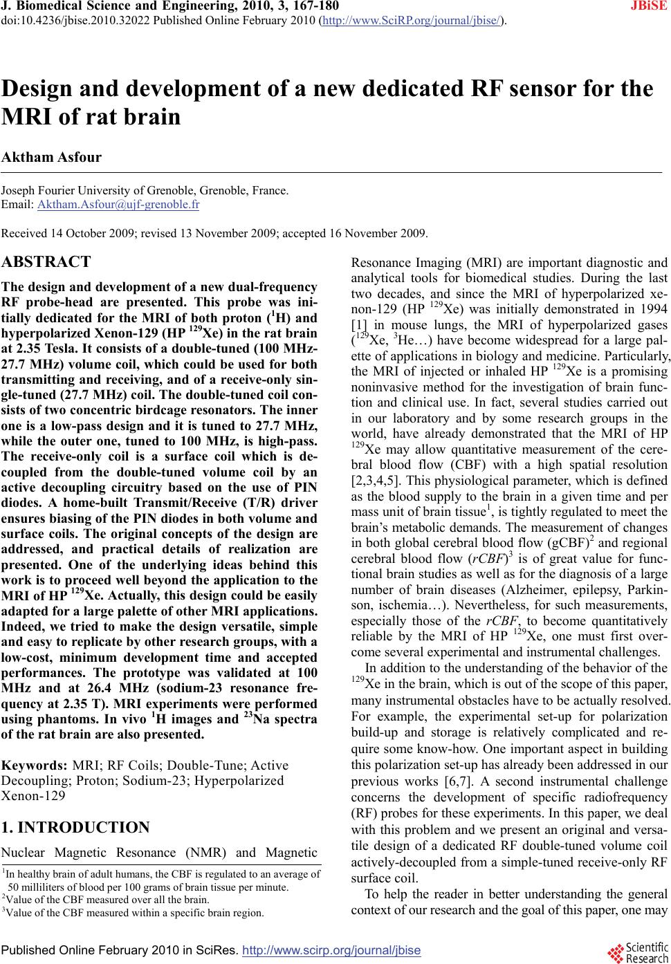
 J. Biomedical Science and Engineering, 2010, 3, 167-180 doi:10.4236/jbise.2010.32022 Published Online February 2010 (http://www.SciRP.org/journal/jbise/ JBiSE ). Published Online February 2010 in SciRes. http://www.scirp.org/journal/jbise Design and development of a new dedicated RF sensor for the MRI of rat brain Aktham Asfour Joseph Fourier University of Grenoble, Grenoble, France. Email: Aktham.Asfour@ujf-grenoble.fr Received 14 October 2009; revised 13 November 2009; accepted 16 November 2009. ABSTRACT The design and development of a new dual-frequency RF probe-head are presented. This probe was ini- tially dedicated for the MRI of both proton (1H) and hyperpolarized Xenon-129 (HP 129Xe) in the rat brain at 2.35 Tesla. It consists of a double-tuned (100 MHz- 27.7 MHz) volume coil, which could be used for both transmitting and receiving, and of a receive-only sin- gle-tuned (27.7 MHz) coil. The double-tuned coil con- sists of two concentric birdcage resonators. The inner one is a low-pass design and it is tuned to 27.7 MHz, while the outer one, tuned to 100 MHz, is high-pass. The receive-only coil is a surface coil which is de- coupled from the double-tuned volume coil by an active decoupling circuitry based on the use of PIN diodes. A home-built Transmit/Receive (T/R) driver ensures biasing of the PIN diodes in both volume and surface coils. The original concepts of the design are addressed, and practical details of realization are presented. One of the underlying ideas behind this work is to proceed well beyond the application to the MRI of HP 129Xe. Actually, this design could be easily adapted for a large palette of other MRI applications. Indeed, we tried to make the design versatile, simple and easy to replicate by other research groups, with a low-cost, minimum development time and accepted performances. The prototype was validated at 100 MHz and at 26.4 MHz (sodium-23 resonance fre- quency at 2.35 T). MRI experiments were performed using phantoms. In vivo 1H images and 23Na spectra of the rat brain are also presented. Keywords: MRI; RF Coils; Double-Tune; Active Decoupling; Proton; Sodium-23; Hyperpolarized Xenon-129 1. INTRODUCTION Nuclear Magnetic Resonance (NMR) and Magnetic Resonance Imaging (MRI) are important diagnostic and analytical tools for biomedical studies. During the last two decades, and since the MRI of hyperpolarized xe- non-129 (HP 129Xe) was initially demonstrated in 1994 [1] in mouse lungs, the MRI of hyperpolarized gases (129Xe, 3He…) have become widespread for a large pal- ette of applications in biology and medicine. Particularly, the MRI of injected or inhaled HP 129Xe is a promising noninvasive method for the investigation of brain func- tion and clinical use. In fact, several studies carried out in our laboratory and by some research groups in the world, have already demonstrated that the MRI of HP 129Xe may allow quantitative measurement of the cere- bral blood flow (CBF) with a high spatial resolution [2,3,4,5]. This physiological parameter, which is defined as the blood supply to the brain in a given time and per mass unit of brain tissue1, is tightly regulated to meet the brain’s metabolic demands. The measurement of changes in both global cerebral blood flow (gCBF)2 and regional cerebral blood flow (rCBF)3 is of great value for func- tional brain studies as well as for the diagnosis of a large number of brain diseases (Alzheimer, epilepsy, Parkin- son, ischemia…). Nevertheless, for such measurements, especially those of the rCBF, to become quantitatively reliable by the MRI of HP 129Xe, one must first over- come several experimental and instrumental challenges. In addition to the understanding of the behavior of the 129Xe in the brain, which is out of the scope of this paper, many instrumental obstacles have to be actually resolved. For example, the experimental set-up for polarization build-up and storage is relatively complicated and re- quire some know-how. One important aspect in building this polarization set-up has already been addressed in our previous works [6,7]. A second instrumental challenge concerns the development of specific radiofrequency (RF) probes for these experiments. In this paper, we deal with this problem and we present an original and versa- tile design of a dedicated RF double-tuned volume coil actively-decoupled from a simple-tuned receive-only RF surface coil. 1In healthy brain of adult humans, the CBF is regulated to an average of 50 milliliters of blood per 100 grams of brain tissue per minute. 2Value of the CBF measured over all the brain. 3Value of the CBF measured within a s ecific brain re ion. To help the reader in better understanding the general context of our research and the goal of this paper, one may 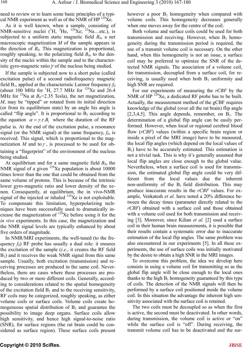 A. Asfour / J. Biomedical Science and Engineering 3 (2010) 167-180 Copyright © 2010 SciRes. 168 JBiSE need to review or to learn some basic principles of a typi- cal NMR experiment as well as of the NMR of HP 129Xe. As it is well known, when a sample, consisting of NMR-sensitive nuclei (1H, 3He, 129Xe; 23Na…etc.), is subjected to a uniform static magnetic field B0, a net macroscopic magnetization M of the sample appears in the direction of B0. This magnetization is proportional, roughly speaking, to the polarizing field B0, to the den- sity of the nuclei within the sample and to the character- istic gyro-magnetic ratio of the nucleus being studied. If the sample is subjected now to a short pulse (called excitation pulse) of a second radiofrequency magnetic field B1, applied at the characteristic Larmor frequency f0 (about 100 MHz for 1H, 27.7 MHz for 129Xe and 26.4 MHz for 23Na at B0=2.35 Tesla), the net magnetization, M, may be “tipped” or rotated from its initial direction (or from its equilibrium state) by an angle his angle is called “flip angle”. It is proportional to B1 according to the equation 1 ..B where the duration of the RF pulse is. At the end of the excitation pulse, a resonance signal (or the NMR signal) at the same frequency, f0, is received. This signal, which is proportional to the mag- netization M and to , is processed to be used for ob- taining a “fingerprint” of the environment of the nucleus being studied. At equilibrium and for a same magnetic field B0, the NMR signal of a given 129Xe population is about 10000 times lower than the one that could be obtained from the same volume of protons. This is because of the intrinsic lower gyro-magnetic ratio and lower density of the xe- non. Consequently, at equilibrium, the in vivo-NMR signal of the injected or inhaled 129Xe is not exploitable. To compensate this limitation, hyperpolarizing tech- niques have been successfully used to dramatically in- crease the magnetization of 129Xe before using it for the in vivo experiments. In this case, the magnetization and the NMR signal levels are typically enhanced by about five orders of magnitude. In NMR/MRI experiments, the well-tuned (to the fre- quency f0) RF probe has usually a dual role: it ensures the excitation of the sample (i.e., it creates the RF field B1) and it receives the weak NMR signal from this same sample. Usually, both excitation (transmission) and re- ceiving processes are produced in the same coil. Never- theless, there are cases where these processes are pro- duced by two or more different coils. Generally, accord- ing to considerations related to the spatial homogeneity of the excitation field B1 and to the receiving sensitivity, RF coils may be categorized, roughly speaking, as either volume coils or surface coils. Volume coils create ho- mogeneous spatial distribution of B1 and guarantee the possibility to image deep organs. Surface coils allow high sensitivity, and hence high signal-to-noise ratio (SNR), for surface regions (the rat brain could be con- sidered as surface region). These surface coils present however a poor B1 homogeneity when compared with volume coils. This homogeneity decreases generally when one moves away for the centre of the coil. Both volume and surface coils could be used for both transmission and receiving. However, when B1 homo- geneity during the transmission period is required, the use of a transmit volume coil is necessary. On the other hand, when this homogeneity is not an issue, a surface coil may be preferred to optimize the SNR of the de- tected NMR signals. The association of a volume coil, for transmission, decoupled from a surface coil, for re- ceiving, is usually used when both B1 uniformity and high SNR are required. For our experiments of measuring the rCBF by the NMR of HP 129Xe, a dedicated RF probe has to be built. Actually, the measurement method of the gCBF requires knowledge of the global (over all the rat brain) flip angle [2,3,4,5]. This angle depends, remember, on B1. The determination of a global flip angle can be easily per- formed. However, when local or regional cerebral blood flow (rCBF) values (within a specific brain region or inside a pixel of the MRI image) have to be measured, the local flip angles (which depend on the local values of B1) have to be accurately estimated. This estimation is not a trivial task. This is why it’s generally assumed that local flip angles are close enough to the global value. Nevertheless, when a surface coil is used for transmis- sion, the estimated global flip angle could be very dif- ferent from the local values due the inherent non-uniformity of the B1 field distribution. This may produce inaccurate results in the rCBF values. For ex- ample, Venkatesh et al. have noted a 20% difference be- tween the decay times (parameter directly related to the rCBF) obtained with a surface coil and those obtained with a volume coil used for both transmission and receiv- ing [3]. Moreover, since Kilian et al. [2] used a surface coil in their human brain measurements, it is possible that their results contain a systematic error due to inaccurate estimation of the local flip angles. The same problem was also encountered in our experiments [5]. In all these ex- periments, the use of surface coils was initially motivated by the desire to obtain a high SNR in the MRI images. To overcome this problem, the idea we develop here consists in using a volume coil for transmitting so as the global flip angle will be close enough to the local ones thanks to the high B1 homogeneity guaranteed by this type of coils. The detection of the NMR signals will then be performed by a surface coil positioned inside the volume coil. In this situation the advantage the inherent high sen- sitivity associated with the surface coil is retained. The two coils must be decoupled so as when the first is active, the second must be deactivated. In other words, during transmission, the volume coil is active or “on” while the surface coil is “off”. During receiving, the transmit volume coil has to be deactivated and the sur-  A. Asfour / J. Biomedical Science and Engineering 3 (2010) 167-180 Copyright © 2010 SciRes. 169 JBiSE face one has to be active. Both transmit and receive coils must be well-tuned to the resonance frequency of 129Xe (27.7 MHz at 2.35 T). Moreover, for the rCBF measurements by MRI, the fi- nal “ideal” probe must satisfy more stringent requirements. Actually, in addition to the transmission and receiving at the frequency of 129Xe, one has to be able to perform 1H-MRI experiments (at 100 MHz) without changing the probe and without moving the sample under test (rat in our application). In fact, acquiring 1H images is necessary to localize anatomical structures in the rat brain. These anatomical images are to be superposed to 129Xe images to identify structures where inhaled or injected 129Xe could be localized in the rat brain. On the other hand, the pro- cedure of homogenization of the static magnetic field (shimming), which is essential before every MRI acquisi- tion, must be performed using 1H NMR signals. Actually, since this shimming procedure requires repetitive excita- tions and detections, it can not be accomplished on the 129Xe signals because the artificial magnetization (non equilibrium state) of the HP 129Xe is not renewable when destroyed by an RF excitation pulse. In both anatomical image acquisition and shimming procedures, a high SNR of the detected 1H signals is not an issue and a same transmit-receive volume coil tuned to 100 MHz could be adequate. This coil must however be decoupled from both transmit volume and receive- only 129Xe coils. To summarize: the final “ideal” NMR probe that we developed consists of a transmit volume coil actively decoupled from a receive-only surface coil working at 27.7 MHz, and a transmit/receive volume coil for the 1H MRI at 100 MHz. The decoupling between the 1H coil and the 129Xe coils will be performed geometrically. This novel configuration, which actually associates three MRI coils in a same probe, is new and has not been published. In fact, due to the variety of size and experi- mental protocols encountered with small-animal imaging experiments, it is usually advisable and may be neces- sary to build a probe optimized for each experimental set-up and for each application. However, it is important to notice here that another objective of this work is to proceed well beyond this specific application to the MRI of HP 129Xe. Actually, the current design could be adapted or could inspire other designs for a palette of MRI applications in the rat brain. Generally, for such applications, the “ideal” imaging/spectroscopy coil would be one which provides high sensitivity, high B1 homogeneity, and operation on two or more frequencies without retuning requirement or cables changes. The problem of sensitivity can be addressed using surface coils [8]. The homogeneity requirements can be met by the use of adequate coil geometry (i.e., birdcage design [9]). The problem of acquiring data from two different nuclei (usually proton and a second nucleus like 129Xe, 23Na sodium, 31P…) requires the use of an efficient dou- ble-tuned coil (volume or surface coils) [10,11,12,13,14, 15,16,17]. While these problems have been addressed individually, there have been no published designs that have integrated all these features into one design. The goal of this work is to approach performances as out- lined above. Another underlying idea is to make this specific probe easy to replicate, by other research groups with a low-cost, minimum development time and ac- cepted performances. To allow for easy extension of this design to other frequencies (nuclei) and dimensions, we describe in some details the practical aspects of the workbench design as well as the coil characterization and MRI/NMR testing using phantoms. The probe is validated at the 1H frequency and the sodium frequency (26.4 MHz at 2.35 T) since this last is very close to the xenon frequency. In vivo MRI images of the rat brain were obtained at 1H frequency as well as NMR signals at the sodium frequency. All developed circuits and any other details on devel- oped probe could be obtained by simply writing to au- thors. 2. MATERIALS AND METHODS 2.1. The Double-Tuned Volume Probe We built a double-tuned volume probe using the bird- cage design [9]. This design ensures inherent high B1 homogeneity within the coil region. It is therefore well-suited for the MRI of HP 129Xe. The design is shown in its low-pass and high-pass versions in Figure 1. It consists of two circular loops, referred to as end-rings, connected by a number of equally spaced straight seg- ments referred to as legs or rungs. Depending on the version, the tuning capacitors are placed in the legs (low-pass) or in the end-rings (high-pass). A single-tuned birdcage will resonate in several modes. A birdcage with N legs has N/2 resonance modes (assuming N is even) [9,17], with the most useful to MRI being Mode 1 (fundamental mode). In this mode, the currents in the legs follow a cosine distribution as one moves radially around the coil. This sinusoidal dis- tribution of currents is essential to create a very ho- mogenous transverse magnetic field B1. For our application, it is necessary to double-tune the birdcage. The sinusoidal optimum current distribu- tion should be maintained at each frequency. Double- tuning a birdcage resonator is not a trivial task and it has been subject of many publications [10,11,12,13,17]. The method to choose depends actually on the desired per- formances at each frequency. Double-tuned birdcages have been used at relatively low field ( T). Few designs at higher fields have been proposed. For exam- ple, Fitzsimmons et al. [10] presented a double-tuned birdcage coil at 2 T. It was dedicated for the MRI of proton (85.5 MHz) and the NMR spectroscopy of phos- 5.1  A. Asfour / J. Biomedical Science and Engineering 3 (2010) 167-180 Copyright © 2010 SciRes. 170 Each resonator consists of eight legs. This number represents a compromise between B1 homogeneity and complexity of realization. The inner coil, a low-pass bir- dcage, had a diameter of 9 cm, a length of 13 cm, and was tuned to the xenon frequency. The outer coil, a high-pass design, had a length of 16 cm, a diameter of 10.5 cm, and was tuned to the proton frequency. We verified that no proton resonance modes occur at the xenon frequency. Conversely, no xenon modes occur at the proton frequency. The inner birdcage was rotated within the outer birdcage until minimum coupling oc- curred. This positioned the legs of the inner coil midway between the legs of the outer one. Also, the outer bird phorus (34.6 MHz) of the rat abdomen. They derived their coil in quadrature operation for both proton and phosphorus channels. The coil was used for both trans- mission and receiving at each frequency. One of the originalities of the double-tuned birdcage that we pro- pose here is that it has to work at higher field (2.35 T) for the MRI of the rat brain. More important is the fact that, to the knowledge of the author, a double-tuned birdcage associated with an actively decoupled receive- only surface coil has not been published. The double-tuned birdcage we built consists of two birdcages in a concentric configuration as it is seen in Figure 2. Figure 1. Spatial representation of the low-pass (left) and high-pass (right) birdcage resonators. CH (high-pass) and CL (low-pass) are the tuning capacitors. Figure 2. A simplified scheme of the developed imbricate birdcage resonators. The inner coil is low-pass and the outer one is high-pass. In linear polarization operation, the coils should be derived in such a way that their B1 fields are orthogonal allowing efficient geometric decoupling between the resonators. JBiSE 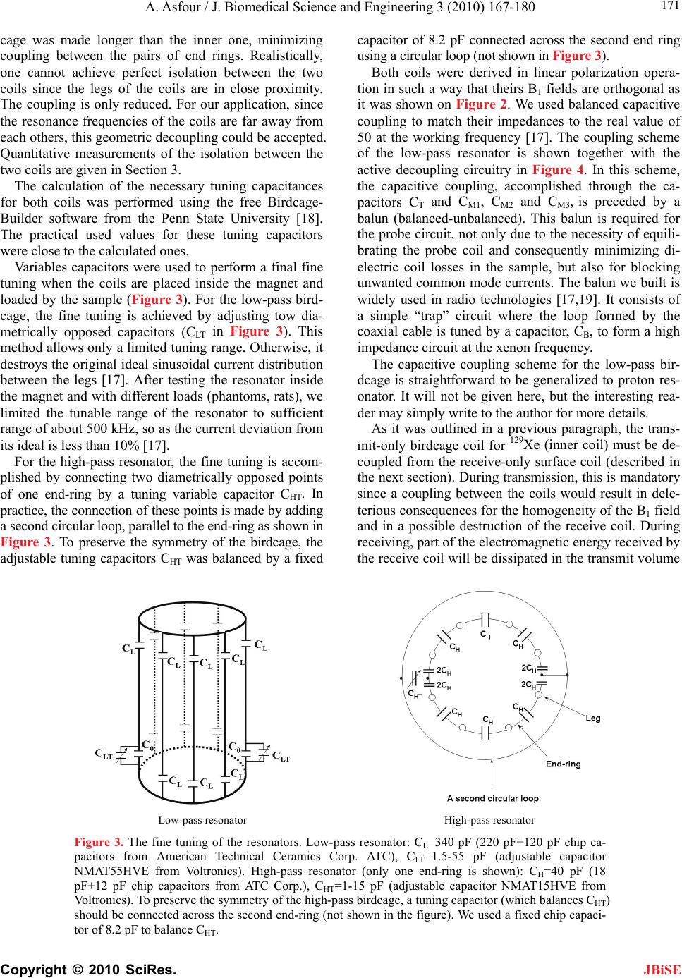 A. Asfour / J. Biomedical Science and Engineering 3 (2010) 167-180 Copyright © 2010 SciRes. 171 JBiSE cage was made longer than the inner one, minimizing coupling between the pairs of end rings. Realistically, one cannot achieve perfect isolation between the two coils since the legs of the coils are in close proximity. The coupling is only reduced. For our application, since the resonance frequencies of the coils are far away from each others, this geometric decoupling could be accepted. Quantitative measurements of the isolation between the two coils are given in Section 3. The calculation of the necessary tuning capacitances for both coils was performed using the free Birdcage- Builder software from the Penn State University [18]. The practical used values for these tuning capacitors were close to the calculated ones. Variables capacitors were used to perform a final fine tuning when the coils are placed inside the magnet and loaded by the sample (Figure 3). For the low-pass bird- cage, the fine tuning is achieved by adjusting tow dia- metrically opposed capacitors (CLT in Figure 3). This method allows only a limited tuning range. Otherwise, it destroys the original ideal sinusoidal current distribution between the legs [17]. After testing the resonator inside the magnet and with different loads (phantoms, rats), we limited the tunable range of the resonator to sufficient range of about 500 kHz, so as the current deviation from its ideal is less than 10% [17]. For the high-pass resonator, the fine tuning is accom- plished by connecting two diametrically opposed points of one end-ring by a tuning variable capacitor CHT. In practice, the connection of these points is made by adding a second circular loop, parallel to the end-ring as shown in Figure 3. To preserve the symmetry of the birdcage, the adjustable tuning capacitors CHT was balanced by a fixed capacitor of 8.2 pF connected across the second end ring using a circular loop (not shown in Figure 3). Both coils were derived in linear polarization opera- tion in such a way that theirs B1 fields are orthogonal as it was shown on Figure 2. We used balanced capacitive coupling to match their impedances to the real value of 50 at the working frequency [17]. The coupling scheme of the low-pass resonator is shown together with the active decoupling circuitry in Figure 4. In this scheme, the capacitive coupling, accomplished through the ca- pacitors CT and CM1, CM2 and CM3, is preceded by a balun (balanced-unbalanced). This balun is required for the probe circuit, not only due to the necessity of equili- brating the probe coil and consequently minimizing di- electric coil losses in the sample, but also for blocking unwanted common mode currents. The balun we built is widely used in radio technologies [17,19]. It consists of a simple “trap” circuit where the loop formed by the coaxial cable is tuned by a capacitor, CB, to form a high impedance circuit at the xenon frequency. The capacitive coupling scheme for the low-pass bir- dcage is straightforward to be generalized to proton res- onator. It will not be given here, but the interesting rea- der may simply write to the author for more details. As it was outlined in a previous paragraph, the trans- mit-only birdcage coil for 129Xe (inner coil) must be de- coupled from the receive-only surface coil (described in the next section). During transmission, this is mandatory since a coupling between the coils would result in dele- terious consequences for the homogeneity of the B1 field and in a possible destruction of the receive coil. During receiving, part of the electromagnetic energy received by the receive coil will be dissipated in the transmit volume Low-pass resonator High-pass resonator Figure 3. The fine tuning of the resonators. Low-pass resonator: CL=340 pF (220 pF+120 pF chip ca- pacitors from American Technical Ceramics Corp. ATC), CLT=1.5-55 pF (adjustable capacitor NMAT55HVE from Voltronics). High-pass resonator (only one end-ring is shown): CH=40 pF (18 pF+12 pF chip capacitors from ATC Corp.), CHT=1-15 pF (adjustable capacitor NMAT15HVE from Voltronics). To preserve the symmetry of the high-pass birdcage, a tuning capacitor (which balances CHT) should be connected across the second end-ring (not shown in the figure). We used a fixed chip capaci- tor of 8.2 pF to balance CHT. 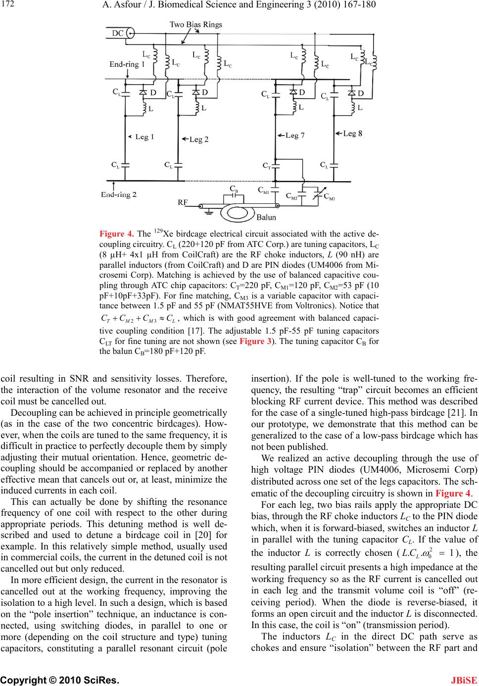 A. Asfour / J. Biomedical Science and Engineering 3 (2010) 167-180 Copyright © 2010 SciRes. 172 JBiSE Figure 4. The 129Xe birdcage electrical circuit associated with the active de- coupling circuitry. CL (220+120 pF from ATC Corp.) are tuning capacitors, LC (8 µH+ 4x1 µH from CoilCraft) are the RF choke inductors, L (90 nH) are parallel inductors (from CoilCraft) and D are PIN diodes (UM4006 from Mi- crosemi Corp). Matching is achieved by the use of balanced capacitive cou- pling through ATC chip capacitors: CT=220 pF, CM1=120 pF, CM2=53 pF (10 pF+10pF+33pF). For fine matching, CM3 is a variable capacitor with capaci- tance between 1.5 pF and 55 pF (NMAT55HVE from Voltronics). Notice that , which is with good agreement with balanced capaci- tive coupling condition [17]. The adjustable 1.5 pF-55 pF tuning capacitors CLT for fine tuning are not shown (see Figure 3). The tuning capacitor CB for the balun CB=180 pF+120 pF. 23TM M CC CC L coil resulting in SNR and sensitivity losses. Therefore, the interaction of the volume resonator and the receive coil must be cancelled out. Decoupling can be achieved in principle geometrically (as in the case of the two concentric birdcages). How- ever, when the coils are tuned to the same frequency, it is difficult in practice to perfectly decouple them by simply adjusting their mutual orientation. Hence, geometric de- coupling should be accompanied or replaced by another effective mean that cancels out or, at least, minimize the induced currents in each coil. This can actually be done by shifting the resonance frequency of one coil with respect to the other during appropriate periods. This detuning method is well de- scribed and used to detune a birdcage coil in [20] for example. In this relatively simple method, usually used in commercial coils, the current in the detuned coil is not cancelled out but only reduced. In more efficient design, the current in the resonator is cancelled out at the working frequency, improving the isolation to a high level. In such a design, which is based on the “pole insertion” technique, an inductance is con- nected, using switching diodes, in parallel to one or more (depending on the coil structure and type) tuning capacitors, constituting a parallel resonant circuit (pole insertion). If the pole is well-tuned to the working fre- quency, the resulting “trap” circuit becomes an efficient blocking RF current device. This method was described for the case of a single-tuned high-pass birdcage [21]. In our prototype, we demonstrate that this method can be generalized to the case of a low-pass birdcage which has not been published. We realized an active decoupling through the use of high voltage PIN diodes (UM4006, Microsemi Corp) distributed across one set of the legs capacitors. The sch- ematic of the decoupling circuitry is shown in Figure 4. For each leg, two bias rails apply the appropriate DC bias, through the RF choke inductors LC to the PIN diode which, when it is forward-biased, switches an inductor L in parallel with the tuning capacitor CL. If the value of the inductor L is correctly chosen (2 0 .. 1 L LC ), the resulting parallel circuit presents a high impedance at the working frequency so as the RF current is cancelled out in each leg and the transmit volume coil is “off” (re- ceiving period). When the diode is reverse-biased, it forms an open circuit and the inductor L is disconnected. In this case, the coil is “on” (transmission period). The inductors LC in the direct DC path serve as chokes and ensure “isolation” between the RF part and 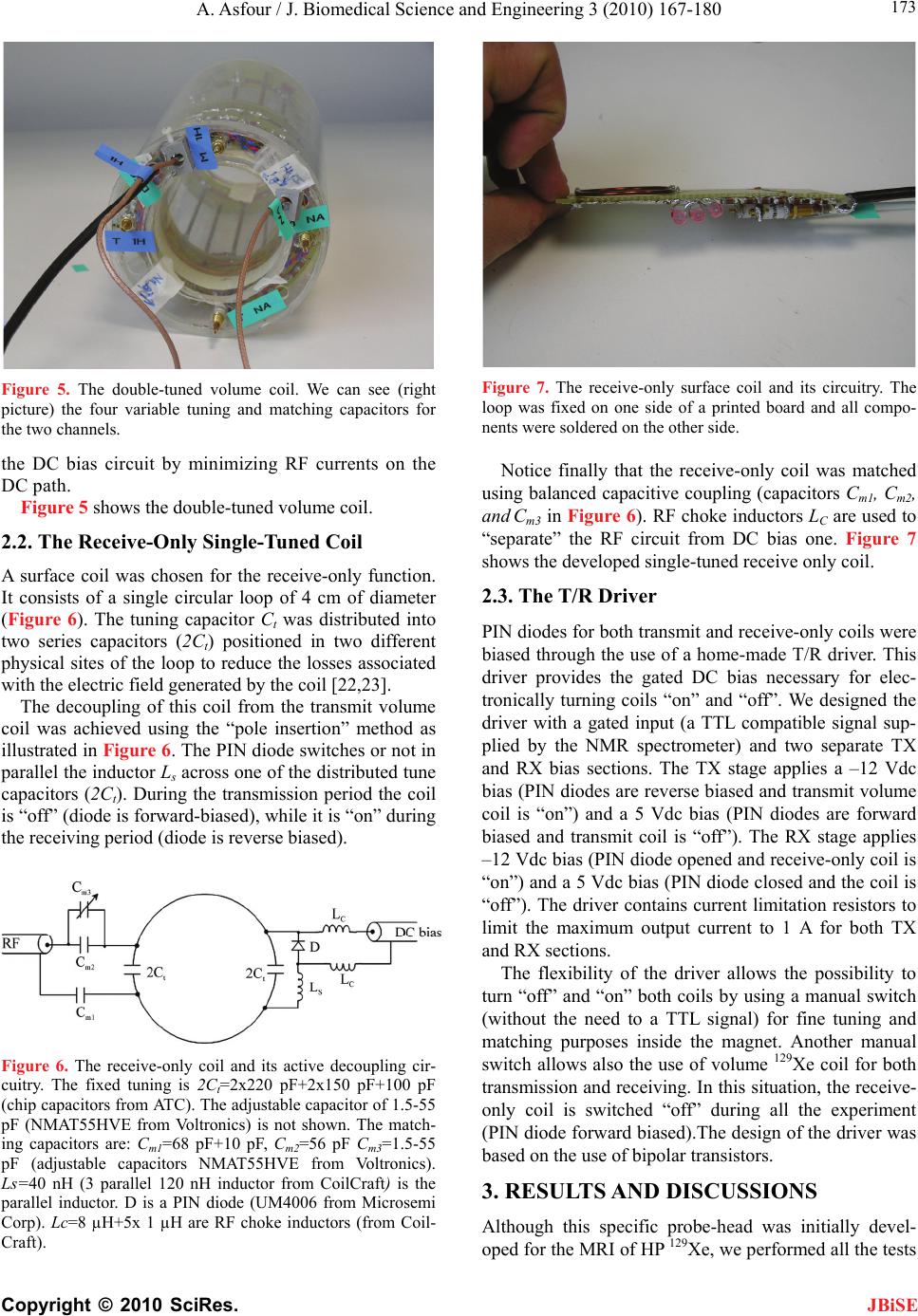 A. Asfour / J. Biomedical Science and Engineering 3 (2010) 167-180 Copyright © 2010 SciRes. 173 JBiSE Figure 5. The double-tuned volume coil. We can see (right picture) the four variable tuning and matching capacitors for the two channels. the DC bias circuit by minimizing RF currents on the DC path. Figure 5 shows the double-tuned volume coil. 2.2. The Receive-Only Single-Tuned Coil A surface coil was chosen for the receive-only function. It consists of a single circular loop of 4 cm of diameter (Figure 6). The tuning capacitor Ct was distributed into two series capacitors (2Ct) positioned in two different physical sites of the loop to reduce the losses associated with the electric field generated by the coil [22,23]. The decoupling of this coil from the transmit volume coil was achieved using the “pole insertion” method as illustrated in Figure 6. The PIN diode switches or not in parallel the inductor Ls across one of the distributed tune capacitors (2Ct). During the transmission period the coil is “off” (diode is forward-biased), while it is “on” during the receiving period (diode is reverse biased). Figure 6. The receive-only coil and its active decoupling cir- cuitry. The fixed tuning is 2Ct=2x220 pF+2x150 pF+100 pF (chip capacitors from ATC). The adjustable capacitor of 1.5-55 pF (NMAT55HVE from Voltronics) is not shown. The match- ing capacitors are: Cm1=68 pF+10 pF, Cm2=56 pF Cm3=1.5-55 pF (adjustable capacitors NMAT55HVE from Voltronics). Ls=40 nH (3 parallel 120 nH inductor from CoilCraft) is the parallel inductor. D is a PIN diode (UM4006 from Microsemi Corp). Lc=8 µH+5x 1 µH are RF choke inductors (from Coil- Craft). Figure 7. The receive-only surface coil and its circuitry. The loop was fixed on one side of a printed board and all compo- nents were soldered on the other side. Notice finally that the receive-only coil was matched using balanced capacitive coupling (capacitors Cm1, Cm2, and Cm3 in Figure 6). RF choke inductors LC are used to “separate” the RF circuit from DC bias one. Figure 7 shows the developed single-tuned receive only coil. 2.3. The T/R Driver PIN diodes for both transmit and receive-only coils were biased through the use of a home-made T/R driver. This driver provides the gated DC bias necessary for elec- tronically turning coils “on” and “off”. We designed the driver with a gated input (a TTL compatible signal sup- plied by the NMR spectrometer) and two separate TX and RX bias sections. The TX stage applies a –12 Vdc bias (PIN diodes are reverse biased and transmit volume coil is “on”) and a 5 Vdc bias (PIN diodes are forward biased and transmit coil is “off”). The RX stage applies –12 Vdc bias (PIN diode opened and receive-only coil is “on”) and a 5 Vdc bias (PIN diode closed and the coil is “off”). The driver contains current limitation resistors to limit the maximum output current to 1 A for both TX and RX sections. The flexibility of the driver allows the possibility to turn “off” and “on” both coils by using a manual switch (without the need to a TTL signal) for fine tuning and matching purposes inside the magnet. Another manual switch allows also the use of volume 129Xe coil for both transmission and receiving. In this situation, the receive- only coil is switched “off” during all the experiment (PIN diode forward biased).The design of the driver was based on the use of bipolar transistors. 3. RESULTS AND DISCUSSIONS Although this specific probe-head was initially devel- oped for the MRI of HP 129Xe, we performed all the tests 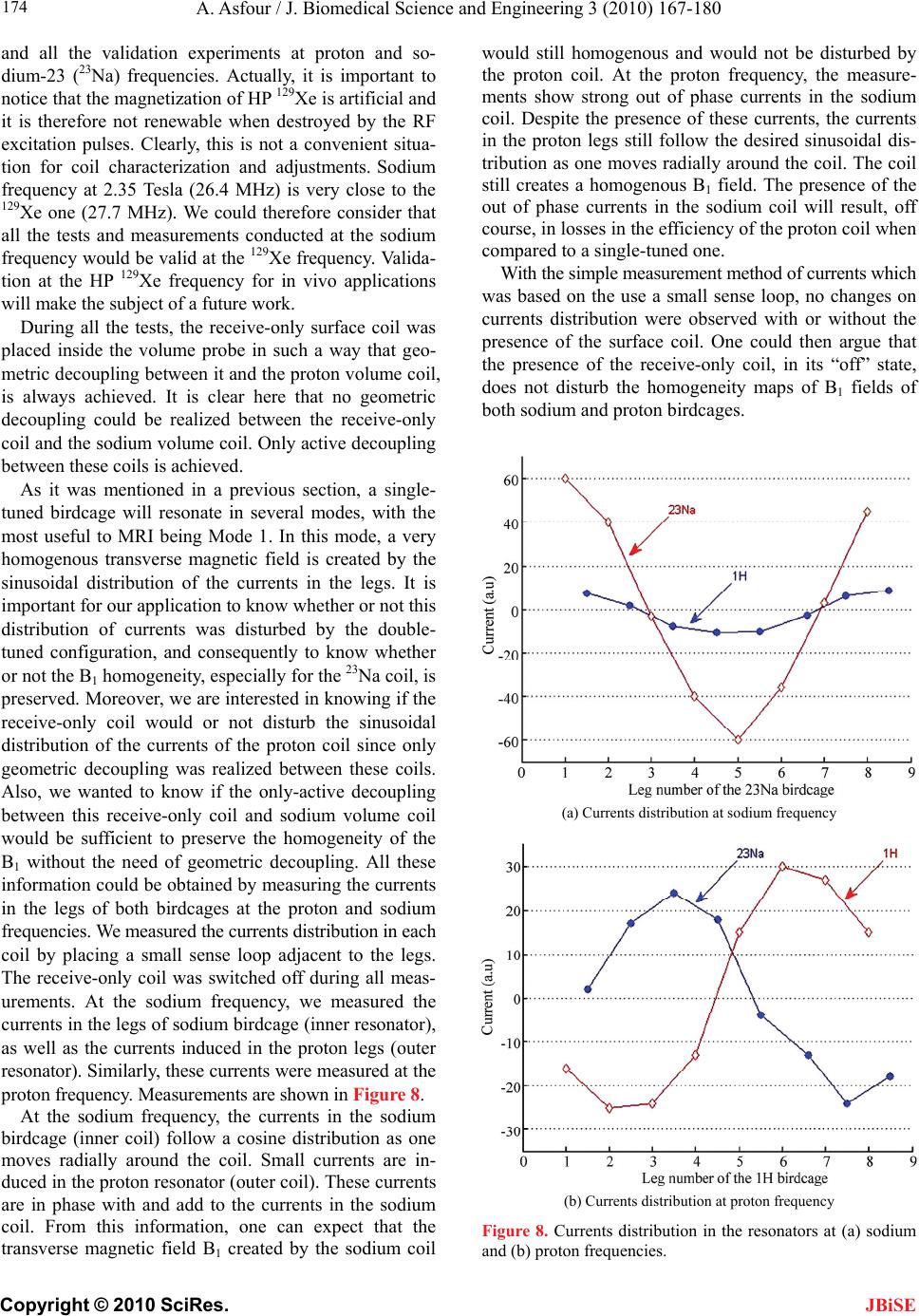 A. Asfour / J. Biomedical Science and Engineering 3 (2010) 167-180 Copyright © 2010 SciRes. 174 JBiSE and all the validation experiments at proton and so- dium-23 (23Na) frequencies. Actually, it is important to notice that the magnetization of HP 129Xe is artificial and it is therefore not renewable when destroyed by the RF excitation pulses. Clearly, this is not a convenient situa- tion for coil characterization and adjustments. Sodium frequency at 2.35 Tesla (26.4 MHz) is very close to the 129Xe one (27.7 MHz). We could therefore consider that all the tests and measurements conducted at the sodium frequency would be valid at the 129Xe frequency. Valida- tion at the HP 129Xe frequency for in vivo applications will make the subject of a future work. During all the tests, the receive-only surface coil was placed inside the volume probe in such a way that geo- metric decoupling between it and the proton volume coil, is always achieved. It is clear here that no geometric decoupling could be realized between the receive-only coil and the sodium volume coil. Only active decoupling between these coils is achieved. As it was mentioned in a previous section, a single- tuned birdcage will resonate in several modes, with the most useful to MRI being Mode 1. In this mode, a very homogenous transverse magnetic field is created by the sinusoidal distribution of the currents in the legs. It is important for our application to know whether or not this distribution of currents was disturbed by the double- tuned configuration, and consequently to know whether or not the B1 homogeneity, especially for the 23Na coil, is preserved. Moreover, we are interested in knowing if the receive-only coil would or not disturb the sinusoidal distribution of the currents of the proton coil since only geometric decoupling was realized between these coils. Also, we wanted to know if the only-active decoupling between this receive-only coil and sodium volume coil would be sufficient to preserve the homogeneity of the B1 without the need of geometric decoupling. All these information could be obtained by measuring the currents in the legs of both birdcages at the proton and sodium frequencies. We measured the currents distribution in each coil by placing a small sense loop adjacent to the legs. The receive-only coil was switched off during all meas- urements. At the sodium frequency, we measured the currents in the legs of sodium birdcage (inner resonator), as well as the currents induced in the proton legs (outer resonator). Similarly, these currents were measured at the proton frequency. Measurements are shown in Figure 8. At the sodium frequency, the currents in the sodium birdcage (inner coil) follow a cosine distribution as one moves radially around the coil. Small currents are in- duced in the proton resonator (outer coil). These currents are in phase with and add to the currents in the sodium coil. From this information, one can expect that the transverse magnetic field B1 created by the sodium coil would still homogenous and would not be disturbed by the proton coil. At the proton frequency, the measure- ments show strong out of phase currents in the sodium coil. Despite the presence of these currents, the currents in the proton legs still follow the desired sinusoidal dis- tribution as one moves radially around the coil. The coil still creates a homogenous B1 field. The presence of the out of phase currents in the sodium coil will result, off course, in losses in the efficiency of the proton coil when compared to a single-tuned one. With the simple measurement method of currents which was based on the use a small sense loop, no changes on currents distribution were observed with or without the presence of the surface coil. One could then argue that the presence of the receive-only coil, in its “off” state, does not disturb the homogeneity maps of B1 fields of both sodium and proton birdcages. (a) Currents distribution at sodium frequency (b) Currents distribution at proton frequency Figure 8. Currents distribution in the resonators at (a) sodium and (b) proton frequencies. 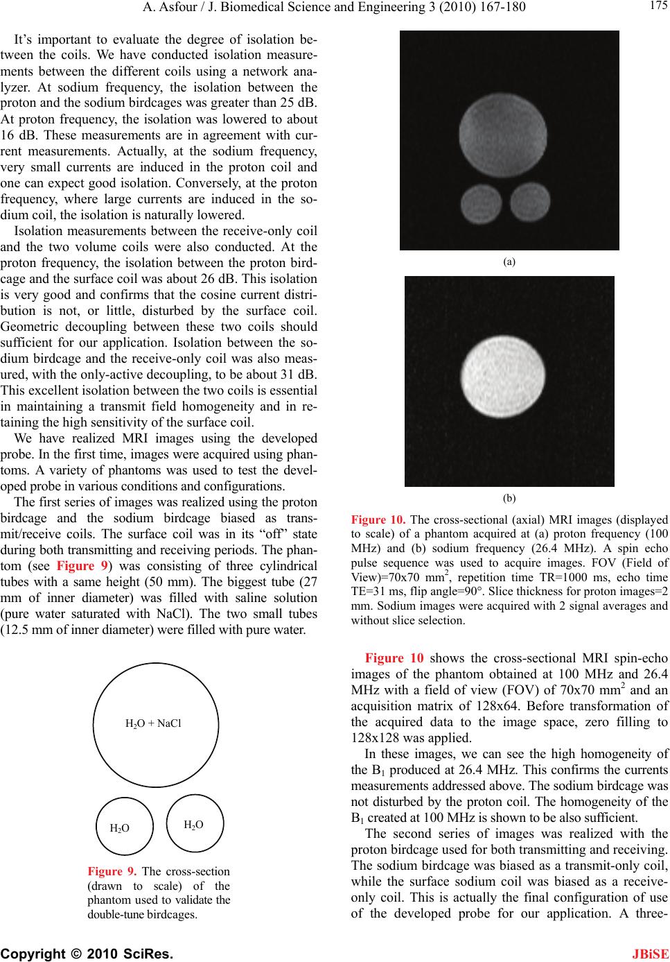 A. Asfour / J. Biomedical Science and Engineering 3 (2010) 167-180 Copyright © 2010 SciRes. 175 JBiSE It’s important to evaluate the degree of isolation be- tween the coils. We have conducted isolation measure- ments between the different coils using a network ana- lyzer. At sodium frequency, the isolation between the proton and the sodium birdcages was greater than 25 dB. At proton frequency, the isolation was lowered to about 16 dB. These measurements are in agreement with cur- rent measurements. Actually, at the sodium frequency, very small currents are induced in the proton coil and one can expect good isolation. Conversely, at the proton frequency, where large currents are induced in the so- dium coil, the isolation is naturally lowered. Isolation measurements between the receive-only coil and the two volume coils were also conducted. At the proton frequency, the isolation between the proton bird- cage and the surface coil was about 26 dB. This isolation is very good and confirms that the cosine current distri- bution is not, or little, disturbed by the surface coil. Geometric decoupling between these two coils should sufficient for our application. Isolation between the so- dium birdcage and the receive-only coil was also meas- ured, with the only-active decoupling, to be about 31 dB. This excellent isolation between the two coils is essential in maintaining a transmit field homogeneity and in re- taining the high sensitivity of the surface coil. We have realized MRI images using the developed probe. In the first time, images were acquired using phan- toms. A variety of phantoms was used to test the devel- oped probe in various conditions and configurations. The first series of images was realized using the proton birdcage and the sodium birdcage biased as trans- mit/receive coils. The surface coil was in its “off” state during both transmitting and receiving periods. The phan- tom (see Figure 9) was consisting of three cylindrical tubes with a same height (50 mm). The biggest tube (27 mm of inner diameter) was filled with saline solution (pure water saturated with NaCl). The two small tubes (12.5 mm of inner diameter) were filled with pure water. H 2 O + NaCl H 2 O H 2 O Figure 9. The cross-section (drawn to scale) of the phantom used to validate the double-tune birdcages. (a) (b) Figure 10. The cross-sectional (axial) MRI images (displayed to scale) of a phantom acquired at (a) proton frequency (100 MHz) and (b) sodium frequency (26.4 MHz). A spin echo pulse sequence was used to acquire images. FOV (Field of View)=70x70 mm2, repetition time TR=1000 ms, echo time TE=31 ms, flip angle=90°. Slice thickness for proton images=2 mm. Sodium images were acquired with 2 signal averages and without slice selection. Figure 10 shows the cross-sectional MRI spin-echo images of the phantom obtained at 100 MHz and 26.4 MHz with a field of view (FOV) of 70x70 mm2 and an acquisition matrix of 128x64. Before transformation of the acquired data to the image space, zero filling to 128x128 was applied. In these images, we can see the high homogeneity of the B1 produced at 26.4 MHz. This confirms the currents measurements addressed above. The sodium birdcage was not disturbed by the proton coil. The homogeneity of the B1 created at 100 MHz is shown to be also sufficient. The second series of images was realized with the proton birdcage used for both transmitting and receiving. The sodium birdcage was biased as a transmit-only coil, while the surface sodium coil was biased as a receive- only coil. This is actually the final configuration of use of the developed probe for our application. A three- 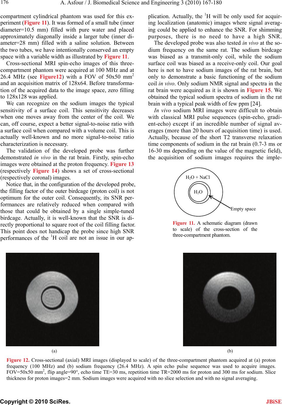 A. Asfour / J. Biomedical Science and Engineering 3 (2010) 167-180 Copyright © 2010 SciRes. 176 compartment cylindrical phantom was used for this ex- periment (Figure 11). It was formed of a small tube (inner diameter=10.5 mm) filled with pure water and placed approximately diagonally inside a larger tube (inner di- ameter=28 mm) filled with a saline solution. Between the two tubes, we have intentionally conserved an empty space with a variable width as illustrated by Figure 11. JBiSE Cross-sectional MRI spin-echo images of this three- compartment phantom were acquired at 100 MHz and at 26.4 MHz (see Figure12) with a FOV of 50x50 mm2 and an acquisition matrix of 128x64. Before transforma- tion of the acquired data to the image space, zero filling to 128x128 was applied. We can recognize on the sodium images the typical sensitivity of a surface coil. This sensitivity decreases when one moves away from the center of the coil. We can, off course, expect a better signal-to-noise ratio with a surface coil when compared with a volume coil. This is actually well-known and no more signal-to-noise ratio characterization is necessary. The validation of the developed probe was further demonstrated in vivo in the rat brain. Firstly, spin-echo images were obtained at the proton frequency. Figure 13 (respectively Figure 14) shows a set of cross-sectional (respectively coronal) images. Notice that, in the configuration of the developed probe, the filling factor of the outer birdcage (proton coil) is not optimum for the outer coil. Consequently, its SNR per- formances are relatively reduced when compared with those that could be obtained by a single simple-tuned birdcage. Actually, it is well-known that the SNR is di- rectly proportional to square root of the coil filling factor. This point does not handicap the probe since high SNR performances of the 1H coil are not an issue in our ap- plication. Actually, the 1H will be only used for acquir- ing localization (anatomic) images where signal averag- ing could be applied to enhance the SNR. For shimming purposes, there is no need to have a high SNR. The developed probe was also tested in vivo at the so- dium frequency on the same rat. The sodium birdcage was biased as a transmit-only coil, while the sodium surface coil was biased as a receive-only coil. Our goal here is not to have sodium images of the rat brain, but only to demonstrate a basic functioning of the sodium coil in vivo. Only sodium NMR signal and spectra in the rat brain were acquired as it is shown in Figure 15. We obtained the typical sodium spectra of sodium in the rat brain with a typical peak width of few ppm [24]. In vivo sodium MRI images were difficult to obtain with classical MRI pulse sequences (spin-echo, gradi- ent-echo) except if an incredible number of signal av- erages (more than 20 hours of acquisition time) is used. Actually, because of the short T2 transverse relaxation time components of sodium in the rat brain (0.7-3 ms or 16-30 ms depending on the value of the magnetic field), the acquisition of sodium images requires the imple- H 2 O + NaCl H 2 O Empty space Figure 11. A schematic diagram (drawn to scale) of the cross-section of the three-compartment phantom. (a) (b) Figure 12. Cross-sectional (axial) MRI images (displayed to scale) of the three-compartment phantom acquired at (a) proton frequency (100 MHz) and (b) sodium frequency (26.4 MHz). A spin echo pulse sequence was used to acquire images. FOV=50x50 mm2, flip angle=90°, echo time TE=30 ms, repetition time TR=2000 ms for proton and 300 ms for sodium. Slice thickness for proton images=2 mm. Sodium images were acquired with no slice selection and with no signal averaging. 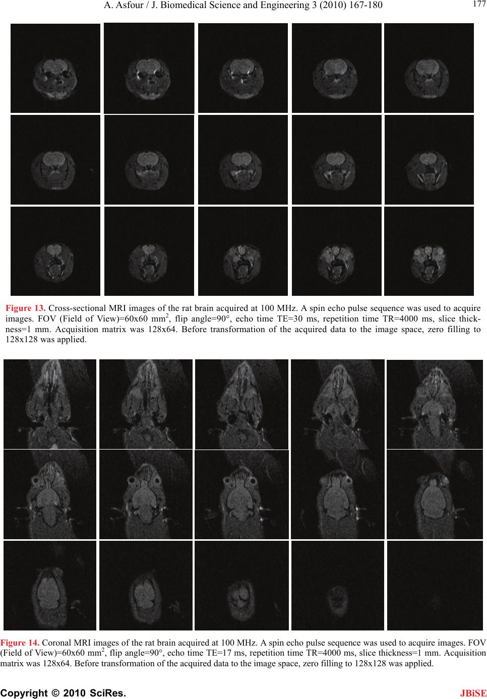 A. Asfour / J. Biomedical Science and Engineering 3 (2010) 167-180 Copyright © 2010 SciRes. 177 Figure 13. Cross-sectional MRI images of the rat brain acquired at 100 MHz. A spin echo pulse sequence was used to acquire images. FOV (Field of View)=60x60 mm2, flip angle=90°, echo time TE=30 ms, repetition time TR=4000 ms, slice thick- ness=1 mm. Acquisition matrix was 128x64. Before transformation of the acquired data to the image space, zero filling to 128x128 was applied. Figure 14. Coronal MRI images of the rat brain acquired at 100 MHz. A spin echo pulse sequence was used to acquire images. FOV (Field of View)=60x60 mm2, flip angle=90°, echo time TE=17 ms, repetition time TR=4000 ms, slice thickness=1 mm. Acquisition matrix was 128x64. Before transformation of the acquired data to the image space, zero filling to 128x128 was applied. JBiSE 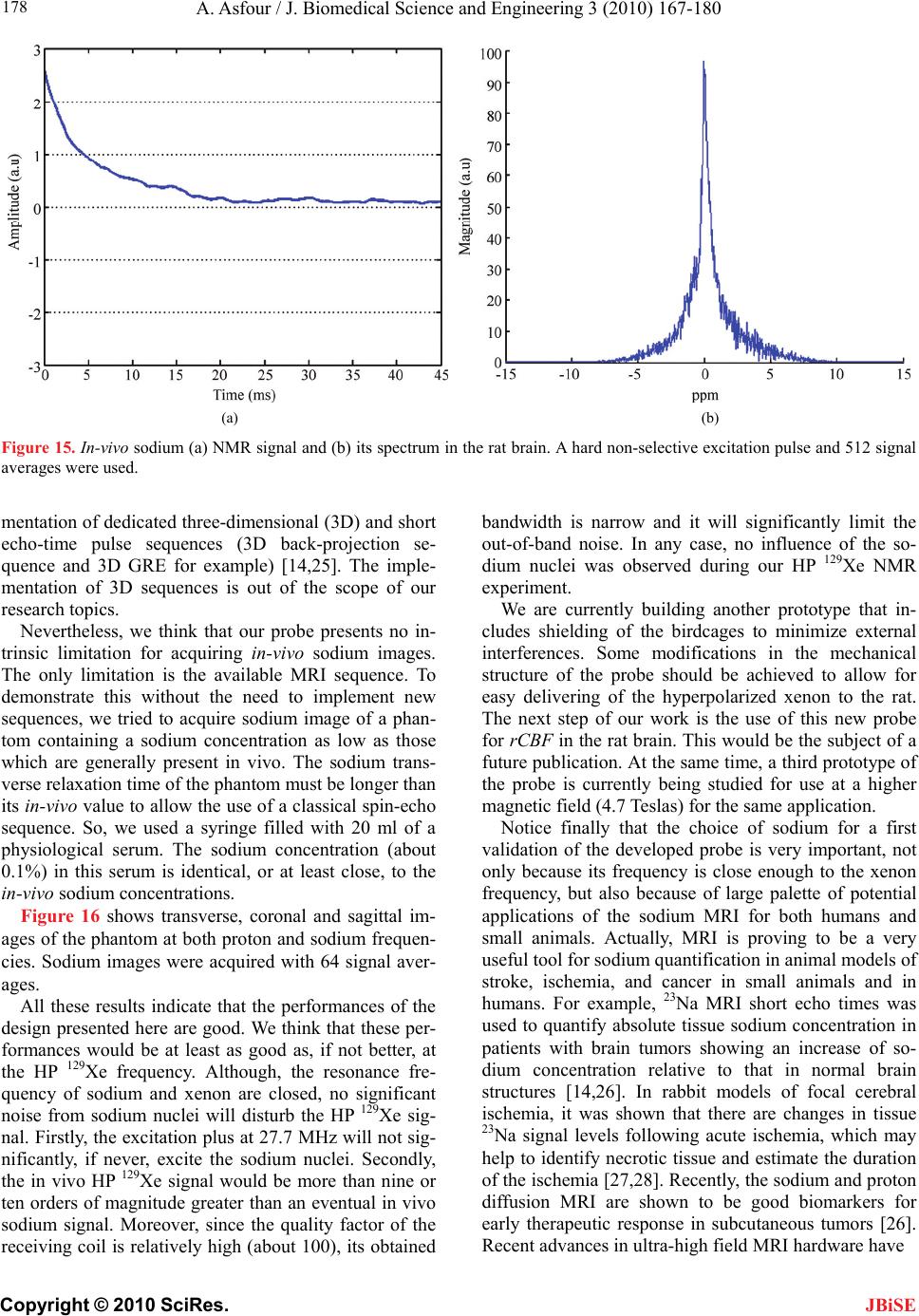 A. Asfour / J. Biomedical Science and Engineering 3 (2010) 167-180 Copyright © 2010 SciRes. 178 (a) (b) Figure 15. In-vivo sodium (a) NMR signal and (b) its spectrum in the rat brain. A hard non-selective excitation pulse and 512 signal averages were used. mentation of dedicated three-dimensional (3D) and short echo-time pulse sequences (3D back-projection se- quence and 3D GRE for example) [14,25]. The imple- mentation of 3D sequences is out of the scope of our research topics. JBiSE Nevertheless, we think that our probe presents no in- trinsic limitation for acquiring in-vivo sodium images. The only limitation is the available MRI sequence. To demonstrate this without the need to implement new sequences, we tried to acquire sodium image of a phan- tom containing a sodium concentration as low as those which are generally present in vivo. The sodium trans- verse relaxation time of the phantom must be longer than its in-vivo value to allow the use of a classical spin-echo sequence. So, we used a syringe filled with 20 ml of a physiological serum. The sodium concentration (about 0.1%) in this serum is identical, or at least close, to the in-vivo sodium concentrations. Figure 16 shows transverse, coronal and sagittal im- ages of the phantom at both proton and sodium frequen- cies. Sodium images were acquired with 64 signal aver- ages. All these results indicate that the performances of the design presented here are good. We think that these per- formances would be at least as good as, if not better, at the HP 129Xe frequency. Although, the resonance fre- quency of sodium and xenon are closed, no significant noise from sodium nuclei will disturb the HP 129Xe sig- nal. Firstly, the excitation plus at 27.7 MHz will not sig- nificantly, if never, excite the sodium nuclei. Secondly, the in vivo HP 129Xe signal would be more than nine or ten orders of magnitude greater than an eventual in vivo sodium signal. Moreover, since the quality factor of the receiving coil is relatively high (about 100), its obtained bandwidth is narrow and it will significantly limit the out-of-band noise. In any case, no influence of the so- dium nuclei was observed during our HP 129Xe NMR experiment. We are currently building another prototype that in- cludes shielding of the birdcages to minimize external interferences. Some modifications in the mechanical structure of the probe should be achieved to allow for easy delivering of the hyperpolarized xenon to the rat. The next step of our work is the use of this new probe for rCBF in the rat brain. This would be the subject of a future publication. At the same time, a third prototype of the probe is currently being studied for use at a higher magnetic field (4.7 Teslas) for the same application. Notice finally that the choice of sodium for a first validation of the developed probe is very important, not only because its frequency is close enough to the xenon frequency, but also because of large palette of potential applications of the sodium MRI for both humans and small animals. Actually, MRI is proving to be a very useful tool for sodium quantification in animal models of stroke, ischemia, and cancer in small animals and in humans. For example, 23Na MRI short echo times was used to quantify absolute tissue sodium concentration in patients with brain tumors showing an increase of so- dium concentration relative to that in normal brain structures [14,26]. In rabbit models of focal cerebral ischemia, it was shown that there are changes in tissue 23Na signal levels following acute ischemia, which may help to identify necrotic tissue and estimate the duration of the ischemia [27,28]. Recently, the sodium and proton diffusion MRI are shown to be good biomarkers for early therapeutic response in subcutaneous tumors [26]. Recent advances in ultra-high field MRI hardware have 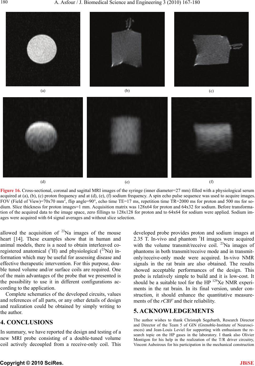 A. Asfour / J. Biomedical Science and Engineering 3 (2010) 167-180 Copyright © 2010 SciRes. 180 JBiSE (a) (b) (c) (d) (e) (f) Figure 16. Cross-sectional, coronal and sagittal MRI images of the syringe (inner diameter=27 mm) filled with a physiological serum acquired at (a), (b), (c) proton frequency and at (d), (e), (f) sodium frequency. A spin echo pulse sequence was used to acquire images. FOV (Field of View)=70x70 mm2, flip angle=90°, echo time TE=17 ms, repetition time TR=2000 ms for proton and 500 ms for so- dium. Slice thickness for proton images=1 mm. Acquisition matrix was 128x64 for proton and 64x32 for sodium. Before transforma- tion of the acquired data to the image space, zero fillings to 128x128 for proton and to 64x64 for sodium were applied. Sodium im- ages were acquired with 64 signal averages and without slice selection. allowed the acquisition of 23Na images of the mouse heart [14]. These examples show that in human and animal models, there is a need to obtain interleaved co- registered anatomical (1H) and physiological (23Na) in- formation which may be useful for assessing disease and effective therapeutic intervention. For this purpose, dou- ble tuned volume and/or surface coils are required. One of the main advantages of the probe that we presented is the possibility to use it in different configurations ac- cording to the application. Complete schematics of the developed circuits, values and references of all parts, or any other details of design and realization could be obtained by simply writing to the author. 4. CONCLUSIONS In summary, we have reported the design and testing of a new MRI probe consisting of a double-tuned volume coil actively decoupled from a receive-only coil. This developed probe provides proton and sodium images at 2.35 T. In-vivo and phantom 1H images were acquired with the volume transmit/receive coil. 23Na images of phantoms in both transmit/receive mode and in transmit- only/receive-only mode were acquired. In-vivo NMR signals in the rat brain are also obtained. The results showed acceptable performances of the design. This probe is relatively simple to build and it is low-cost. It should be a suitable tool for the HP 129Xe NMR experi- ments in the rat brain. In its final version, under con- struction, it should enhance the quantitative measure- ments of the rCBF and their reliability. 5. ACKNOWLEDGEMENTS The author wishes to thank Christoph Segebarth, Research Director and Director of the Team 5 of GIN (Grenoble-Institute of Neurosci- ences) and Jean-Louis Leviel for supporting with enthusiasm the re- search topic on the HP gases in the laboratory. I thank also Olivier Montigon for his help in the realization of the T/R driver circuitry, Vincent Auboiroux for his participation in the mechanical construction  A. Asfour / J. Biomedical Science and Engineering 3 (2010) 167-180 Copyright © 2010 SciRes. 180 JBiSE of the probe. Finally, I am very thankful to Emmanuel Barbier for his support in using his developed MRI sequences and visualization soft- ware and for helpful discussions. All these persons are working at the Team 5 of GIN. REFERENCES [1] Albert, M.S. et al. (1994) Biological magnetic resonance imaging using laser polarized 129Xe. Nature, 370, 199-201. [2] Kilian, W. et al. (2004) Dynamic NMR spectroscopy of hyperpolarized 12 9Xe in human brain analyzed by an up- take model. Magnetic Resonance in Medicine (MRM), 51, 843-847. [3] Venkatesh, A.K. et al. (2001) Using dynamic hyperpo- larized xenon MR to measure brain perfusion. Proceed- ing of the International Society of Magnetic Resonance in Medicine, 9, 951. [4] Swanson, S.D. et al. (1997) Brain MRI with la- ser-polarized 129Xe. Magnetic Resonance in Medicine (MRM), 38, 695-698. [5] Duhamel, G. et al. (2002) Global and regional cerebral blood flow measurements using NMR of injected hyper- polarized xenon-129. Acad Radiol., 9(2), 498-500. [6] Asfour, A. et al. (2006) Development of a fully digital and low frequency NMR system for polarization meas- urement of hyperpolarized gases. Proceedings of the IEEE Instrumentation and Measurement Technology Conference IMTC, Sorrento, Italy. [7] Asfour, A. (2008) A new DAQ-based and versatile low-cost NMR spectrometer working at very-low mag- netic field (4.5 mT): A palette of potential applications. Proceedings of the IEEE International Instrumentation and Measurement Technology Conference I2MTC, Van- couver, Canada. [8] Ackerman, et al. (1980) Mapping of metabolites in whole animals by 31P NMR using surface coils. Nature, 283, 167-170. [9] Hayes, C.E. et al. (1985) An efficient, highly homoge- nous radiofrequency coil for whole-body NMR imaging at 1.5 T. Journal of Magnetic Resonance, 63, 622-628. [10] Fitzsimmons, J.R. et al. (1993) Double Resonant quad- rature birdcage. Magnetic Resonance in Medicine (MRM), 30, 107-114. [11] Rath, A.R. (1990) Design and performance of a dou- ble-tuned birdcage coil. Journal of Magnetic Resonance, 86, 488-495. [12] Shen, G.X. et al. (1997) Dual-frequency, dual-quadrature, birdcage RF coil design with identical B1 pattern for so- dium and proton imaging of the human brain at 1.5 T. Magnetic Resonance in Medicine, 38, 717-725. [13] Lanz, T. et al. (2001) Double tuned 23Na 1H nuclear magnetic resonance birdcage for application on mice in vivo. Review of Scientific Instruments, 72(5), 2508-2510. [14] Alecci, M. et al. (2006) Practical design of a 4 Tesla double-tuned RF surface coil for interleaved 1H and 23Na MRI of the rat brain. Journal of Magnetic Resonance, 181, 203-211. [15] Leach, M.O. et al. (1986) The design and use of a dual-frequency surface coil providing proton images for improved localization in 31P spectroscopy of small le- sions. Med Phys, 13, 510-513. [16] Volotovskyy, V. et al. (2002) Doubly tunable double ring surface coil. Concepts in Magnetic Resonance, B(17B), 11-16. [17] Mispelter, J., Lupu, M. and Briguet, A. (2006) NMR Probeheads for Biophysical and Biomedical Experiments: Theoretical Principles and Practical Guidelines, Impe- rial College Press. [18] Chin, C.L. et al. (2002) BirdcageBuilder: Design of specified-geometry birdcage coils with desired current pattern and resonance frequency. Concepts in Magnetic Resonance, 15(2), 156-163. [19] The ARRL Handbook for Radio Amateurs, Published by the American Radio Relay League, 1996. [20] Streif, J.U.G. et al. (2003) A coil combination for mag- netic resonance perfusion imaging of mice in vivo at 7 T. Review of Scientific Instruments, 74(5), 2843-2848. [21] Barberi, E.A. et al. (2000) A transmit-only/receive-only (TORO) RF system for high-field MRI/MRS applications. Magnetic Resonance in Medicine (MRM), 43, 284-289. [22] Décorps, M. et al. (1985) An inductively coupled, series tuned NMR probe. Journal of Magnetic Resonance, 65, 100-109. [23] Hoult, D.I. and Lauterburg, P.C. (1979) The sensitivity of the zeugmatographic experiment involving human sam- ples. Journal of Magnetic Resonance, 34, 425-433. [24] Naritomi, H. et al. (1987) In vivo measurements of the intra- and extra-cellular +Na and water in the brain and muscle by nuclear magnetic resonance spectroscopy with shift reagent. BIOPHYS Journal, Biophysical Society, 52, 611-616. [25] Schepkin, V.D. et al. (2006) Sodium and proton diffusion MRI as biomarkers for early therapeutic response in subcutaneous tumors. Magnetic Resonance Imaging, 24, 273-278. [26] Ouwerkerk, R. et al. (2003) Tissue sodium concentration in human brain tumors as measured with 23Na MR imag- ing. Radiology, 227, 529-537. [27] Bartha, R. et al. (2004) Sodium T2*-weighted MR im- aging of acute focal cerebral ischemia in rabbits. Mag- netic Resonance Imaging, 22, 983-991. [28] Wang, Y. et al. (2000) Brain tissue sodium is a ticking clock telling time after arterial occlusion in rat focal cerebral ischemia. Stroke, 31, 1386-1391.
|