 J. Biomedical Science and Engineering, 2010, 3, 124-137 doi:10.4236/jbise.2010.32018 Published Online February 2010 (http://www.SciRP.org/journal/jbise/ JBiSE ). Published Online February 2010 in SciRes. http://www.scirp.org/journal/jbise Effect of deformation rate on the mechanical properties of arteries Jorge O. Virues Delgadillo1, Sebastien Delorme2, Vincent Mora2, Robert DiRaddo2, Savvas G. Hatzikiriakos1 1Department of Chemical & Biological Engineering, UBC, Vancouver, BC, Canada 2Industrial Materials Institute, National Research Council of Canada, Boucherville, QC, Canada Email: hatzikir@interchange.ubc.ca; Sebastien.Delorme@imi.cnrc-nrc.gc.ca Received 27 June 2008; revised 18 December 2009; accepted 20 December 2009. ABSTRACT Pig aorta samples were tested uniaxially and equi- biaxially at deformation rates from 10 to 200 %/s. Under uniaxial and biaxial testing, loading forces were reduced up to 20% when the deformation rate was increased from 10 to 200 %/s, which is the opp- osite to the behaviour seen in other biological tissues. A rate-dependent isotropic hyperelastic constitutive equation, derived from the Mooney-Rivlin model, was fitted to the experimental results (e.g. aorta specimens) using an inverse finite element technique. In the proposed model, one of the material par- ameters is a linear function of the deformation rate. The inverse relationship between stiffness and defo- rmation rate raises doubts on the hypothesized rel- ationship between intramural stress, arterial injury, and restenosis. Keywords: Mechanical Properties; Artery; Uniaxial & Biaxial Testing; Deformation Rate; Viscoelasticity; Constitutive Model 1. INTRODUCTION The knowledge of the viscoelastic properties is impor- tant to predict the biomechanical behaviour of soft tis- sues. To model their viscoelastic behaviour, first one performs appropriate mechanical tests to characterize de- formation-rate effects, and then one selects a constitutive equation capable of representing those effects. Material parameter estimation is fundamental for posterior simu- lation of soft tissue at boundary conditions not selected in the experimental protocol. The effect of deformation rate on the mechanical properties of soft biological tissues has been investigated, in particular for ligaments [1-7], tendons [4,7-9], spines [10-13], bones [14-17], liver [18], heart valves [19,20] and myocardium [21,22]. Most biological tissues stiffen with increasing deformation rate [4,7,9,11-13, 17]. This time-dependent behavior has been described by viscoe- lastic constitutive models [6,22-26]. However, it was recently demonstrated that some biological tissues, such as liver, myocardium and skin, soften with increasing deformation rate [18,22]. Deformation rate effects of arteries, in particular thoracic aorta, were not included in previous studies. Overstretch injury to the arterial wall during an an- gioplasty or stenting procedure has been shown to be correlated to the incidence of restenosis, i.e. in-growing tissue re-blocking the artery lumen [26,27]. Based on the hypothesis that lower deformation rate results in lower intramural stresses, slow balloon inflation has been pro- posed as a means to minimize vascular injury and reduce restenosis incidence [28]. Early studies did not conclude there was any difference in restenosis rates between conventional and slow balloon inflation [28-30], while some observed better immediate results [31,32]. In more recent studies, significantly lower restenosis rates were clinically observed with slow balloon inflation [33,34]. Slow stent deployment has also been proposed as a means to minimize arterial injury [35]. Finite element simulation of angioplasty and stenting can be used to optimize angioplasty procedure parame- ters, such as inflation pressure [36-40]. Optimization of inflation pressure rate requires accurate constitutive mo- deling of artery behavior including the effect of defor- mation rate. Numerous experimental studies have been performed to characterize the mechanical behaviour of arteries in vitro [41-44]. However, only a single defor- mation rate was used. The objective of this study is thus to measure and model the effect of deformation rate on the tensile be- havior of the arteries (e.g. pig aortas). In other words, the intention of this paper is to investigate experimentally the dependence of uniaxial and biaxial extensional str- etching of arterial wall on the deformation-rate, and consequently to modeling the experimental data by me- ans of an appropriate constitutive equation. 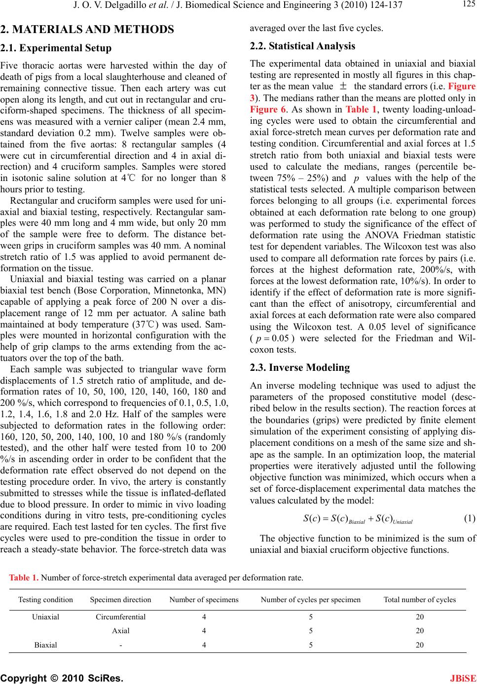 J. O. V. Delgadillo et al. / J. Biomedical Science and Engineering 3 (2010) 124-137 Copyright © 2010 SciRes. 125 JBiSE 2. MATERIALS AND METHODS 2.1. Experimental Setup Five thoracic aortas were harvested within the day of death of pigs from a local slaughterhouse and cleaned of remaining connective tissue. Then each artery was cut open along its length, and cut out in rectangular and cru- ciform-shaped specimens. The thickness of all specim- ens was measured with a vernier caliper (mean 2.4 mm, standard deviation 0.2 mm). Twelve samples were ob- tained from the five aortas: 8 rectangular samples (4 were cut in circumferential direction and 4 in axial di- rection) and 4 cruciform samples. Samples were stored in isotonic saline solution at 4℃ for no longer than 8 hours prior to testing. Rectangular and cruciform samples were used for uni- axial and biaxial testing, respectively. Rectangular sam- ples were 40 mm long and 4 mm wide, but only 20 mm of the sample were free to deform. The distance bet- ween grips in cruciform samples was 40 mm. A nominal stretch ratio of 1.5 was applied to avoid permanent de- formation on the tissue. Uniaxial and biaxial testing was carried on a planar biaxial test bench (Bose Corporation, Minnetonka, MN) capable of applying a peak force of 200 N over a dis- placement range of 12 mm per actuator. A saline bath maintained at body temperature (37℃) was used. Sam- ples were mounted in horizontal configuration with the help of grip clamps to the arms extending from the ac- tuators over the top of the bath. Each sample was subjected to triangular wave form displacements of 1.5 stretch ratio of amplitude, and de- formation rates of 10, 50, 100, 120, 140, 160, 180 and 200 %/s, which correspond to frequencies of 0.1, 0.5, 1.0, 1.2, 1.4, 1.6, 1.8 and 2.0 Hz. Half of the samples were subjected to deformation rates in the following order: 160, 120, 50, 200, 140, 100, 10 and 180 %/s (randomly tested), and the other half were tested from 10 to 200 %/s in ascending order in order to be confident that the deformation rate effect observed do not depend on the testing procedure order. In vivo, the artery is constantly submitted to stresses while the tissue is inflated-deflated due to blood pressure. In order to mimic in vivo loading conditions during in vitro tests, pre-conditioning cycles are required. Each test lasted for ten cycles. The first five cycles were used to pre-condition the tissue in order to reach a steady-state behavior. The force-stretch data was averaged over the last five cycles. 2.2. Statistical Analysis The experimental data obtained in uniaxial and biaxial testing are represented in mostly all figures in this chap- ter as the mean value the standard errors (i.e. Figure 3). The medians rather than the means are plotted only in Figure 6. As shown in Table 1, twenty loading-unload- ing cycles were used to obtain the circumferential and axial force-stretch mean curves per deformation rate and testing condition. Circumferential and axial forces at 1.5 stretch ratio from both uniaxial and biaxial tests were used to calculate the medians, ranges (percentile be- tween 75% – 25%) and values with the help of the statistical tests selected. A multiple comparison between forces belonging to all groups (i.e. experimental forces obtained at each deformation rate belong to one group) was performed to study the significance of the effect of deformation rate using the ANOVA Friedman statistic test for dependent variables. The Wilcoxon test was also used to compare all deformation rate forces by pairs (i.e. forces at the highest deformation rate, 200%/s, with forces at the lowest deformation rate, 10%/s). In order to identify if the effect of deformation rate is more signifi- cant than the effect of anisotropy, circumferential and axial forces at each deformation rate were also compared using the Wilcoxon test. A 0.05 level of significance ( p 0.05p ) were selected for the Friedman and Wil- coxon tests. 2.3. Inverse Modeling An inverse modeling technique was used to adjust the parameters of the proposed constitutive model (desc- ribed below in the results section). The reaction forces at the boundaries (grips) were predicted by finite element simulation of the experiment consisting of applying dis- placement conditions on a mesh of the same size and sh- ape as the sample. In an optimization loop, the material properties were iteratively adjusted until the following objective function was minimized, which occurs when a set of force-displacement experimental data matches the values calculated by the model: () ()() iaxial Uniaxial Sc ScSc (1) The objective function to be minimized is the sum of uniaxial and biaxial cruciform objective functions. Table 1. Number of force-stretch experimental data averaged per deformation rate. Testing condition Specimen direction Number of specimens Number of cycles per specimen Total number of cycles Uniaxial Circumferential 4 5 20 Axial 4 5 20 Biaxial - 4 5 20 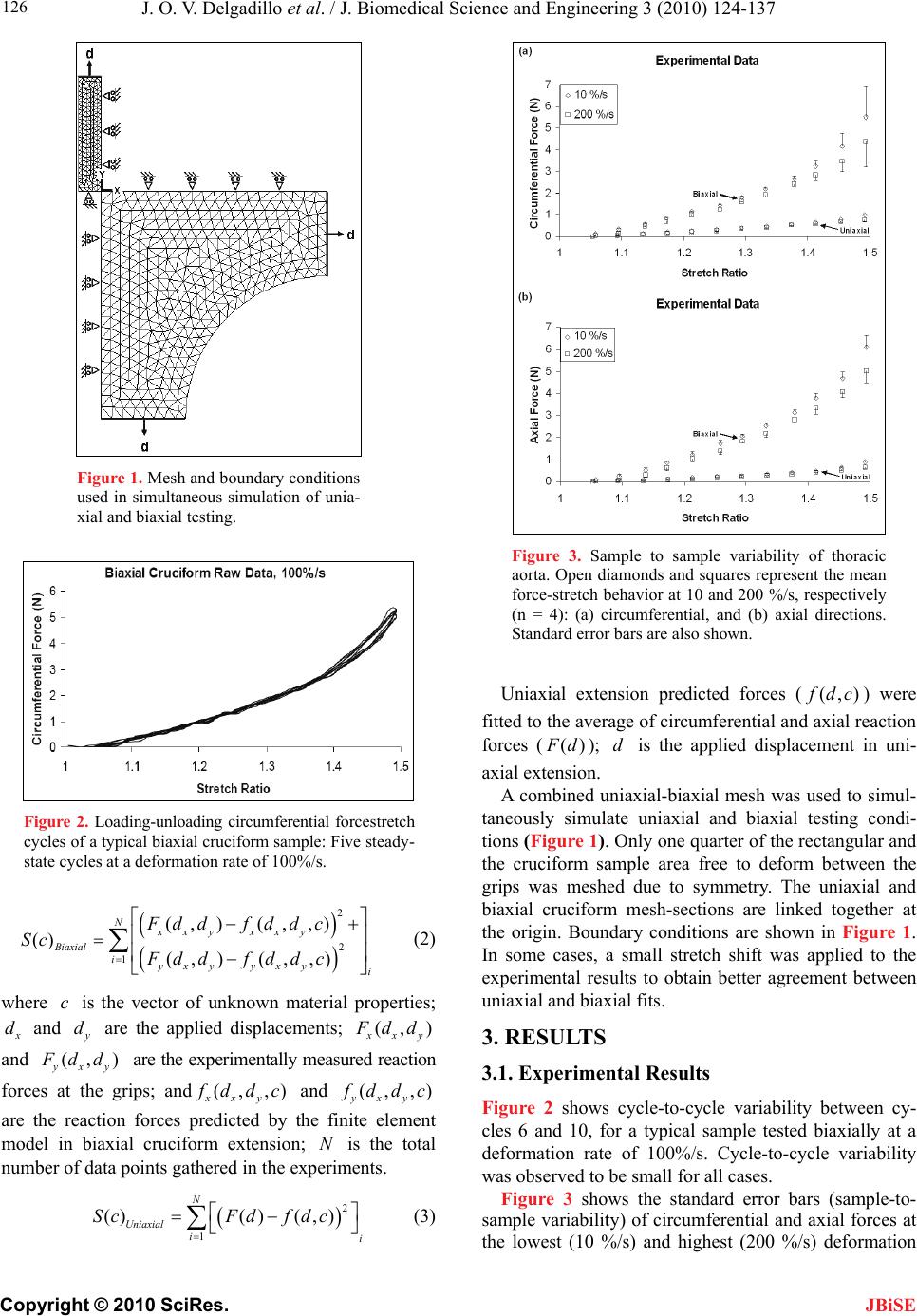 J. O. V. Delgadillo et al. / J. Biomedical Science and Engineering 3 (2010) 124-137 Copyright © 2010 SciRes. 126 JBiSE Figure 1. Mesh and boundary conditions used in simultaneous simulation of unia- xial and biaxial testing. Figure 2. Loading-unloading circumferential forcestretch cycles of a typical biaxial cruciform sample: Five steady- state cycles at a deformation rate of 100%/s. 2 2 1 (, )(, ,) () (, )(, ,) Nxxy xxy Biaxial iyxy yxyi Fd df d d c Sc Fddfddc (2) where is the vector of unknown material properties; c d and are the applied displacements; y d(, ) xy dd and (, ) yyx dd are the experimentally measured reaction forces at the grips; and(,,) xxy ddc and (, ,) yxy ddc are the reaction forces predicted by the finite element model in biaxial cruciform extension; is the total number of data points gathered in the experiments. N 2 1 ()( )( ,) N Uniaxial ii ScFdf dc Figure 3. Sample to sample variability of thoracic aorta. Open diamonds and squares represent the mean force-stretch behavior at 10 and 200 %/s, respectively (n = 4): (a) circumferential, and (b) axial directions. Standard error bars are also shown. Uniaxial extension predicted forces ((,) dc ) were fitted to the average of circumferential and axial reaction forces (() d); is the applied displacement in uni- axial extension. d A combined uniaxial-biaxial mesh was used to simul- taneously simulate uniaxial and biaxial testing condi- tions (Figure 1). Only one quarter of the rectangular and the cruciform sample area free to deform between the grips was meshed due to symmetry. The uniaxial and biaxial cruciform mesh-sections are linked together at the origin. Boundary conditions are shown in Figure 1. In some cases, a small stretch shift was applied to the experimental results to obtain better agreement between uniaxial and biaxial fits. 3. RESULTS 3.1. Experimental Results Figure 2 shows cycle-to-cycle variability between cy- cles 6 and 10, for a typical sample tested biaxially at a deformation rate of 100%/s. Cycle-to-cycle variability was observed to be small for all cases. (3) Figure 3 shows the standard error bars (sample-to- sample variability) of circumferential and axial forces at the lowest (10 %/s) and highest (200 %/s) deformation 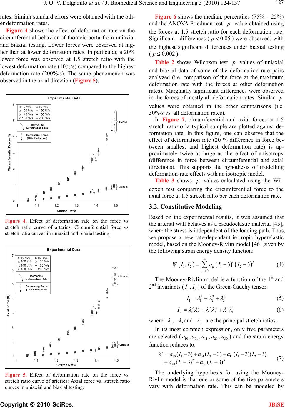 J. O. V. Delgadillo et al. / J. Biomedical Science and Engineering 3 (2010) 124-137 Copyright © 2010 SciRes. 127 JBiSE rates. Similar standard errors were obtained with the oth- er deformation rates. Figure 4 shows the effect of deformation rate on the circumferential behavior of thoracic aorta from uniaxial and biaxial testing. Lower forces were observed at hig- her than at lower deformation rates. In particular, a 20% lower force was observed at 1.5 stretch ratio with the lowest deformation rate (10%/s) compared to the highest deformation rate (200%/s). The same phenomenon was observed in the axial direction (Figure 5). Figure 4. Effect of deformation rate on the force vs. stretch ratio curve of arteries: Circumferential force vs. stretch ratio curves in uniaxial and biaxial testing. Figure 5. Effect of deformation rate on the force vs. stretch ratio curve of arteries: Axial force vs. stretch ratio curves in uniaxial and biaxial testing. Figure 6 shows the median, percentiles (75% – 25%) and the ANOVA Friedman test value obtained using the forces at 1.5 stretch ratio for each deformation rate. Significant differences () were observed, with the highest significant differences under biaxial testing ( p 0.05p 0.002p ). Table 2 shows Wilcoxon test values of uniaxial and biaxial data of some of the deformation rate pairs analyzed (i.e. comparison of the force at the maximum deformation rate with the forces at other deformation rates). Marginally significant differences were observed in the forces of mostly all deformation rates. Similar values were obtained in the other comparisons (i.e. 50%/s vs. all deformation rates). p p In Figure 7, circumferential and axial forces at 1.5 stretch ratio of a typical sample are plotted against de- formation rate. In this figure, one can observe that the effect of deformation rate (20 % difference in force be- tween smallest and highest deformation rate) is ap- proximately twice as large as the effect of anisotropy (difference in force between circumferential and axial directions). This supports the hypothesis of modelling deformation-rate effects with an isotropic model. Table 3 shows values calculated using the Wil- coxon test comparing the circumferential force to the axial force at 1.5 stretch ratio per each deformation rate. p 3.2. Constitutive Modeling Based on the experimental results, it was assumed that the arterial wall behaves as a pseudoelastic material [45], where the stress is independent of the loading path. Thus, we propose a new rate-dependant isotropic hyperelastic model, based on the Mooney-Rivlin model [46] given by the following strain energy density function: 121 2 ,0 ,3 i ij ij WIIa II 3 j (4) The Mooney-Rivlin model is a function of the 1st and 2nd invariants (1 ,2 ) of the Green-Cauchy tensor: 22 11 2 I2 3 (5) 22 22 22 2122331 I (6) where 1 , 2 and 3 are the principal stretch ratios. In its most common expression, only five parameters are selected (, , ,,) and the strain energy function reduces to: 10 a01 a11 a20 a30 a 10101211 12 23 20 130 1 (3)(3)(3)(3 (3) (3) WaIaIaI I aI aI ) (7) The underlying hypothesis for using the Mooney- Rivlin model is that one or some of the five parameters vary with deformation rate. This can be modeled by  J. O. V. Delgadillo et al. / J. Biomedical Science and Engineering 3 (2010) 124-137 Copyright © 2010 SciRes. 128 Figure 6. Deformation rate effect on (a, b) uniaxial and (c, d) biaxial forces at maximum stretch ratio (1.5 ): (a, c) circumferential and (b, d) axial direction. Table 2. Effect of deformation rate:Wilcoxon test p values. Type of test Uniaxial Biaxial Force Circumferential Axial Circumferential Axial Deformation rate (%/s) 200 10 0.07 0.07 0.07 0.07 50 0.07 0.07 0.07 0.07 100 0.14 0.07 0.07 0.07 120 0.07 0.07 0.07 0.07 140 0.07 0.07 0.07 0.07 160 0.07 0.07 0.07 0.07 180 0.37 0.07 0.72 0.42 Table 3. Effect of anisotropy (Circumferential vs. axial forces, n = 4): Wilcoxon test p values. Deformation rate (%/s) Uniaxial Biaxial 10 0.47 0.47 50 0.14 0.47 100 0.27 0.47 120 0.14 0.47 140 0.27 0.47 160 0.14 0.47 180 0.14 0.47 200 0.14 0.47 JBiSE  J. O. V. Delgadillo et al. / J. Biomedical Science and Engineering 3 (2010) 124-137 Copyright © 2010 SciRes. 129 JBiSE Table 4. First simulation results (material parameters) of uniaxial and biaxial cruciform tests. M-R Fitted Parameter Values (kPa) Deformation Rate (%/s) 10 a 01 a 11 a 20 a 30 a SUM/n x 10-03 (n = 24) 10 9.25 7.57 5.77 6.94 4.43 2.69 50 9.21 7.45 5.45 6.58 3.64 2.09 100 8.90 7.23 5.51 6.66 3.86 1.76 120 9.46 7.66 5.38 6.52 3.03 1.66 140 9.96 8.07 5.30 6.45 2.36 3.45 160 9.22 7.47 5.29 6.40 3.24 2.72 180 9.07 7.32 5.34 6.49 2.95 2.80 200 8.86 7.17 5.24 6.36 2.80 1.90 Linear Regression Coefficients & R2 ij aAB A 9.32 7.60 5.69 6.85 4.27 B x 10-03 -0.70 -0.90 -2.40 -2.50 -8.20 R2 0.01 0.04 0.80 0.78 0.65 Table 5. Second simulation results (material parameters) of uniaxial and biaxial cruciform tests. M-R Fitted Parameter Values (kPa) Deformation Rate (%/s) 10 a 01 a 11 a 20 a 30 a SUM/n x 10-03 (n = 24) 10 4.99 2.64 50 3.66 2.18 100 3.74 1.88 120 3.16 1.68 140 9.24 7.79 5.41 2.75 6.55 3.56 160 3.06 2.83 180 2.72 2.98 200 2.26 1.98 Linear Regression Coefficients & R2 ij aAB A - - - - 4.76 B x 10-03 - - - - -12.20 R2 - - - - 0.88 Figure 7. Comparison of the effect of deformation rate versus the effect of anisotropy. Typical sample forces at maximum stretch ratio (1.5). making these parameters functions of the deformation rate. Those relationships are explored in this work. 3.3. Inverse Modeling Results Initially, all five Mooney-Rivlin parameters were all- owed to vary while being limited to a 10-4 kPa to 104 kPa value range. Table 4 summarizes the fitted parameters obtained for the uniaxial and biaxial cruciform force vs. stretch ratio curve averaged for each deformation rate. In a second simulation only parameter was al- lowed to vary because this was the parameter with the highest slope (absolute value of ) in the linear regres- sions reported in Table 4. The remaining parameters were maintained constant by using the average of the fitted values obtained for all deformation rates. The fit- ted parameters obtained are summarized in Table 5. The sum of least squares (last column in Tables 4 and 5) were almost unchanged when the first four parameters were kept constant, supporting the hypothesis that only varies with deformation rate. 30 a B 30 a Other fits were performed assuming that 11200aa model could be reduced to a simpler form (Table 6). First, parameters 10 a, 01 a anawere wed to vary. The highest regression coefficient (ab- solute value of B) and the highest correlationcoeffi- cient (2 R) were tained for 30 a. Thus pmeters 10 a to see if the allo a d 30 raob 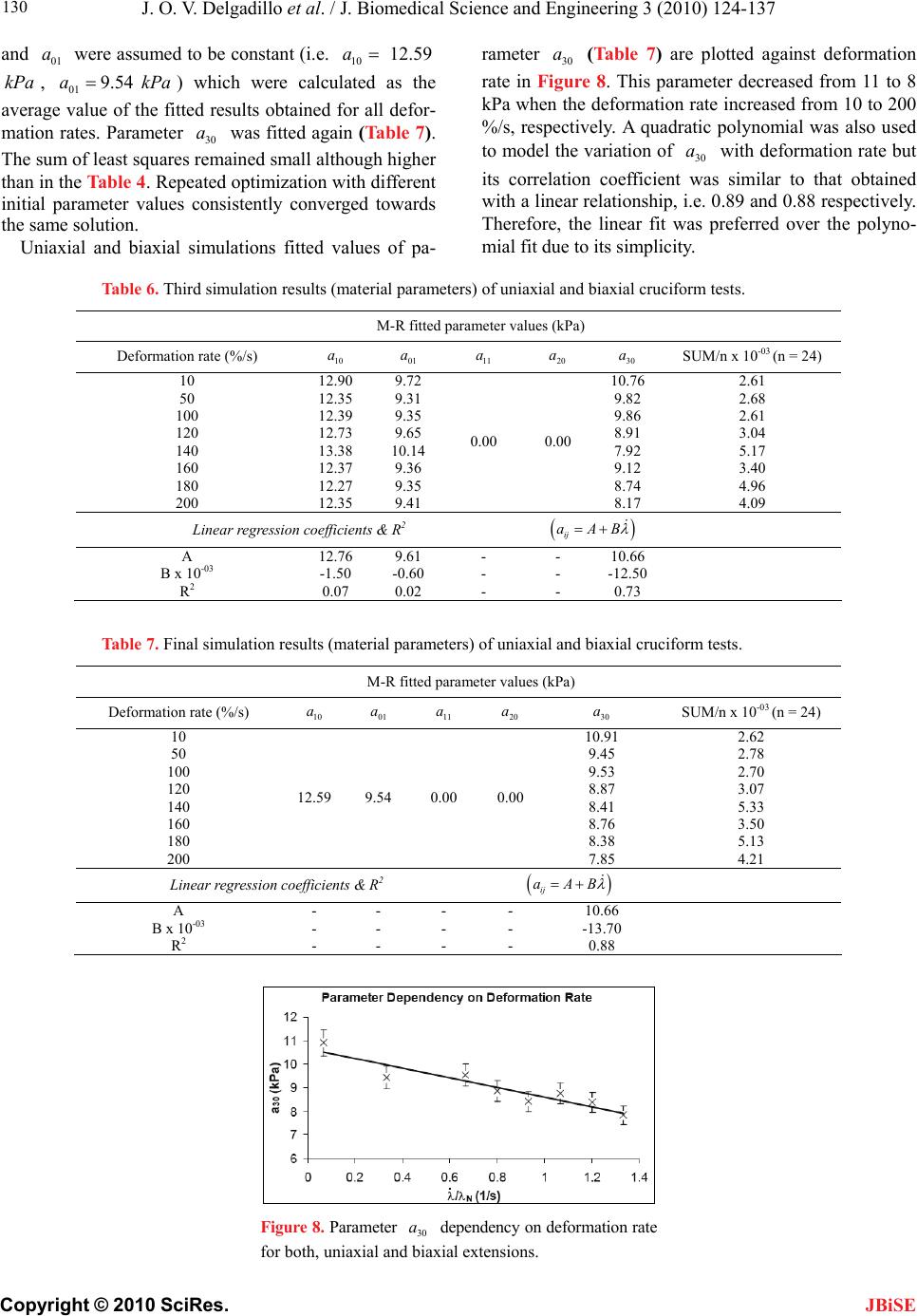 J. O. V. Delgadillo et al. / J. Biomedical Science and Engineering 3 (2010) 124-137 Copyright © 2010 SciRes. 130 wer e JBiSE and 01 a e assumd to be constant (i.e. 10 12.59a 9Pe calculated as the average value of the fitted results obtained for all defor- mation rates. Parameter 30 a was fitted again (Table 7). The sum of least squares remained small although higher than in the Table 4. Repeated optimization with different initial parameter values consistently converged towards the same solution. kPa , 01 .54aka) which wer Uniaxial and biaxial simulations fitted values of pa- rameter (Table 7) are plotted against deformation rate in Figure 8. This parameter decreased from 11 to 8 kPa when the deformation rate increased from 10 to 200 %/s, respectively. A quadratic polynomial was also used to model the variation of with deformation rate but its correlation coefficient was similar to that obtained with a linear relationship, i.e. 0.89 and 0.88 respectively. Therefore, the linear fit was preferred over the polyno- mial fit due to its simplicity. 30 a 30 a Table 6. Third simulation results (material parameters) of uniaxial and biaxial cruciform tests. M-R fitted parameter values (kPa) Deformation rate (%/s) 10 01 aa 11 a 20 a 30 a SUM/n x 10-03 (n = 24) 10 12.90 9.72 10.76 2.61 50 12.35 9.31 9.82 2.68 100 12.39 9.35 9.86 2.61 120 12.73 9.65 8.91 3.04 140 13.38 10.14 7.92 5.17 160 12.37 9.36 9.12 3.40 180 12.27 9.35 8.74 4.96 200 12.35 9.41 0.00 0.00 8.17 4.09 Linear regression coefficients & R2 ij aAB A 12.76 9.61 - - 10.66 B x 10-03 -1.50 -0.60 - - -12.50 R2 0.07 0.02 - - 0.73 Table 7. Final simulation results (material parameters) of uniaxial and biaxial cruciform tests. M-R fitted parameter values (kPa) Deformation rate (%/s) 10 a 01 a 11 a 20 a 30 a SUM/n x 10-03 (n = 24) 10 10.91 2.62 50 9.45 2.78 100 9.53 2.70 120 8.87 3.07 140 8.41 5.33 160 8.76 3.50 180 8.38 5.13 200 12.59 9.54 0.00 0.00 7.85 4.21 Linear regression coefficients & R2 ij aAB A - - - - 10.66 B x 10-03 - - - - -13.70 R2 - - - - 0.88 Figure 8. Parameter dependency on deformation rate for both, uniaxial and biaxial extensions. 30 a 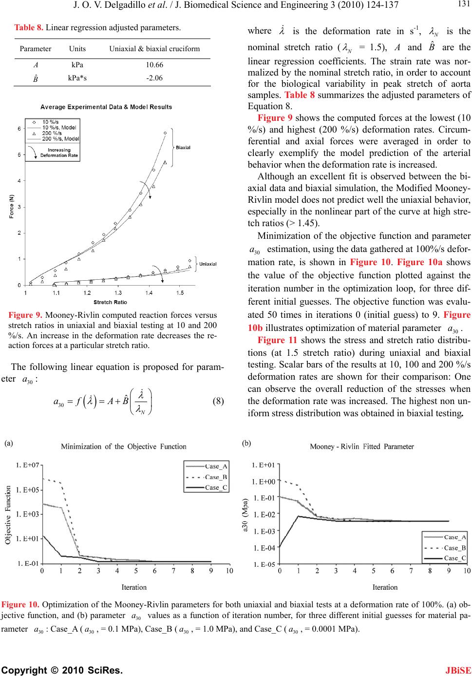 J. O. V. Delgadillo et al. / J. Biomedical Science and Engineering 3 (2010) 124-137 Copyright © 2010 SciRes. 131 JBiSE Table 8. Linear regression adjusted parameters. Parameter Units Uniaxial & biaxial cruciform kPa 10.66 ˆ kPa*s -2.06 Figure 9. Mooney-Rivlin computed reaction forces versus stretch ratios in uniaxial and biaxial testing at 10 and 200 %/s. An increase in the deformation rate decreases the re- action forces at a particular stretch ratio. The following linear equation is proposed for param- eter : 30 a 30 ˆ N af AB where is the deformation rate in s-1, N is the nominal stretch ratio (N = 1.5), and are the linear regression coefficients. The strain rate was nor- malized by the nominal stretch ratio, in order to account for the biological variability in peak stretch of aorta samples. Table 8 summarizes the adjusted parameters of Equation 8. ˆ B Figure 9 shows the computed forces at the lowest (10 %/s) and highest (200 %/s) deformation rates. Circum- ferential and axial forces were averaged in order to clearly exemplify the model prediction of the arterial behavior when the deformation rate is increased. Although an excellent fit is observed between the bi- axial data and biaxial simulation, the Modified Mooney- Rivlin model does not predict well the uniaxial behavior, especially in the nonlinear part of the curve at high stre- tch ratios (> 1.45). Minimization of the objective function and parameter estimation, using the data gathered at 100%/s defor- mation rate, is shown in Figure 10. Figure 10a shows the value of the objective function plotted against the iteration number in the optimization loop, for three dif- ferent initial guesses. The objective function was evalu- ated 50 times in iterations 0 (initial guess) to 9. Figure 10b illustrates optimization of material parameter . 30 a 30 Figure 11 shows the stress and stretch ratio distribu- tions (at 1.5 stretch ratio) during uniaxial and biaxial testing. Scalar bars of the results at 10, 100 and 200 %/s deformation rates are shown for their comparison: One can observe the overall reduction of the stresses when the deformation rate was increased. The highest non un- iform stress distribution was obtained in biaxial testing. a (8) Figure 10. Optimization of the Mooney-Rivlin parameters for both uniaxial and biaxial tests at a deformation rate of 100%. (a) ob- jective function, and (b) parameter values as a function of iteration number, for three different initial guesses for material pa- rameter : Case_A (, = 0.1 MPa), Case_B (, = 1.0 MPa), and Case_C (, = 0.0001 MPa). 30 a 30 a30 a30 a30 a  J. O. V. Delgadillo et al. / J. Biomedical Science and Engineering 3 (2010) 124-137 Copyright © 2010 SciRes. 132 JBiSE Figure 11. Deformed configurations at 1.50 nominal stretch ratio for uniaxial and cruciform mesh: Distribution of (a) x stress and (b) stretch ratio in the principal direction. The stress and stretch distributions at 10, 100, and 200 %/s are shown inside the tables. Figure 12. Parameter a30 dependency on deformation rate for uniaxial extension: (a) circumferential and (b) axial directions. 3.3.2. Uniaxial Fit In order to improve uniaxial simulations, two objective functions were defined, one for each direction: 2 1 ()( )(,) N xx xx ii ScFdfdc (9) 2 1 ()( )( ,) N yy yy ii ScFdfdc (10) These objective functions were used to better predict the uniaxial extension experimental data. Different mat- erial properties were obtained for the circumferential and for the axial directions. Uniaxial simulations fitted values of parameter per deformation rates are shown in Figure 12. This para- meter was reduced roughly from 33 to 23 kPa when the deformation rate was increased, following the same 30 a  J. O. V. Delgadillo et al. / J. Biomedical Science and Engineering 3 (2010) 124-137 Copyright © 2010 SciRes. 133 JBiSE Figure 13. Mooney-Rivlin computed reaction forces versus stretch ratios in uniaxial testing at a deforma- tion rate of 100 %/s. Table 9. Mooney-Rivlin fitted parameters in uniaxial extension. Parameters (kPa) Mooney-Rivlin Circumferential Axial a10 9.56 9.56 a01 18.01 7.87 a11 0.00 0.00 a20 0.00 0.00 33.64 30.62 ˆ -5.32 -4.40 trend in circumferential and axial directions. It was also observed that material parameter changed linearly as a function of the deformation rate. 30 a Table 9 summarizes Mooney-Rivlin fitted parameters obtained just for uniaxial tests. The values of ob- tained per deformation rate were almost 4 times greater than values calculated with the combined uniaxial- biaxial simulation. Parameters and remained almost unchanged in both the uniaxial and combined uniaxial-biaxial simulations, with exception of parameter in circumferential direction (i.e. 18 kPa). 30 a 30 a 10 a01 a 01 a The computed circumferential and axial forces ob- tained using the Mooney-Rivlin fitted parameters from Table 9 in uniaxial tests, at a deformation rate of 100%/s, are shown in Figure 13. Uniaxial behaviour in both di- rections was well predicted. Figure 14 shows the stress and stretch ratio distribu- tion of rectangular samples. The reduction of the stresses as the deformation rate increases is observed when the stress distribution at each deformation rate is compared (scalar bars at 10, 100 and 200 %/s). 4. DISCUSSION Contrary to the conventional understanding of biological Figure 14. Deformed configurations at 1.50 nominal stretch ratio for uniaxial mesh using the mate- rial parameters of Table 6.3 (Circumferential direction): distribution of (a) x stress and (b) stretch ratio in the principal direction. The stress and stretch distributions at 10, 100, and 200 %/s are shown inside the tables. tissue behaviour, it was discovered in this study that the stiffness of thoracic aorta decreases with deformation rate, which was confirmed by the use of two statistical methods. Overall significant differences () in the mechanical forces of uniaxial and biaxial experiments were found using the ANOVA Friedman statistic test. In addition, the Wilcoxon test help us to observe which particular pair of deformation rates likely had a tendency to be significantly different (i.e. almost all deformation rates were different than 200%/s, p). An increase in the sample size for further studies will certainly reduce the Wilcoxon test values obtained. 0.02p 0.07 p Giles et al. [22] observed a similar behaviour in load controlled planar biaxial laboratory tests of myocardium and skin samples. Hu and Desai [18] studied the varia- tion of the elastic modulus of pig liver tissue at different deformation rates under compression tests, and found that at higher strain rates the liver has an apparently lower resistance (i.e. softer) to deformation than at lower deformation rates. However, under uniaxial displace-  J. O. V. Delgadillo et al. / J. Biomedical Science and Engineering 3 (2010) 124-137 Copyright © 2010 SciRes. 134 JBiSE ment controlled tests, Pioletti et al. [7] found that an increase in the deformation rate results in a stiffer mate- rial response. In their work, they submitted ligament samples to deformation rates within 0.1 – 40%/s in as- cending order. In the present study, thoracic aortas were tested over a 10 – 200%/s range of deformation rates. In both, uniaxial and biaxial tests, the peak force on the arterial samples was around 20% smaller at a deforma- tion rate of 200%/s than at 10%/s (Figures 3 and 4). These results were observed on the average of the five steady-state loading cycles, after five-preconditioning cycles for each deformation rate. However, similar re- sults were also observed on the first loading cycle at each deformation rate, eliminating the possibility of this behavior being due to pre-conditioning. The experimen- tal procedure was validated by repeating the same ex- periments on latex and nitrile samples. As expected, the effect of deformation rate was opposite in these rubbers to what was observed in the arterial samples. An ex- periment without any sample was performed to measure the combined effects of inertia, friction, and water drag force, which were found to be negligible, i.e. less than 10 % of the effect of deformation rate. Sample variability between circumferential and axial force vs. stretch ratio curves was found to be lower than the effect of deformation rate, supporting the use of an isotropic constitutive equation to predict the behavior of the arterial wall. Isotropic models have also been used to model the artery in other studies [43,47-50]. Forces in- stead of stresses were reported here due to the non-homogeneous stress and strain distributions found in speci- mens subjected to biaxial tests, where the highest and lowest stresses are found near the curved boundaries and near the center of the sample, respectively [51]. Moreover, researchers who are focused (like us) on ex- perimental rather than theoretical work will appreciate to report the data as raw as possible. The main constituents of arterial tissues are collagen and elastin. The elastic response of arteries is largely due to elastin because elastin is about 1000 times more ex- tensible than collagen. The proportion of elastin to the other arterial constituents is the highest in the aorta. Ela- stin chains are crosslinked together to form rubberlike, elastic fibers [52]. Each elastin molecule uncoils into a more extended conformation when the fiber is stretched and recoils spontaneously as soon as the stretching force is relaxed. Its elasticity is based on changes in the en- tropy of the molecular chains, while the material is de- formed. An imposed strain increases the order in the molecular network and thus decreases its entropy. Ac- cording to the thermodynamic laws, the network would try to recover its former shape, increasing their entropy. One possible explanation for the observed phenomenon is that when elastin is stretched at high rates it would attain a highly oriented conformation and as a result the cross-links would not be able to bear the load due to slippage. However, as the stretch occurs at lower rates, the elastin molecules would have more time ava- ilable to adjust in order to prevent slippage of the cross-links and as a result would be able to bear a higher load. This effect can be viewed as an energy dissipation effect where at high rates of stretching the energy is dissipated rather by the associative flow and the slippage between cross-links. At lower rates the energy dissipation is less. This effect is similar to the stretching behaviour of branched polymers when compared to that of their linear counterparts [53,54]. Here elastin at high extensional rates would behave more like a linear polymer where the linear polymers can slip one past the other to exhibit a reduced load mainly due to high oriented conformation imposed by the high stretching rate. On the other hand, elastin at low extensional rates would behave like a branched polymer where the presence of branches pre- vent cross-linking slippage and as a result bear higher loads. Moreover, Trepat et al. [55] subjected human airway smooth muscle cells to a transient stretch-unstretch ma- neuver with zero residual macroscale strain, observing that the cell promptly fluidizes and then slowly resolidi- fies. Therefore, is it possible that changes in the align- ment and configuration of adjacent fibers within the ex- tracellular matrix occurs as soon as one fiber begins to shear over the other (i.e. fluid-like behavior), making softer the overall response in the tissue when stretching the arterial sample at the highest deformation rate (minimum relaxation in the tissue due to short testing time). At lower deformation rates, the fibers have more time to move back to their original configuration, thus restraining their ability to flow (stiffer response). The constitutive equation selected here is capable of representing the nonlinear elastic behavior of the artery, including the effect of deformation rate, with only four parameters. It produces a unique curve fitting solution to experimental results for each deformation rate. More importantly, it was observed that Mooney Rivlin pa- rameters and were not a function of the de- formation rate. This could imply that they are related to the elastic behavior of the artery. A linear relationship was obtained between parameter and the deforma- tion rate, where the partially elastic contribution is given by coefficient 10 a01 a 30 a and the deformation rate response is given by coefficient. ˆ B As shown in Figure 9, the model better fits the biaxial data than the uniaxial data. Using higher weights for the uniaxial least square differences, it was possible to ob- tain a better fit for uniaxial data, at the expense of a de- terioration of the fit for biaxial data. The use of material parameters and did not improve the fits sig- nificantly enough to justify increasing the complexity of 11 a20 a  J. O. V. Delgadillo et al. / J. Biomedical Science and Engineering 3 (2010) 124-137 Copyright © 2010 SciRes. 135 JBiSE the model with these two extra parameters. The use of anisotropic constitutive equations in future studies might reduce this discrepancy between predicted and experi- mental forces in uniaxial direction. Clinical results have shown that slow balloon inflation might reduce restenosis. It was hypothesized that the slower deformation rate gives as a result lower intr- amural stresses and lower arterial injury. This hypothesis is contradictory to our results, which would indicate that a lower inflation rate would result in higher intramural stresses. Other mechanisms might play a role in leading to lower restenosis rates, such as endothelium denuda- tion or artery injury being dependent on stretch ratio rather than on intramural stress. 5. CONCLUSIONS In the present study, the effect of deformation rate on the mechanical behavior of arteries in vitro under uniaxial and biaxial extensions was investigated. It was found that the loading force at a stretch ratio of 1.5 is reduced by 20 % when the deformation rate is increased from 10 to 200 %/s, implying that the stiffness of arteries de- creases with deformation rate. This behavior might be a consequence of the faster fluidization and small resolidi- fication that occurs in the cell at higher deformation rates. This effect of deformation rate was observed to be higher than the effect of anisotropy. The development of an isotropic hyperelastic rate-dependent constitutive model, derived from the Mooney-Rivlin hyperelastic model, is capable of representing this behavior. In its proposed form, the model has only 4 parameters, only one of which varies with deformation rate. The small number of material parameters and simple formulation increase the applicability of this model to numerical simulations. The inverse relationship between stiffness and deformation rate raises doubts on the hypothesized relationship between intramural stress, arterial injury, and restenosis. Future work might be helpful in order to account the entire loading history of the arterial wall by performing additional characterizations such as relaxation time ex- periments, and with the aim of a viscoelastic model. The ratio between maximum stretch with balloon and infla- tion time might be computed as well to observe if the same phenomenon appears. 6. ACKNOWLEDGEMENTS This research was possible thanks to the PhD scholarship given by the Mexican Council of Science and Technology (Consejo Nacional de Ciencia y Tecnología), CONACYT. The authors would also like to thank Marc-Andre Rainville for his guidance and assistance in sample preparation and mechanical testing. REFERENCES [1] Thornton, G.M., Schwab, T.D. and Oxland, T.R. (2007a) Fatigue is more damaging than creep in ligament re- vealed by modulus reduction and residual strength. An- nals of Biomedical Engineering, 35, 1713-1721. [2] Thornton, G.M., Schwab, T.D. and Oxland, T.R. (2007b) Cyclic loading causes master rupture and strain rate than static loading in medial collateral ligament at high stress. Clinical Biomechanics, 22, 932-940. [3] Provenzano, P., Lakes, R., Keenan, T. and Vanderby Jr., R. (2001) Nonlinear ligament viscoelasticity. Annals of Biomedical Engineering, 29, 908-914. [4] Pioletti, D. And Rakotomanana, L.R. (2000) Non-linear viscoelastic laws for soft biological tissues. Eur. J. Mech. A/Solids, 19, 749-759. [5] Pioletti, D., Rakotomanana, L.R., Benvenuti, J.F. and Leyvraz, P.F. (1998) Viscoelastic constitutive law in large deformations: Application to human knee ligaments and tendons. Journal of Biomechanics, 31, 753-757. [6] Kwan, M.K., Lin, T.H.C. and Woo, S.L.Y. (1993) On the viscoelastic properties of the anteromedial bundle of the anterior cruciate ligament. J. Biomechanics, 26, 447-452. [7] Pioletti, D., Rakotomanana, L.R. and Leyvraz, P.F. (1999) Strain rate effect on the mechanical behavior of the ante- rior cruciate ligament-bone complex. Medical Engineer- ing & Physics, 21, 95-100. [8] Haut, R.C. (1983) Age-dependent influence of strain rate on the tensile failure of rat-tail tandon. Journal of Bio- mechanical engineering, 105, 296-299. [9] Haut, R.C. and Little, R.W. (1972) A constitutive equa- tion for collagen fibers. Journal of Biomechanics, 5, 423- 430. [10] Gay, R.E., Ilharreborde, B., Zhao, K., Boumediene, E. and An, K.N. (2008) The effect of loading rate and degenera- tion on neutral region motion in human cadaveric lumbar motion segments. Clinical Biomechanics, 23, 1-7. [11] Wang, J.L., Parnianpour, M., Shirazi-Adl, A. and Engin, A.E. (1999) Rate effect on sharing of passive lumbar motion segment under load-controlled sagittal flexion: Viscoelastic finite element analysis. Theoretical and Ap- plied Fracture Mechanics, 32, 119-128. [12] Yingling, V.R., Callaghan, J.P. and McGill, S.M. (1997) Dynamic loading affects the mechanical properties and failure site of porcine spines. Clinical Biomechanics, 12, 301-305. [13] Tran, N.T., Watson, N.A., Tencer, A.F., Ching, R.P. and Anderson, P.A. (1995) Mechanism of the burst fracture in the thoracolumbar spine: The effect of loading rate. Spine, 20, 1984-1988. [14] De Smet, E., Jaecques, S.V.N., Jansen, J.J., Walboomers, F., Van Der Sloten, J. and Naert, I.E. (2007) Effect of constant strain rate, composed of varying amplitude and frequency, of early loading on peri-implant bone (re)mo- deling. Journal of Clinical Periodontology, 34, 618-624. [15] Ebacher, V., Tang, C., McKay, H., Oxland, T.R., Guy, P. and Wang, R. (2007) Strain redistribution and cracking behavior of human bone during bending. Bone, 40, 1265- 1275. [16] Hsieh, Y.F., Wang, T. and Turner, C.H. (1999) Viscoe- lastic response of the rat loading model: Implications for studies of strain-adaptive bone formation. Bone, 25 , 379- 382. [17] Schaffler, M.B., Radin, E.L. and Burr, D.B. (1989) Me-  J. O. V. Delgadillo et al. / J. Biomedical Science and Engineering 3 (2010) 124-137 Copyright © 2010 SciRes. 136 JBiSE chanical and morphological effects of strian rate on fa- tigue of compact bone. Bone, 10, 207-214. [18] Hu, T. and Desai, J.P. (2004) Soft-tissue material proper- ties under large deformation: Strain rate effect. Proceed- ings of the 26th Annual International Conference of the IEEE EMBS, San Francisco, CA, USA (September 1-5, 2004), 2758-2761. [19] Doehring, T.C., Carew, E.O. and Vesely, I. (2004) The effect of strain rate on the viscoelastic response of aortic valve tissue: A direct-fit approach. Annals of Biomedical Engineering, 32, 223-232. [20] Wells, S. and Sacks, M.S. (2002) Effects of fixation pressure on the biaxial mechanical behavior of porcine bioprosthetic heart valves with long-term cyclic loading. Biomaterials, 23, 2389-2399. [21] Demer, L.L. and Yin, F.C.P. (1983) Passive biaxial me- chanical properties of isolated canine myocardium. Jour- nal of Physiology, 339, 615-630. [22] Giles, J.M., Black, A.E. and Bischoff, J.E. (2007) Ano- malous rate dependence of the preconditioned response of soft tissue during load controlled deformation. Journal of Biomechanics, 40, 777-785. [23] Nekouzadeh, A., Pryse, K.M., Elson, E.L. and Genin, G. M. (2007) A simplified approach to quasi-linear viscoe- lastic modeling. Journal of Biomechanics, 40, 3070-3078. [24] Sarver, J.J., Robinson, P.S. and Elliott, D.M. (2003) Me- thods for quasi-linear viscoelastic modeling of soft tissue: Application to incremental stress-relaxation experiments. Journal of Biomechanical Engineering, 125, 754-785. [25] Vena, P., Gastaldi, D. and Contro, R. (2006) A constitu- ent-based model for the nonlinear viscoelastic behavior of ligaments. Journal of Biomechanical Engineering, 128, 449-457. [26] Zhang, W., Chen, H.Y. and Kassab, G.S. (2007) A rate- insensitive linear viscoelastic model for soft tissues. Bio- materials, 28, 3579-3586. [27] Schwartz, R.S., Holmes Jr., D.R. and Topol, E.J. (1992) The restenosis paradigm revisited: An alternative propo- sal for cellular mechanism. Journal of the American College of Cardiology, 20, 1284-1293. [28] Tenaglia, A.N., Quigley, P.J., Kereiakes, D.J., Abbotts- mith, C.W., Phillips, H.R., Tcheng, J.E., Rendall, D. and Ohman, E.M. (1992) Coronary angioplasty performed with gradual and prolonged inflation using a perfusion balloon catheter: Procedural success and restenosis rate. Am. Heart J., 124, 585-589. [29] Miketic, S., Carlsson, J. and Tebbe, U. (1998) Influence of gradually increased slow balloon inflation on resteno- sis after coronary angioplasty. American Heart Journal, 135, 709-713. [30] Timmis, S.B.H., Hermiller, J.B., Burns, W.H., Meyers, S. N. and Davidson, C.J. (1999) Comparison of immediate and in-hospital results of conventional balloon and perfu- sion balloon angioplasty using intracoronary ultrasound. American Journal of Cardiology, 83, 311-316. [31] Eltchaninoff, H., Cribier, A., Koning, R., Chan, C., Jolly, N., Tan, A. and Letac, B. (1996) Effects of prolonged se- quential balloon inflations on results of coronary angio- plasty. Am. J. Cardiol, 77, 1062-1066. [32] Ohman, E.M., Marquis, J.F., Ricci, D.R., Brown, R.I., Knudtson, M.L., Kereaikes, D.J., Samaha, J.K., Margolis, J.R., Niederman, A.L. and Dean, L.S. (1994) A random- ized comparison of the effects of gradual prolonged ver- sus standard primary balloon inflation on early and late outcome: Results of a multicenter clinical trial. Perfusion balloon catheter study group, Circulation, 89, 1118-1125. [33] Umeda, H., Iwase, M., Kanda, H., Izawa, H., Nagata, K., Ishiki, R., Sawada, K., Murohara, T. and Yokota, M. (2004) Promising efficacy of primary gradual and pro- longed balloon angioplasty in small coronary arteries: A randomized comparison with cutting balloon angioplasty and conventional balloon angioplasty. American Heart Journal, 147, 1-8. [34] Weiss, T., Leibovitz, D., Katz, I., Danenberg, C., Var- shitsky, B. and Lotan, C. (2007) The value of computer- ized angioplasty in patients undergoing coronary stenting: A prospective, randomized trial. Am. J. Cardiol., 100, 118L. [35] Thériault, P., Terriault, P., Brailovski, V. and Gallo, R. (2006) Finite element modeling of a progressively ex- panding shape memory stent. Journal of Biomechanics, 39, 2837-2844. [36] Gasser, T.C. and Holzapfel, G.A. (2007) Modeling plaque fissuring and dissection during balloon angioplasty in- tervention. Annals of Biomedical Engineering, 35, 711- 723. [37] Holzapfel, G.A., Stadler, M. and Schulze-Bauer, C.A. (2002) A layer-specific three-dimensional model for the simulation of balloon angioplasty using magnetic reso- nance imaging and mechanical testing. Ann. Biomed. Eng, 30, 753-767. [38] Lally, C., Dolan, F. and Prendergast, P.J. (2005) Cardio- vascular stent design and vessel stresses: A finite element analysis. Journal of Biomechanics, 38, 1574-1581. [39] Oh, S., Kleinberger, M. and McElhaney, J.H. (1994) Finite-element analysis of balloon angioplasty. Med. & Biol. Eng. & Comput., 32, S108-S114. [40] Wu, W., Qi, M., Liu, X.P., Yang, D.Z. and Wang, W.Q. (2007) Delivery and release of nitinol stent in carotid ar- tery and their interactions: A finite element analysis. Journal of Biomechanics, 40, 3034-3040. [41] Lally, C., Reid, A.J. and Prendergast, P.J. (2004) Elastic behavior of porcine coronary artery tissue under uniaxial and equibiaxial tension. Ann. Biomed. Eng., 32, 1355- 1364. [42] Okamoto, R.J., Wagenseil, J.E., Delong, W.R., Peterson S.J., Kouchoukos, N.T. and Sundit III, T.M. (2002) Me- chanical properties of dilated human ascending aorta. Ann. Biomed. Eng., 30, 624-635. [43] Prendergast, P.J., Lally, C., Daly, S., Reid, A.J., Lee T. C., Quinn, D. and Dolan, F. (2003) Analysis of prolapse in cardiovascular stents: A constitutive equation for vas- cular tissue and finite-element modelling. Journal of Bio- mechanical Engineering, 125, 692-699. [44] Waldman, S.D. and Lee, J.M. (2002) Boundary condi- tions during biaxial testing of planar connective tissues: Part 1: Dynamic behavior. Journal of Materials Science, Materials in Medicine, 13, 933-938. [45] Fung, Y.C. (1993) Biomechanics: Mechanical properties of living tissues, 2nd edition, Springer-Verlag, New York, 261-262. [46] Mooney, M.A. (1940) Theory of large elastic deforma- tion. J. Appl. Phys., 11, 582-592. [47] Raghavan, M.L. and Vorp, D.A. (2000) Toward a bio-  J. O. V. Delgadillo et al. / J. Biomedical Science and Engineering 3 (2010) 124-137 Copyright © 2010 SciRes. 137 JBiSE mechanical tool to evaluate rupture potential of abdomi- nal aortic aneurysm: Identification of a finite strain con- stitutive model and evaluation of its applicability. Jour- nal of Biomechanics, 33, 475-482. [48] Scotti, C.M. and Finol, E.A. (2007) Compliant biomecha- nics of abdominal aortic aneurysms: A fluid-structure in- teraction study. Computers & Structures, 85, 1097-1113. [49] Tezduyar, T.E., Sathe, S., Cragin, T., Nanna, B., Conklin B.S., Pausewang, J. and Schwaab, M. (2007) Modelling of fluid-structure interactions with the space-time finite elements: Arterial fluid mechanics. Int. J. Num. Meth. Fluids, 54, 901-922. [50] Wang, D.H.J., Makaroun, M., Webster, M.W. and Vorp, D.A. (2001) Mechanical properties and microstructure of intraluminal thrombus from abdominal aortic aneurysm. Journal of Biomechanical Engineering, 123, 536-539. [51] Virues-Delgadillo, J.O., Delorme, S., Diraddo, R. and Hatzikiriakos, S.G. (2007) Effect of deformation rate on the mechanical properties of rectangular and cruciform arterial samples: Uniaxial and biaxial testing. Proceed- ings ASME 2007 Summer Bioengineering Conference Keystone, Colorado, USA. [52] Shadwick, R.E. (1999) Mechanical design in arteries. J. Exp. Biol., 202, 3305-3313. [53] McLeish, T.C.B. and Larson, R.G. (1998) Molecular con- stitutive equations for a class of branched polymers: The pom-pom model. J. Rheol, 42, 81-110. [54] Sentmanat, M., Muliawan, E.B. and Hatzikiriakos, S.G. (2005) Fingerprinting the processing of polyethylenes from transient extensional flow and peel experiments in the melt state. Rheologica Acta, 44, 1-15. [55] Trepat, X., Deng, L., An, S.S., Navajas, D., Tschumper- lin, D.J., Gerthoffer, W.T., Butler, J.P. and Fredberg, J.J. (2007) Universal physical responses to stretch in the liv- ing cell. Nature, 447, 592-596.
|