Paper Menu >>
Journal Menu >>
 Energy and Power Engineering, 2010, 65-72 doi:10.4236/epe.2010.21010 Published Online February 2010 (http://www.scirp.org/journal/epe) Copyright © 2010 SciRes EPE Scaling Laws for Plasma Focus Machines from Numerical Experiments S. H. SAW1,2, S. LEE1,2,3 1INTI University College, Nilai, Malaysia 2Institute for Plasma Focus Studies, 32 Oakpark Drive, Chadstone, Australia 3NSSE, National Institute of Education, Nanyang Technological University, Singapore Email: leesing@optusnet.com.au, saw_sorheoh@intimal.edu.my Abstract: Numerical experiments carried out systematically using the Lee Model code unveil insightful and practical wide-ranging scaling laws for plasma focus machines for nuclear fusion energy as well as other ap- plications. An essential feature of the numerical experiments is the fitting of a measured current waveform to the computed waveform to calibrate the model for the particular machine, thus providing a reliable and rig- orous determination of the all-important pinch current. The thermodynamics and radiation properties of the resulting plasma are then reliably determined. This paper provides an overview of the recently published scaling laws for neutron (Yn) and neon soft x-ray, SXR (Ysxr) yields: Yn = 3.2x10¹¹ Ipinch 4.5; Yn = 1.8x10¹⁰ Ipeak 3.8; Ipeak (0.3 to 5.7), Ipinch (0.2 to 2.4) in MA. Yn~E0 2.0 at tens of kJ to Yn~E0 0.84 at MJ level (up to 25MJ) and Ysxr = 8.3x10³ Ipinch 3.6; Ysxr = 6x10² Ipeak 3.2; Ipeak (0.1 to 2.4), Ipinch (0.07 to1.3) in MA. Ysxr~E0 1.6 (kJ range) to Ysxr~E0 0.8 (towards MJ). Keywords: dense plasma focus, plasma focus scaling laws, neutron scaling laws, soft x-ray scaling laws, plasma focus modeling, Lee model code 1. Introduction Plasma focus machines of various energies are increas- ingly being studied as sources of neutrons and soft x-rays. The most exciting prospect is for scaling the plasma focus up to regimes relevant for fusion energy studies. However, even a simple machine such as the UNU/ICTP PFF 3 kJ machine consistently produces 108 neutrons when oper- ated in deuterium [1]. Plasma focus machines operated in neon have also been studied as intense sources of soft x-rays with potential applications [2–4]. Whilst many recent experiments have concentrated efforts on low en- ergy devices [2–4] with a view of operating these as re- petitive pulsed sources, other experiments have looked at x-ray pulses from larger plasma focus devices [5,6] ex- tending to the MJ regime. Numerical experiments simu- lating x-ray pulses from plasma focus devices are also gaining more interest in the public domain. For example, the Institute of Plasma Focus Studies [7] conducted a recent international Internet Workshop on Plasma Focus Numerical Experiments [8], at which it was demon- strated that the Lee model code [9] not only computes realistic focus pinch parameters, but also absolute values of neutron yield Yn and soft x-ray yield Ysxr which are consistent with those measured experimentally. A com- parison was made for the case of the NX2 machine [4], showing good agreement between computed and meas- ured Ysxr as a function of P0 [8,10]. This gives confidence that the Lee model code gives realistic results in the computation of Yn and Ysxr. In this paper, we show the comprehensive range of numerical experiments conducted to derive scaling laws on neutron yield Yn [11,12] and neon Ysxr, in terms of storage energy E0, peak discharge current Ipeak and peak focus pinch current Ipinch obtained from studies carried out over E0 varying from 0.2 kJ to 25 MJ for optimised machine parameters and operating parameters. It is worth mentioning that the scaling laws in terms of Ipinch and Ipeak have also been obtained for numerical experiments using the Lee model code fitted with the actual machine pa- rameters and operating parameters and the difference from that obtained for the optimised conditions are within the order of 0.1 in the scaling laws power factor for neu- trons and no change for neon SXR yield with Ipinch. We also wish to point out that the distinction of Ipinch from Ipeak is of basic importance [13–15]. The scaling with Ipinch is the more fundamental and robust one; since obviously there are situations (no pinching or poor pinching however optimized) where Ipeak may be large but Yn is zero or small; whereas the scaling with Ipinch is  S. H. SAW ET AL. Copyright © 2010 SciRes EPE 66 certainly more consistent with all situations. In these works the primary importance of Ipinch for scaling plasma focus properties including neutron yield Yn, has been firmly established [11–15]. 2. The Lee Model Code The Lee model code couples the electrical circuit with plasma focus dynamics, thermodynamics and radiation, enabling realistic simulation of all gross focus properties. The basic model, described in 1984 [16] was success- fully used to assist several projects [17–19]. Radiation- coupled dynamics was included in the five-phase code leading to numerical experiments on radiation cooling [20]. The vital role of a finite small disturbance speed discussed by Potter in a Z-pinch situation [21] was in- corporated together with real gas thermodynamics and radiation-yield terms. Before this ‘communication delay effect’ was incorporated, the model consistently over- estimated the radial speeds. This is serious from the point of view of neutron yields. A factor of two in shock speeds gives a factor of four in temperatures leading to a difference in fusion cross-sections of~1000 at the range of temperatures we are dealing with. This version of the code assisted other research projects [22–27] and was web-published in 2000 [28] and 2005 [29]. Plasma self-absorption was included in 2007 [27] improving SXR yield simulation. The code has been used exten- sively in several machines including UNU/ICTP PFF [1, 17,22,23,25–27,30,31], NX2 [24,27,32], NX1 [3,32] and adapted for the Filippov-type plasma focus DENA [33]. A recent development is the inclusion of the neutron yield Yn using a beam–target mechanism [11,12,14,15, 34], incorporated in recent versions [9] of the code (ver- sions later than RADPFV5.13), resulting in realistic Yn scaling with Ipinch [11,12]. The versatility and utility of the model are demonstrated in its clear distinction of Ipinch from Ipeak [13] and the recent uncovering of a plasma focus pinch current limitation effect [14,15]. The description, theory, code and a broad range of results of this ‘Universal Plasma Focus Laboratory Facility’ are available for download from [9]. A brief description of the code is given below. The five phases are summarised as follows: 1) Axial Phase: Described by a snowplow model with an equation of motion coupled to a circuit equation. The equation of motion incorporates the axial phase model parameters: mass and current factors fm and fc respec- tively. The mass swept-up factor fm accounts for not only the porosity of the current sheet but also for the inclina- tion of the moving current sheet-shock front structure and all other unspecified effects which have effects equivalent to increasing or reducing the amount of mass in the moving structure during the axial phase. The cur- rent factor fc accounts for the fraction of current effec- tively flowing in the moving structure (due to all effects such as current shedding at or near the back-wall and current sheet inclination). This defines the fraction of current effectively driving the structure during the axial phase. 2) Radial Inward Shock Phase: Described by four coupled equations using an elongating slug model. The first equation computes the radial inward shock speed from the driving magnetic pressure. The second equation computes the axial elongation speed of the column. The third equation computes the speed of the current sheath, also called the magnetic piston, allowing the current sheath to separate from the shock front by applying an adiabatic approximation. The fourth is the circuit equa- tion. Thermodynamic effects due to ionization and exci- tation are incorporated into these equations, these effects being important for gases other than hydrogen and deu- terium. Temperature and number densities are computed during this phase. A communication delay between shock front and current sheath due to the finite small distur- bance speed is crucially implemented in this phase. The model parameters, radial phase mass swept-up and cur- rent factors fmr and fcr respectively are incorporated in all three radial phases. The mass swept-up factor fmr ac- counts for all mechanisms which have effects equivalent to increasing or reducing the amount of mass in the moving slug during the radial phase. The current factor fcr accounts for the fraction of current effectively flowing in the moving piston forming the back of the slug (due to all effects). This defines the fraction of current effec- tively driving the radial slug. 3) Radial Reflected Shock (RS) Phase: When the shock front hits the axis, because the focus plasma is collisional, a reflected shock develops which moves ra- dially outwards, whilst the radial current sheath piston continues to move inwards. Four coupled equations are also used to describe this phase, these being for the re- flected shock moving radially outwards, the piston mov- ing radially inwards, the elongation of the annular col- umn and the circuit. The same model parameters fmr and fcr are used as in the previous radial phase. The plasma temperature behind the RS undergoes a jump by a factor of approximately two. 4) Slow Compression (Quiescent) or Pinch Phase: When the out-going reflected shock hits the in-coming piston the compression enters a radiative phase, in which for gases such as neon radiation emission may actually enhance the compression, where we have included en- ergy loss/gain terms from Joule heating and radiation losses into the piston equation of motion. Three coupled equations describe this phase; these being the piston ra- dial motion equation, the pinch column elongation equa- tion and the circuit equation, incorporating the same model parameters as in the previous two phases. Ther- modynamic effects are incorporated into this phase. The duration of this slow compression phase is set as the time 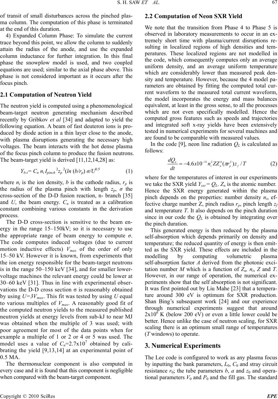 S. H. SAW ET AL. Copyright © 2010 SciRes EPE 67 of transit of small disturbances across the pinched plas- ma column. The computation of this phase is terminated at the end of this duration. 4) Expanded Column Phase: To simulate the current trace beyond this point, we allow the column to suddenly attain the radius of the anode, and use the expanded column inductance for further integration. In this final phase the snowplow model is used, and two coupled equations are used; similar to the axial phase above. This phase is not considered important as it occurs after the focus pinch. 2.1 Computation of Neutron Yield The neutron yield is computed using a phenomenological beam-target neutron generating mechanism described recently by Gribkov et al [34] and adapted to yield the following equation. A beam of fast deuteron ions is pro- duced by diode action in a thin layer close to the anode, with plasma disruptions generating the necessary high voltages. The beam interacts with the hot dense plasma of the focus pinch column to produce the fusion neutrons. The beam-target yield is derived [11,12,14,28] as: Yb-t= Cn ni Ipinch 2zp 2(ln (b/rp) σ/U0.5 (1) where ni is the ion density, b is the cathode radius, rp is the radius of the plasma pinch with length zp, σ the cross-section of the D-D fusion reaction, n- branch [35] and U, the beam energy. Cn is treated as a calibration constant combining various constants in the derivation process. The D-D cross-section is sensitive to the beam en- ergy in the range 15–150kV; so it is necessary to use the appropriate range of beam energy to compute σ. The code computes induced voltages (due to current motion inductive effects) Vmax of the order of only 15–50 kV. However it is known, from experiments that the ion energy responsible for the beam-target neutrons is in the range 50–150 keV [34], and for smaller lower- voltage machines the relevant energy could be lower at 30–60 keV [31]. Thus in line with experimental obser- vations the D-D cross section σ is reasonably obtained by using U=3Vmax. This fit was tested by using U equal to various multiples of Vmax. A reasonably good fit of the computed neutron yields to the measured published neutron yields at energy levels from sub-kJ to near MJ was obtained when the multiple of 3 was used; with poor agreement for most of the data points when for example a multiple of 1 or 2 or 4 or 5 was used. The model uses a value of Cn=2.7x10⁷ obtained by cali- brating the yield [9,13,14] at an experimental point of 0.5 MA. The thermonuclear component is also computed in every case and it is found that this component is negligible when compared with the beam-target component. 2.2 Computation of Neon SXR Yield We note that the transition from Phase 4 to Phase 5 is observed in laboratory measurements to occur in an ex- tremely short time with plasma/current disruptions re- sulting in localized regions of high densities and tem- peratures. These localized regions are not modelled in the code, which consequently computes only an average uniform density, and an average uniform temperature which are considerably lower than measured peak den- sity and temperature. However, because the 4 model pa- rameters are obtained by fitting the computed total cur- rent waveform to the measured total current waveform, the model incorporates the energy and mass balances equivalent, at least in the gross sense, to all the processes which are not even specifically modelled. Hence the computed gross features such as speeds and trajectories and integrated soft x-ray yields have been extensively tested in numerical experiments for several machines and are found to be comparable with measured values. In the code [9], neon line radiation QL is calculated as follows: TzrZZnx d t dQ fpni L/)(106.4 24231 (2) where for the temperatures of interest in our experiments we take the SXR yield Ysxr = QL. Zn is the atomic number. Hence the SXR energy generated within the plasma pinch depends on the properties: number density ni, ef- fective charge number Z, pinch radius rp, pinch length zf and temperature T. It also depends on the pinch duration since in our code the QL is obtained by integrating over the pinch duration. This generated energy is then reduced by the plasma self-absorption which depends primarily on density and temperature; the reduced quantity of energy is then emit- ted as the SXR yield. These effects are included in the modelling by computing volumetric plasma self-absorption factor A derived from the photonic exci- tation number M which is a function of Zn, ni, Z and T. However, in our range of operation, the numerical ex- periments show that the self absorption is not significant. It was first pointed out by Liu Mahe [23] that a tempera- ture around 300 eV is optimum for SXR production. Shan Bing’s subsequent work [24] and our experience through numerical experiments suggest that around 2x10⁶ K (below 200 eV) or even a little lower could be better. Hence unlike the case of neutron scaling, for SXR scaling there is an optimum small range of temperatures (T windows) to operate. 3. Numerical Experiments The Lee code is configured to work as any plasma focus by inputting the bank parameters, L0, C0 and stray circuit resistance r0; the tube parameters b, a and z0 and opera- tional parameters V0 and P0 and the fill gas. The standard 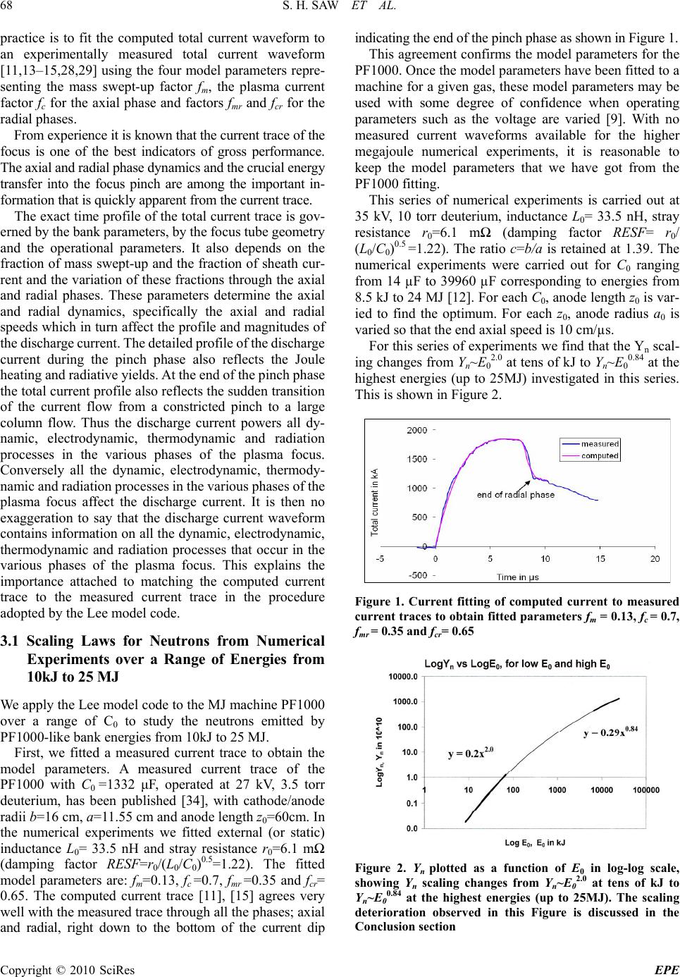 S. H. SAW ET AL. Copyright © 2010 SciRes EPE 68 practice is to fit the computed total current waveform to an experimentally measured total current waveform [11,13–15,28,29] using the four model parameters repre- senting the mass swept-up factor fm, the plasma current factor fc for the axial phase and factors fmr and fcr for the radial phases. From experience it is known that the current trace of the focus is one of the best indicators of gross performance. The axial and radial phase dynamics and the crucial energy transfer into the focus pinch are among the important in- formation that is quickly apparent from the current trace. The exact time profile of the total current trace is gov- erned by the bank parameters, by the focus tube geometry and the operational parameters. It also depends on the fraction of mass swept-up and the fraction of sheath cur- rent and the variation of these fractions through the axial and radial phases. These parameters determine the axial and radial dynamics, specifically the axial and radial speeds which in turn affect the profile and magnitudes of the discharge current. The detailed profile of the discharge current during the pinch phase also reflects the Joule heating and radiative yields. At the end of the pinch phase the total current profile also reflects the sudden transition of the current flow from a constricted pinch to a large column flow. Thus the discharge current powers all dy- namic, electrodynamic, thermodynamic and radiation processes in the various phases of the plasma focus. Conversely all the dynamic, electrodynamic, thermody- namic and radiation processes in the various phases of the plasma focus affect the discharge current. It is then no exaggeration to say that the discharge current waveform contains information on all the dynamic, electrodynamic, thermodynamic and radiation processes that occur in the various phases of the plasma focus. This explains the importance attached to matching the computed current trace to the measured current trace in the procedure adopted by the Lee model code. 3.1 Scaling Laws for Neutrons from Numerical Experiments over a Range of Energies from 10kJ to 25 MJ We apply the Lee model code to the MJ machine PF1000 over a range of C0 to study the neutrons emitted by PF1000-like bank energies from 10kJ to 25 MJ. First, we fitted a measured current trace to obtain the model parameters. A measured current trace of the PF1000 with C0 =1332 μF, operated at 27 kV, 3.5 torr deuterium, has been published [34], with cathode/anode radii b=16 cm, a=11.55 cm and anode length z0=60cm. In the numerical experiments we fitted external (or static) inductance L0= 33.5 nH and stray resistance r0=6.1 mΩ (damping factor RESF=r0/(L0/C0)0.5=1.22). The fitted model parameters are: fm=0.13, fc =0.7, fmr =0.35 and fcr= 0.65. The computed current trace [11], [15] agrees very well with the measured trace through all the phases; axial and radial, right down to the bottom of the current dip indicating the end of the pinch phase as shown in Figure 1. This agreement confirms the model parameters for the PF1000. Once the model parameters have been fitted to a machine for a given gas, these model parameters may be used with some degree of confidence when operating parameters such as the voltage are varied [9]. With no measured current waveforms available for the higher megajoule numerical experiments, it is reasonable to keep the model parameters that we have got from the PF1000 fitting. This series of numerical experiments is carried out at 35 kV, 10 torr deuterium, inductance L0= 33.5 nH, stray resistance r0=6.1 mΩ (damping factor RESF= r0/ (L0/C0)0.5 =1.22). The ratio c=b/a is retained at 1.39. The numerical experiments were carried out for C0 ranging from 14 µF to 39960 µF corresponding to energies from 8.5 kJ to 24 MJ [12]. For each C0, anode length z0 is var- ied to find the optimum. For each z0, anode radius a0 is varied so that the end axial speed is 10 cm/µs. For this series of experiments we find that the Yn scal- ing changes from Yn~E0 2.0 at tens of kJ to Yn~E0 0.84 at the highest energies (up to 25MJ) investigated in this series. This is shown in Figure 2. Figure 1. Current fitting of computed current to measured current traces to obtain fitted parameters fm = 0.13, fc = 0.7, fmr = 0.35 and fcr= 0.65 Figure 2. Yn plotted as a function of E0 in log-log scale, showing Yn scaling changes from Yn~E02.0 at tens of kJ to Yn~E00.84 at the highest energies (up to 25MJ). The scaling deterioration observed in this Figure is discussed in the Conclusion section 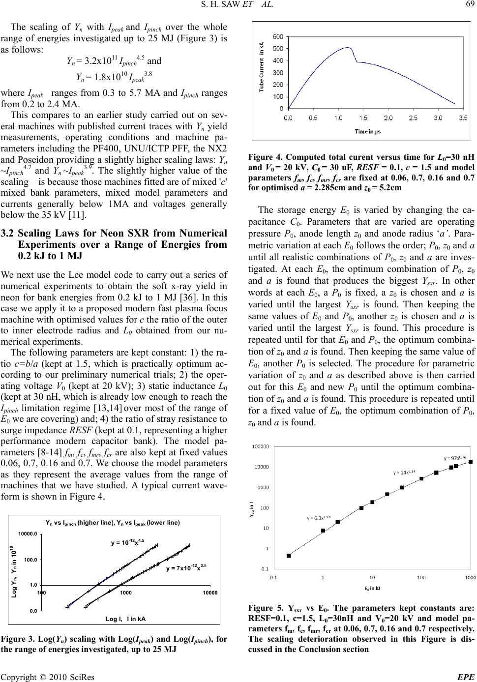 S. H. SAW ET AL. Copyright © 2010 SciRes EPE 69 The scaling of Yn with Ipeak and Ipinch over the whole range of energies investigated up to 25 MJ (Figure 3) is as follows: Yn = 3.2x10¹¹ Ipinch 4.5 and Yn = 1.8x10¹⁰ Ipeak 3.8 where Ipeak ranges from 0.3 to 5.7 MA and Ipinch ranges from 0.2 to 2.4 MA. This compares to an earlier study carried out on sev- eral machines with published current traces with Yn yield measurements, operating conditions and machine pa- rameters including the PF400, UNU/ICTP PFF, the NX2 and Poseidon providing a slightly higher scaling laws: Yn ~Ipinch 4.7 and Yn ~Ipeak 3.9. The slightly higher value of the scaling is because those machines fitted are of mixed 'c' mixed bank parameters, mixed model parameters and currents generally below 1MA and voltages generally below the 35 kV [11]. 3.2 Scaling Laws for Neon SXR from Numerical Experiments over a Range of Energies from 0.2 kJ to 1 MJ We next use the Lee model code to carry out a series of numerical experiments to obtain the soft x-ray yield in neon for bank energies from 0.2 kJ to 1 MJ [36]. In this case we apply it to a proposed modern fast plasma focus machine with optimised values for c the ratio of the outer to inner electrode radius and L0 obtained from our nu- merical experiments. The following parameters are kept constant: 1) the ra- tio c=b/a (kept at 1.5, which is practically optimum ac- cording to our preliminary numerical trials; 2) the oper- ating voltage V0 (kept at 20 kV); 3) static inductance L0 (kept at 30 nH, which is already low enough to reach the Ipinch limitation regime [13,14] over most of the range of E0 we are covering) and; 4) the ratio of stray resistance to surge impedance RESF (kept at 0.1, representing a higher performance modern capacitor bank). The model pa- rameters [8-14] fm, fc, fmr, fcr are also kept at fixed values 0.06, 0.7, 0.16 and 0.7. We choose the model parameters as they represent the average values from the range of machines that we have studied. A typical current wave- form is shown in Figure 4. Y n vs I pinch (higher line), Y n vs I peak (lower l i n e) y = 10 -12 x 4.5 y = 7x10 -12 x 3.8 0.0 1.0 100.0 10000.0 1001000 10000 Log I, I in kA Log Y n , Y n in 10 10 Figure 3. Log(Yn) scaling with Log(Ipeak) and Log(Ipinch), for the range of energies investigated, up to 25 MJ Figure 4. Computed total curent versus time for L0=30 nH and V0 = 20 kV, C0 = 30 uF, RESF = 0.1, c = 1.5 and model parameters fm, fc, fmr, fcr are fixed at 0.06, 0.7, 0.16 and 0.7 for optimised a = 2.285cm and z0 = 5.2cm The storage energy E0 is varied by changing the ca- pacitance C0. Parameters that are varied are operating pressure P0, anode length z0 and anode radius ‘a’. Para- metric variation at each E0 follows the order; P0, z0 and a until all realistic combinations of P0, z0 and a are inves- tigated. At each E0, the optimum combination of P0, z0 and a is found that produces the biggest Ysxr. In other words at each E0, a P0 is fixed, a z0 is chosen and a is varied until the largest Ysxr is found. Then keeping the same values of E0 and P0, another z0 is chosen and a is varied until the largest Ysxr is found. This procedure is repeated until for that E0 and P0, the optimum combina- tion of z0 and a is found. Then keeping the same value of E0, another P0 is selected. The procedure for parametric variation of z0 and a as described above is then carried out for this E0 and new P0 until the optimum combina- tion of z0 and a is found. This procedure is repeated until for a fixed value of E0, the optimum combination of P0, z0 and a is found. Figure 5. Ysxr vs E0. The parameters kept constants are: RESF=0.1, c=1.5, L0=30nH and V0=20 kV and model pa- rameters fm, fc, fmr, fcr at 0.06, 0.7, 0.16 and 0.7 respectively. The scaling deterioration observed in this Figure is dis- cussed in the Conclusion section 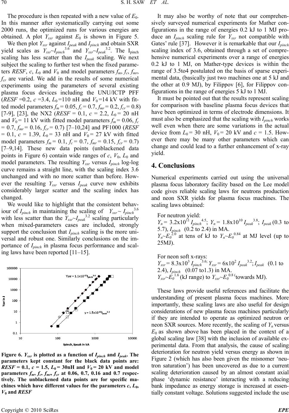 S. H. SAW ET AL. Copyright © 2010 SciRes EPE 70 The procedure is then repeated with a new value of E0. In this manner after systematically carrying out some 2000 runs, the optimized runs for various energies are obtained. A plot Ysxr against E0 is shown in Figure 5. We then plot Ysxr against Ipeak and Ipinch and obtain SXR yield scales as Ysxr~Ipinch 3.6 and Ysxr~Ipeak 3.2. The Ipinch scaling has less scatter than the Ipeak scaling. We next subject the scaling to further test when the fixed parame- ters RESF, c, L0 and V0 and model parameters fm, fc, fmr, fcr are varied. We add in the results of some numerical experiments using the parameters of several existing plasma focus devices including the UNU/ICTP PFF (RESF =0.2, c =3.4, L0 =110 nH and V0 =14 kV with fit- ted model parameters fm = 0.05, fc = 0.7, fmr = 0.2, fcr = 0.8) [7-9], [23], the NX2 (RESF = 0.1, c = 2.2, L0 = 20 nH and V0 = 11 kV with fitted model parameters fm = 0.06, fc = 0.7, fmr = 0.16, fcr = 0.7) [7–10,24] and PF1000 (RESF = 0.1, c = 1.39, L0 = 33 nH and V0 = 27 kV with fitted model parameters fm = 0.1, fc = 0.7, fmr = 0.15, fcr = 0.7) [7–9,14]. These new data points (unblackened data points in Figure 6) contain wide ranges of c, V0, L0 and model parameters. The resulting Ysxr versus Ipinch log-log curve remains a straight line, with the scaling index 3.6 unchanged and with no more scatter than before. How- ever the resulting Ysxr versus Ipeak curve now exhibits considerably larger scatter and the scaling index has changed. We would like to highlight that the consistent behav- iour of Ipinch in maintaining the scaling of Ysxr ~ Ipinch 3.6 with less scatter than the Ysxr~Ipeak 3.2 scaling particularly when mixed-parameters cases are included, strongly support the conclusion that Ipinch scaling is the more uni- versal and robust one. Similarly conclusions on the im- portance of Ipinch in plasma focus performance and scal- ing laws have been reported [11–15]. Figure 6. Ysxr is plotted as a function of Ipinch and Ipeak. The parameters kept constant for the black data points are: RESF = 0.1, c = 1.5, L0 = 30nH and V0 = 20 kV and model parameters fm, fc, fmr, fcr at 0.06, 0.7, 0.16 and 0.7 respec- tively. The unblackened data points are for specific ma- chines which have different values for the parameters c, L0, V0 and RESF It may also be worthy of note that our comprehen- sively surveyed numerical experiments for Mather con- figurations in the range of energies 0.2 kJ to 1 MJ pro- duce an Ipinch scaling rule for Y sxr not compatible with Gates’ rule [37]. However it is remarkable that our Ipinch scaling index of 3.6, obtained through a set of compre- hensive numerical experiments over a range of energies 0.2 kJ to 1 MJ, on Mather-type devices is within the range of 3.5to4 postulated on the basis of sparse experi- mental data, (basically just two machines one at 5 kJ and the other at 0.9 MJ), by Filippov [6], for Filippov con- figurations in the range of energies 5 kJ to 1 MJ. It must be pointed out that the results represent scaling for comparison with baseline plasma focus devices that have been optimized in terms of electrode dimensions. It must also be emphasized that the scaling with Ipinch works well even when there are some variations in the actual device from L0 = 30 nH, V0 = 20 kV and c = 1.5. How- ever there may be many other parameters which can change and could lead to a further enhancement of x-ray yield. 4. Conclusions Numerical experiments carried out using the universal plasma focus laboratory facility based on the Lee model code gives reliable scaling laws for neutrons production and neon SXR yields for plasma focus machines. The scaling laws obtained: For neutron yield: Yn = 3.2x10¹¹ Ipinch 4.5; Yn = 1.8x10¹⁰ Ipeak 3.8; Ipeak (0.3 to 5.7), Ipinch (0.2 to 2.4) in MA. Yn~E0 2.0 at tens of kJ to Y n~E0 0.84 at MJ level (up to 25MJ). For neon soft x-rays: Ysxr = 8.3x10³ Ipinch 3.6; Ysxr = 6x10² Ipeak 3.2; Ipeak (0.1 to 2.4), Ipinch (0.07 to1.3) in MA. Ysxr~E0 1.6 (kJ range) to Ysxr~E0 0.8 (towards MJ). These laws provide useful references and facilitate the understanding of present plasma focus machines. More importantly, these scaling laws are also useful for design considerations of new plasma focus machines particularly if they are intended to operate as optimized neutron or neon SXR sources. More recently, the scaling of Yn versus E0 as shown above has been placed in the context of a global scaling law [38] with the inclusion of available ex- perimental data. From that analysis, the cause of scaling deterioration for neutron yield versus energy as shown in Figure 2 (which has also been given the misnomer ‘neu- tron saturation’) has been uncovered as due to a current scaling deterioration caused by an almost constant axial phase ‘dynamic resistance’ interacting with a reducing bank impedance as energy storage is increased at essen- tially constant voltage. Solutions suggested include the use 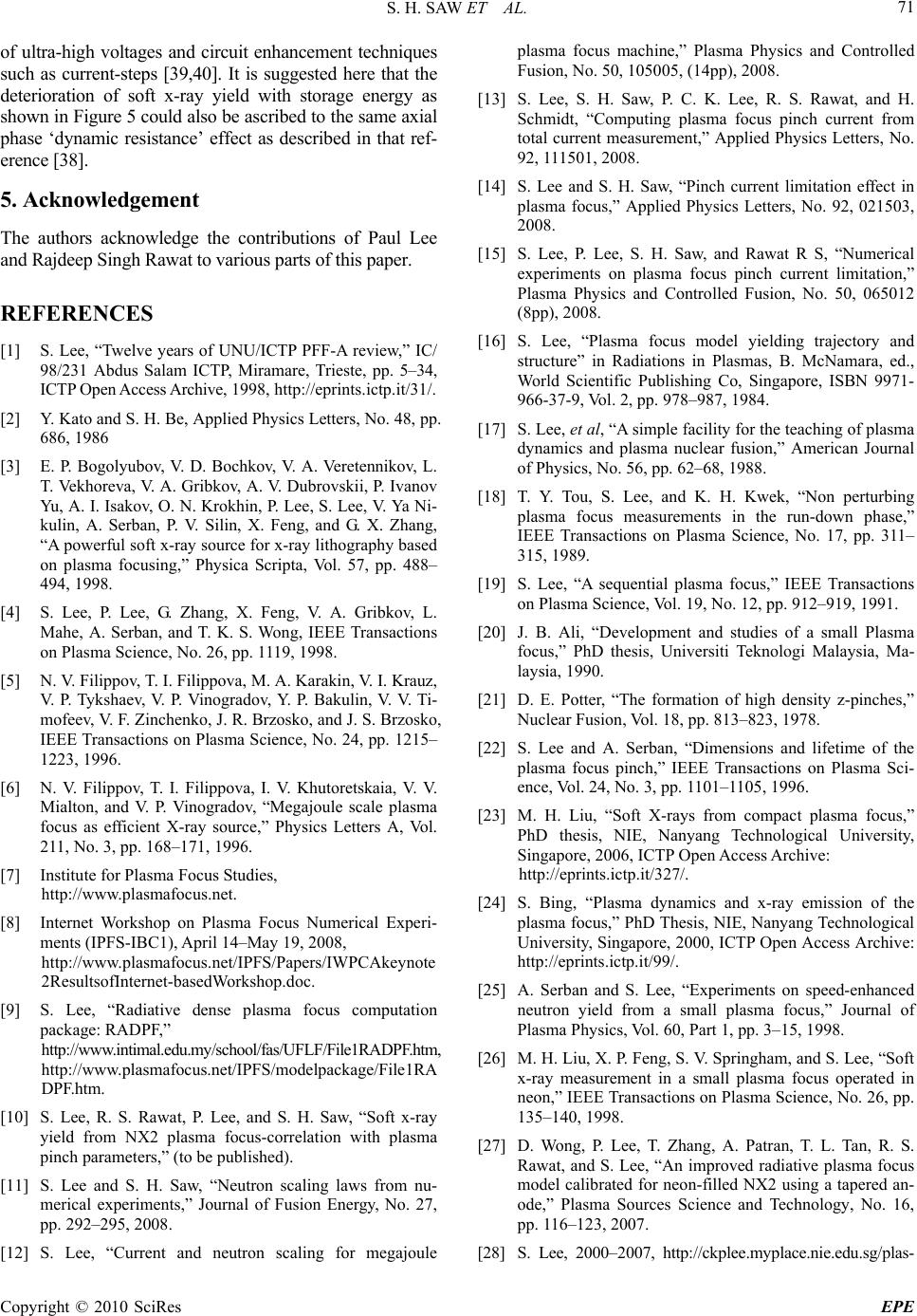 S. H. SAW ET AL. Copyright © 2010 SciRes EPE 71 of ultra-high voltages and circuit enhancement techniques such as current-steps [39,40]. It is suggested here that the deterioration of soft x-ray yield with storage energy as shown in Figure 5 could also be ascribed to the same axial phase ‘dynamic resistance’ effect as described in that ref- erence [38]. 5. Acknowledgement The authors acknowledge the contributions of Paul Lee and Rajdeep Singh Rawat to various parts of this paper. REFERENCES [1] S. Lee, “Twelve years of UNU/ICTP PFF-A review,” IC/ 98/231 Abdus Salam ICTP, Miramare, Trieste, pp. 5–34, ICTP Open Access Archive, 1998, http://eprints.ictp.it/31/. [2] Y. Kato and S. H. Be, Applied Physics Letters, No. 48, pp. 686, 1986 [3] E. P. Bogolyubov, V. D. Bochkov, V. A. Veretennikov, L. T. Vekhoreva, V. A. Gribkov, A. V. Dubrovskii, P. Ivanov Yu, A. I. Isakov, O. N. Krokhin, P. Lee, S. Lee, V. Ya Ni- kulin, A. Serban, P. V. Silin, X. Feng, and G. X. Zhang, “A powerful soft x-ray source for x-ray lithography based on plasma focusing,” Physica Scripta, Vol. 57, pp. 488– 494, 1998. [4] S. Lee, P. Lee, G. Zhang, X. Feng, V. A. Gribkov, L. Mahe, A. Serban, and T. K. S. Wong, IEEE Transactions on Plasma Science, No. 26, pp. 1119, 1998. [5] N. V. Filippov, T. I. Filippova, M. A. Karakin, V. I. Krauz, V. P. Tykshaev, V. P. Vinogradov, Y. P. Bakulin, V. V. Ti- mofeev, V. F. Zinchenko, J. R. Brzosko, and J. S. Brzosko, IEEE Transactions on Plasma Science, No. 24, pp. 1215– 1223, 1996. [6] N. V. Filippov, T. I. Filippova, I. V. Khutoretskaia, V. V. Mialton, and V. P. Vinogradov, “Megajoule scale plasma focus as efficient X-ray source,” Physics Letters A, Vol. 211, No. 3, pp. 168–171, 1996. [7] Institute for Plasma Focus Studies, http://www.plasmafocus.net. [8] Internet Workshop on Plasma Focus Numerical Experi- ments (IPFS-IBC1), April 14–May 19, 2008, http://www.plasmafocus.net/IPFS/Papers/IWPCAkeynote 2ResultsofInternet-basedWorkshop.doc. [9] S. Lee, “Radiative dense plasma focus computation package: RADPF,” http://www.intimal.edu.my/school/fas/UFLF/File1RADPF.htm, http://www.plasmafocus.net/IPFS/modelpackage/File1RA DPF.htm. [10] S. Lee, R. S. Rawat, P. Lee, and S. H. Saw, “Soft x-ray yield from NX2 plasma focus-correlation with plasma pinch parameters,” (to be published). [11] S. Lee and S. H. Saw, “Neutron scaling laws from nu- merical experiments,” Journal of Fusion Energy, No. 27, pp. 292–295, 2008. [12] S. Lee, “Current and neutron scaling for megajoule plasma focus machine,” Plasma Physics and Controlled Fusion, No. 50, 105005, (14pp), 2008. [13] S. Lee, S. H. Saw, P. C. K. Lee, R. S. Rawat, and H. Schmidt, “Computing plasma focus pinch current from total current measurement,” Applied Physics Letters, No. 92, 111501, 2008. [14] S. Lee and S. H. Saw, “Pinch current limitation effect in plasma focus,” Applied Physics Letters, No. 92, 021503, 2008. [15] S. Lee, P. Lee, S. H. Saw, and Rawat R S, “Numerical experiments on plasma focus pinch current limitation,” Plasma Physics and Controlled Fusion, No. 50, 065012 (8pp), 2008. [16] S. Lee, “Plasma focus model yielding trajectory and structure” in Radiations in Plasmas, B. McNamara, ed., World Scientific Publishing Co, Singapore, ISBN 9971- 966-37-9, Vol. 2, pp. 978–987, 1984. [17] S. Lee, et al, “A simple facility for the teaching of plasma dynamics and plasma nuclear fusion,” American Journal of Physics, No. 56, pp. 62–68, 1988. [18] T. Y. Tou, S. Lee, and K. H. Kwek, “Non perturbing plasma focus measurements in the run-down phase,” IEEE Transactions on Plasma Science, No. 17, pp. 311– 315, 1989. [19] S. Lee, “A sequential plasma focus,” IEEE Transactions on Plasma Science, Vol. 19, No. 12, pp. 912–919, 1991. [20] J. B. Ali, “Development and studies of a small Plasma focus,” PhD thesis, Universiti Teknologi Malaysia, Ma- laysia, 1990. [21] D. E. Potter, “The formation of high density z-pinches,” Nuclear Fusion, Vol. 18, pp. 813–823, 1978. [22] S. Lee and A. Serban, “Dimensions and lifetime of the plasma focus pinch,” IEEE Transactions on Plasma Sci- ence, Vol. 24, No. 3, pp. 1101–1105, 1996. [23] M. H. Liu, “Soft X-rays from compact plasma focus,” PhD thesis, NIE, Nanyang Technological University, Singapore, 2006, ICTP Open Access Archive: http://eprints.ictp.it/327/. [24] S. Bing, “Plasma dynamics and x-ray emission of the plasma focus,” PhD Thesis, NIE, Nanyang Technological University, Singapore, 2000, ICTP Open Access Archive: http://eprints.ictp.it/99/. [25] A. Serban and S. Lee, “Experiments on speed-enhanced neutron yield from a small plasma focus,” Journal of Plasma Physics, Vol. 60, Part 1, pp. 3–15, 1998. [26] M. H. Liu, X. P. Feng, S. V. Springham, and S. Lee, “Soft x-ray measurement in a small plasma focus operated in neon,” IEEE Transactions on Plasma Science, No. 26, pp. 135–140, 1998. [27] D. Wong, P. Lee, T. Zhang, A. Patran, T. L. Tan, R. S. Rawat, and S. Lee, “An improved radiative plasma focus model calibrated for neon-filled NX2 using a tapered an- ode,” Plasma Sources Science and Technology, No. 16, pp. 116–123, 2007. [28] S. Lee, 2000–2007, http://ckplee.myplace.nie.edu.sg/plas-  S. H. SAW ET AL. Copyright © 2010 SciRes EPE 72 maphysics/. [29] S. Lee, 2005, ICTP Open Access Archive: http://eprints. ictp.it/85/. [30] M. A. Mohammadi, S. Sobhanian, C. S. Wong, S. Lee, P. Lee, and R. S. Rawat, “The effect of anode shape on neon soft x-ray emissions and current sheath configuration in plasma focus device,” Journal of Physics D: Applied Physics, 42, 2009, 045203 (10pp). [31] Springham S V, Lee S and Rafique M S, “Correlated deuteron energy spectra and neutron yield for a 3 kJ plasma focus,” Plasma Physics Controlled Fusion, Vol. 42, pp. 1023–1032, 2000. [32] S. Lee, P. Lee, G. Zhang, X. Feng, V. A. Gribkov, M. Liu, A. Serban, and T. Wong “High rep rate high performance plasma focus as a powerful radiation source,” IEEE Transactions on Plasma Science, Vol. 26, No. 4, pp. 1119– 1126, 1998. [33] V. Siahpoush, M. A. Tafreshi, S. Sobhanian, and S. Khor- ram, “Adaptation of Sing Lee’s model to the Filippov type plasma focus geometry,” Plasma Physics Controlled Fusion, No. 47, pp. 1065–1072, 2005. [34] V. A. Gribkov, A. Banaszak, B. Bienkowska, A. V. Du- brovsky, I. Ivanova-Stanik, L. Jakubowski, L. Karpinski, R. A. Miklaszewski, M. Paduch, M. J. Sadowski, M. Scholz, A. Szydlowski, and K. Tomaszewski, “Plasma dynamics in the PF-1000 device under full-scale energy storage: II, Fast electron and ion characteristics versus neutron emission parameters and gun optimization per- spectives,” Journal of Physics D: Applied Physics, No. 40, pp. 3592–3607, 2007. [35] J. D. Huba, Plasma Formulary page, No. 44, 2006. [36] S. Lee, S. H. Saw, P. Lee, and R. S. Rawat, “Numerical experiments on plasma focus neon soft x-ray scaling,” Plasma Physics and Controlled Fusion, No. 51, 105013 (8pp), 2009, Available at http://stacks.iop.org/PPCF/51/105013. [37] D. C. Gates, Proceedings of the 2nd International Con- ference on Energy Storage, Compression and Switching, Venice, No. 2, pp. 3239, Plenum Press, New York, 1983. [38] S. Lee, “Neutron yield saturation in plasma focus-A fundamental cause,” Applied Physics Letters, No. 95, 151503, First online 15 October 2009. [39] S. H. Saw, “Experimental studies of a current-stepped pinch,” PhD Thesis Universiti Malaya, Malaysia, 1991. [40] S. Lee, “A current-stepping technique to enhance pinch compression,” Journal of Physics D: Applied Physics, No. 17, pp. 733–739, 1984. |

