Paper Menu >>
Journal Menu >>
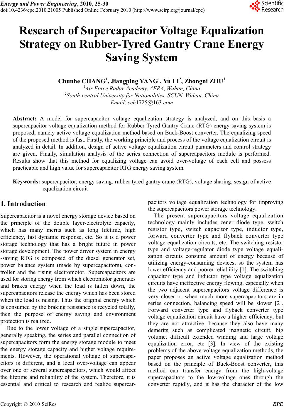 Energy and Power Engineering, 2010, 25-30 doi:10.4236/epe.2010.21005 Published Online February 2010 (http://www.scirp.org/journal/epe) Copyright © 2010 SciRes EPE Research of Supercapacitor Voltage Equalization Strategy on Rubber-Tyred Gantry Crane Energy Saving System Chunhe CHANG1, Jiangping YANG1, Yu LI2, Zho ngni ZHU1 1Air Force Radar Academy, AFRA, Wuhan, China 2South-central University for Nationalities, SCUN, Wuhan, China Email: cch1725@163.com Abstract: A model for supercapacitor voltage equalization strategy is analyzed, and on this basis a supercapacitor voltage equalization method for Rubber Tyred Gantry Crane (RTG) energy saving system is proposed, namely active voltage equalization method based on Buck-Boost converter. The equalizing speed of the proposed method is fast. Firstly, the working principle and process of the voltage equalization circuit is analyzed in detail. In addition, design of active voltage equalization circuit parameters and control strategy are given. Finally, simulation analysis of the series connection of supercapacitors module is performed. Results show that this method for equalizing voltage can avoid over-voltage of each cell and possess practicable and high value for supercapacitor RTG energy saving system. Keywords: supercapacitor, energy saving, rubber tyred gantry crane (RTG), voltage sharing, sesign of active equalization circuit 1. Introduction Supercapacitor is a novel energy storage device based on the principle of the double layer-electrolyte capacity, which has many merits such as long lifetime, high efficiency, fast dynamic response, etc. So it is a power storage technology that has a bright future in power storage development. The power driver system in energy -saving RTG is composed of the diesel generator set, power balance system (made by supercapacitors), con- troller and the rising electromotor. Supercapacitors are used for storing energy from which electromotor gene r a te s and brakes energy when the load is fallen down, the superc apacitors rele ase the energy wh ich has been stored when the load is raising. Thus the original energy which is consumed by the braking resistance is recycled totally, then the purpose of energy saving and environment protection is realized. Due to the lower voltage of a single supercapacitor, generally speaking, the series and parallel connection of supercapacitors form the energy storage module to meet the energy storage capacity and higher voltage require- ments. However, the operational voltage of supercapa- citors is different, and a local over-voltage can appear over one or several supercapacitors, which would affect the lifetime and reliability of the system. Therefore, it is essential and critical to research and realize supercar- pacitors voltage equalization technology for improving the supercapacitors power storage technology. The present supercapacitors voltage equalization technology mainly includes zener diode type, switch resistor type, switch capacitor type, inductor type, forward converter type and flyback converter type voltage equalization circuits, etc. The switching resistor type and voltage-regulator diode type voltage equali- zation circuits consume amount of energy because of utilizing energy-consuming devices, so the system has lower efficiency and poorer reliability [1]. Th e switching capacitor type and inductor type voltage equalization circuits have ineffective energy flowing, especially when the two adjacent supercapacitors voltage difference is very closer or when much more supercapacitors are in series connection, balancing speed will be slower [2]. Forward converter type and flyback converter type voltage equalization circuit have a higher efficiency, but they are not attractive, because they also have many demerits such as complicated magnetic circuit, big volume, difficult extended winding and large voltage equalization error, etc [3]. In view of the existing problems of the above voltage equalization methods, the paper proposes an active voltage equalization method based on the principle of Buck-Boost converter, this method can transfer energy from the high-voltage supercapacitors to the low-voltage ones through the converter rapidly, and it has the character of the low 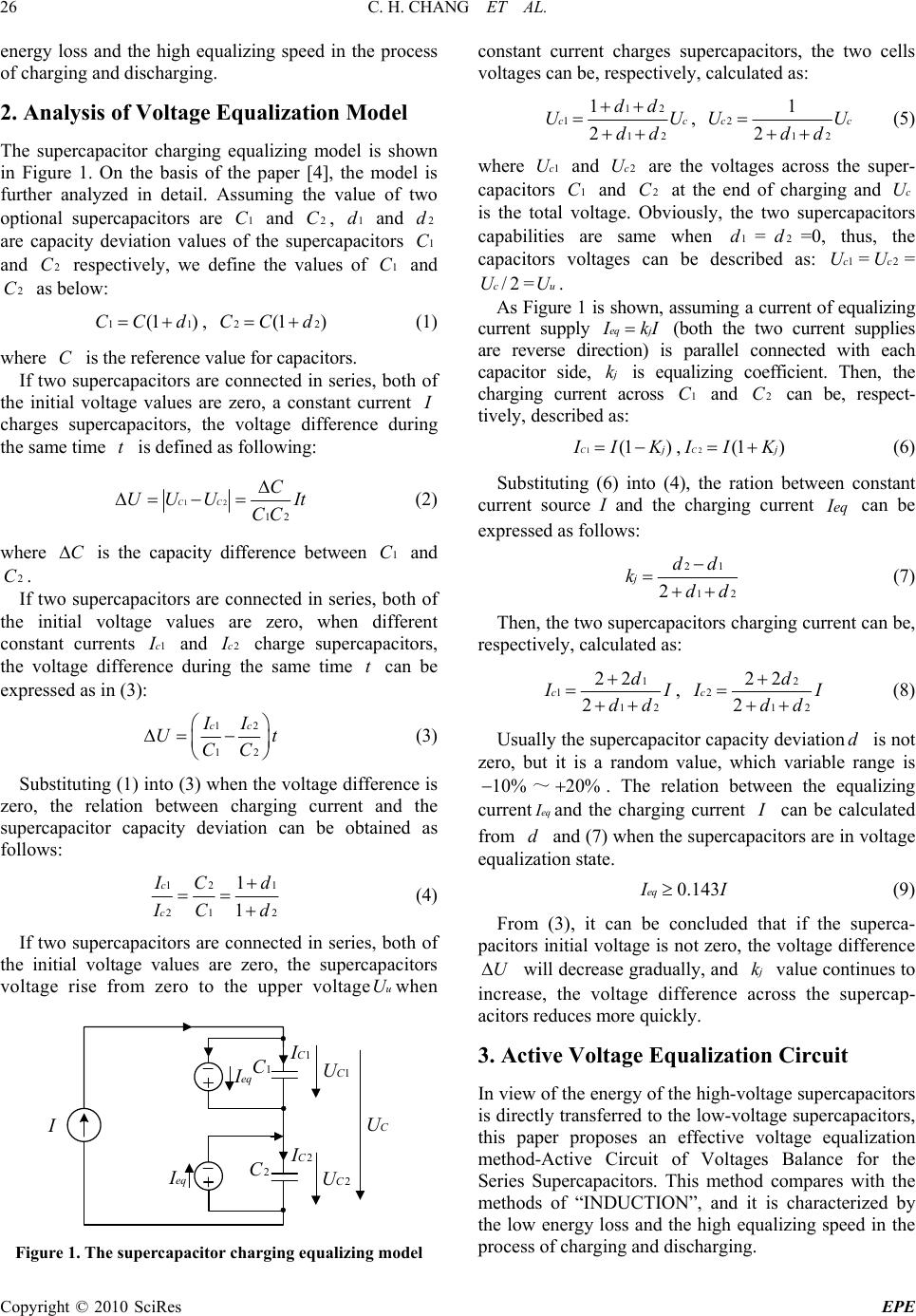 C. H. CHANG ET AL. Copyright © 2010 SciRes EPE 26 energy loss and the high equalizing speed in the process of charging and discharging. 2. Analysis of Voltage E q ua l ization Model The supercapacitor charging equalizing model is shown in Figure 1. On the basis of the paper [4], the model is further analyzed in detail. Assuming the value of two optional supercapacitors are 1C and 2C, 1d and 2d are capacity deviation values of the supercapacitors 1C and 2C respectively, we define the values of 1C and 2C as below: 11(1 )CC d, 22(1 )CC d (1) where C is the reference value for capacitors. If two supercapacitors are connected in series, both of the initial voltage values are zero, a constant current I charges supercapacitors, the voltage difference during the same time t is defined as following: 12 12 CC C UUU It CC (2) where C is the capacity difference between 1C and 2C. If two supercapacitors are connected in series, both of the initial voltage values are zero, when different constant currents 1c I and 2c I charge supercapacitors, the voltage difference during the same time t can be expressed as in (3): 12 12 ccII Ut CC (3) Substituting (1) into (3) when the voltage d ifference is zero, the relation between charging current and the supercapacitor capacity deviation can be obtained as follows: 12 1 21 2 1 1 c c I Cd I Cd (4) If two supercapacitors are connected in series, both of the initial voltage values are zero, the supercapacitors voltage rise from zero to the upper voltageuUwhen eq I eq I 1CI 2C I 1C U 2C U C U I 1 C 2 C Figure 1. The supercapacitor charging equalizing mode l constant current charges supercapacitors, the two cells voltages can be, respectively, calculated as: 12 1 12 1 2 cc dd UU dd , 2 12 1 2 ccUU dd (5) where 1cU and 2cU are the voltages across the super- capacitors 1C and 2C at the end of charging and cU is the total voltage. Obviously, the two supercapacitors capabilities are same when 1d=2d=0, thus, the capacitors voltages can be described as: 1cU=2cU= /2cU=uU. As Figure 1 is shown, assuming a current of equalizing current supply eq j I kI (both the two current supplies are reverse direction) is parallel connected with each capacitor side, j k is equalizing coefficient. Then, the charging current across 1C and 2C can be, respect- tively, described as: 1(1 )C j I IK ,2(1 )C j I IK (6) Substituting (6) into (4), the ration between constant current source I and the charging current eqI can be expressed as follows: 21 12 2 jdd kdd (7) Then, the two supercapacitors charging current can be, respectively, calculated as: 1 1 12 22 2 cd I I dd , 2 2 12 22 2 cd I I dd (8) Usually the supercapacitor capacity deviationd is not zero, but it is a random value, which variable range is 10% ~20% . The relation between the equalizing current eqIand the charging current I can be calculated from d and (7) when the supercapacitors are in voltage equalization state. 0.143eq I I (9) From (3), it can be concluded that if the superca- pacitors initial voltage is not zero, the voltage difference U will decrease gradually, and j k value continues to increase, the voltage difference across the supercap- acitors reduces more quickly. 3. Active Voltage Equalization Circuit In view of the energy of the high-voltage supercapacitors is directly transferred to the low-voltage supercapacitors, this paper proposes an effective voltage equalization method-Active Circuit of Voltages Balance for the Series Supercapacitors. This method compares with the methods of “INDUCTION”, and it is characterized by the low energy loss and the high equalizing speed in the process of charging and discharging. 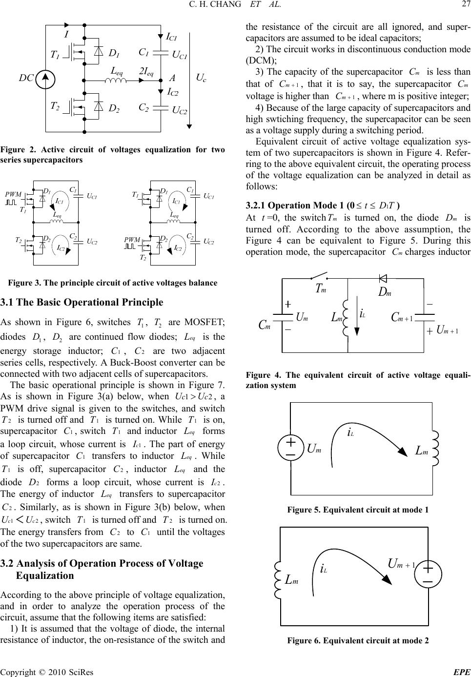 C. H. CHANG ET AL. Copyright © 2010 SciRes EPE 27 Figure 2. Active circuit of voltages equalization for two series supercapacitors Figure 3. The principle circuit of active voltages balance 3.1 The Basic Operational Principle As shown in Figure 6, switches 1 T, 2 T are MOSFET; diodes 1 D, 2 D are continued flow diodes; eqL is the energy storage inductor; 1C, 2C are two adjacent series cells, respectively. A Buck-Boost converter can be connected with two adjacent cells of supercapacitors. The basic operational principle is shown in Figure 7. As is shown in Figure 3(a) below, when 12ccUU, a PWM drive signal is given to the switches, and switch 2T is turned off and 1T is turned on. While 1T is on, supercapacitor 1C, switch 1T and inductor eqL forms a loop circuit, whose current is 1c I . The part of energy of supercapacitor 1C transfers to inductor eqL. While 1T is off, supercapacitor 2C, inductor eqL and the diode 2D forms a loop circuit, whose current is 2c I . The energy of inductor eqL transfers to supercapacitor 2C. Similarly, as is shown in Figure 3(b) below, when 1cU<2cU, switch 1T is turned off and 2T is turned on. The energy transfers from 2C to 1C until the voltages of the two supercapacitors are same. 3.2 Analysis of Operation Process of Voltage Equalization According to the above principle of voltage equalization, and in order to analyze the operation process of the circuit, assume that the following items are satisfied: 1) It is assumed that the voltage of diode, the internal resistance of inductor, the on-resistance of the switch and the resistance of the circuit are all ignored, and super- capacitors are assumed to be ideal capacitors; 2) The circuit works in discontinuous conduction mode (DCM); 3) The capacity of the supercapacitor mC is less than that of 1mC , that it is to say, the supercapacitor mC voltage is higher than 1mC , where m is positive integer; 4) Because of the large capacity of supercapacitors and high swtiching frequency, the supercapacitor can be seen as a voltage supply during a switching period. Equivalent circuit of active voltage equalization sys- tem of two supercapacitors is shown in Figure 4. Refer- ring to the above equivalent circuit, the operating process of the voltage equalization can be analyzed in detail as follows: 3.2.1 Operation Mode 1 (0t1DT) At t=0, the switchmT is turned on, the diode mD is turned off. According to the above assumption, the Figure 4 can be equivalent to Figure 5. During this operation mode, the supercapacitor mCcharges inductor m U m C m L 1m U 1m C mT m D L i Figure 4. The equivalent circuit of active voltage equali- zation system m U L i m L Figure 5. Equivalent circuit at mode 1 1m U L i m L Figure 6. Equivalent circuit at mode 2 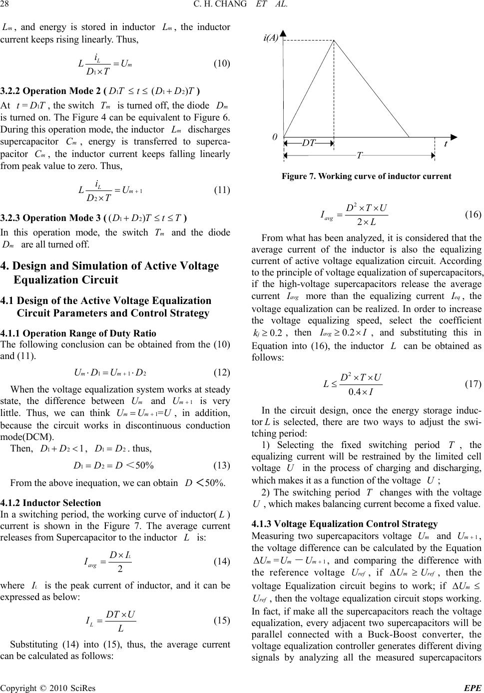 C. H. CHANG ET AL. Copyright © 2010 SciRes EPE 28 mL, and energy is stored in inductor mL, the inductor current keeps rising linearly. Thus, 1 Lm i LU DT (10) 3.2.2 Operation Mode 2 (1DT t12()DDT) At t=1DT, the switch mT is turned off, the diode mD is turned on. The Figure 4 can be equivalent to Figure 6. During this opera tion mode, th e inductor mL discharges supercapacitor mC, energy is transferred to superca- pacitor mC, the inductor current keeps falling linearly from peak value to zero. Thus, 1 2 Lm i LU DT (11) 3.2.3 Operation Mode 3 (12()DDTtT ) In this operation mode, the switch mT and the diode mD are all turned off. 4. Design and Simulation of Active Voltage Equalization Circuit 4.1 Design of the Active Voltage Equalization Circuit Parameters and Control Strategy 4.1.1 Operation Range of Duty Ratio The following conclusion can be obtained from the (10) and (11). 112mmUD UD (12) When the voltage equalization system works at steady state, the difference between mU and 1mU is very little. Thus, we can think 1=mmUU U, in addition, because the circuit works in discontinuous conduction mode(DCM). Then, 121DD, 12DD. thus, 12DDD<50% (13) From the above inequation, we can obtain D<50%. 4.1.2 Inductor Selection In a switching period, the working curve of inductor(L) current is shown in the Figure 7. The average current releases from Supercapacitor to the inductor L is: 2 L avg DI I (14) where L I is the peak current of inductor, and it can be expressed as below: L DT U IL (15) Substituting (14) into (15), thus, the average current can be calculated as follows: Figure 7. Working curve of inductor current 2 2 avg DTU IL (16) From what has been analyzed, it is considered that the average current of the inductor is also the equalizing current of active voltage equalization circuit. According to the principle of voltage equalization of supercapacitors, if the high-voltage supercapacitors release the average current avg I more than the equalizing current eq I , the voltage equalization can be realized. In order to increase the voltage equalizing speed, select the coefficient 0.2jk, then 0.2avg I I, and substituting this in Equation into (16), the inductor L can be obtained as follows: 2 0.4 DTU L I (17) In the circuit design, once the energy storage induc- tor Lis selected, there are two ways to adjust the swi- tching period: 1) Selecting the fixed switching period T, the equalizing current will be restrained by the limited cell voltage U in the process of charging and discharging, which makes it as a function of the v oltage U; 2) The switching period T changes with the voltage U, which makes balancing current become a fixed value. 4.1.3 Volta ge E qual i zation Control Strat e gy Measuring two supercapacitors voltage mU and 1mU , the voltage difference can be calculated by the Equation mU =mU-1mU , and comparing the difference with the reference voltage refU, if mUrefU, then the voltage Equalization circuit begins to work; if mU refU, then the voltage equalization circuit stops working. In fact, if make all the supercapacitors reach the voltage equalization, every adjacent two supercapacitors will be parallel connected with a Buck-Boost converter, the voltage equalization controller generates different diving signals by analyzing all the measured supercapacitors  C. H. CHANG ET AL. Copyright © 2010 SciRes EPE 29 Figure 8. Active circuit of voltages balance for five superca-pacitors series Figure 9. Active circuit of voltages balance for ten supercapacitors Figure 10. Simulation results of voltages balance for super- capacitors voltage to drive MOSFET, in this way, equalization among all supercapacitors will be achieved at last. 4.2 The Extension Circuit of Voltage Equalization Extending the above circuit, we can make it suitable for more series supercapacitor cells to meet the requirement of the RTG energy saving system. As is shown in Figure 8, we can see every two adjacent supercapacitors constitute a group which is controlled to balance voltage by a Buck-Boost converter. For example, the converter, which is composed of 1T, 1D, 2T and 2D, balances the voltages between 1C and 2C, and another one is composed of 2T, 2D, 3'Tand 3'D, balances the volt- ages between 2C and 3C.Th e principle of equalization among 3C, 4C and 5C is the same as the above [5]. Consider ing the demand of hu ndreds of super capacitor cells in RTG energy saving system, the series structure, as shown in Figure 8, makes the control components increase markedly and the control circuit become complicated. So the series and parallel structure in Figure 9, can be adopted in practical application. 4.3 Saber Simulation Analysis In order to verify the character of the active voltage balance circuit in the energy recycling RTG system, we research the circuit composed of two supercapacitor cells in series module by the simulation study of Saber. Assume that the capacitance of one supercapacitor is  C. H. CHANG ET AL. Copyright © 2010 SciRes EPE 30 800F and the other one is 1000F, the constant charging current is 100A, the rate voltage of the supercapacitor is 2.7 V, the energy storage inductor is 1.36uH and the switching frequency is 10 kHz. Figure 10 describes the process of charging two super- capacitors. It can be seen, at the end of the process, that the voltages of two supercapacitors become the same, no over-voltage. The result of Saber simulation indicates that active voltage balance circuit amends the inconsis- tency of the supercapacitor voltage greatly. 5. Conclusions The active voltage equalization circuit based on the reversible Buck-Boost converter has been discussed in this paper. Theoretical analysis and simulation result show that the active control circuit can better solve the problem of the partial over-voltage over the super- capacitor groups. This method can be applied in the situation of higher charging or discharging current. Therefore, it has a high value to be used in the RTG energy saving system. REFERENCES [1] M. Okamura, “A basic study on power storage systems (translation of Japanese paper by the author with updating comments),”Journal Electrical Engineering in Japan, Vol.115, No.3, pp. 40–51, 1996. [2] J. Zhao, J. C. Jiang, and L. Y. Niu, “A novel charge equa- lization technique for electric vehicle battery system,” The Fifth International Conference on Power Electronics and Drive Systems, Singapore, 2003. [3] S. W. Moore and P. J. Schneider, “A review of cell equalization methods for lithiumion and lithium poly- mer battery systems,” SAE Technical Paper Series, pp. 1–5, 2001. [4] H. D. Li, Z. Y. Feng, and Z. P. Qi, “Study on a fast voltage balancing for supercapacitors,” Chinese Jour- nal of Power Sources, Vol. 37, No. 3, pp. 186–189, 2007. [5] A. Rufer and P. Barrade, “A supercapacitor-based energy-storage system for elevators with soft commutated interface,” IEEE Transactions on Industry Applications, Vol. 38, No. 5, pp. 1151–1159, 2002. |